Copyright [C] 1988 Volunteers in Technical Assistance All rights reserved. No part of this publication may be reproduced or transmitted in any form or by any means, electronic or mechanical, including photocopy, recording, or any information storage and retrieval system, without the written permission of the publisher.
(This is the third edition of a manual first published in 1963, with the support of the U. S. Agency for International Development, and revised in 1970, which has gone through eight major printings.)
Manufactured in the United States of America.
Set in Times Roman type on an IBM personal computer, a gift to VITA from International Business Machines Corporation, using WordPerfect software donated by WordPerfect Corporation.
Published by: Volunteers in Technical Assistance 1815 North Lynn Street, Suite 200 Arlington, Virginia 22209 USA 10 9 8 7 6 5 4 3 2 1
Library of Congress Cataloging-in-Publication Data
Bibliography: p. 413 1. Building--Amateurs' manuals. 2. Do-it-yourself work. 3. Home economics, Rural--Handbooks, manuals, etc. I. Volunteers in Technical Assistance. TH148.V64 1988 620'.41734 88-5700 ISBN 0-86619-275-1
Table of Contents
FOREWORD NOTES ON USING THE HANDBOOK ABOUT VITA SYMBOLS AND ABBREVIATIONS
WATER RESOURCES
- Developing Water Sources
- Getting Ground Water from Wells and Springs
- Ground Water Flow of Water to Wells
- Where To Dig a Well Well
- Casing and Seal Well Development
- Tubewells
- Well Casing and Platforms
- Hand-Operated Drilling Equipment
- Dry Bucket Well
- Drilling Driven Wells
- Dug Wells
- Sealed Dug Well
- Deep Dug Well
- Reconstructing Dug Wells Spring Development
- Water Lifting and Transport
- Overview Moving Water
- Lifting Water
- Water Transport
- Estimating Small Stream Water Flow
- Measuring Water Flow in Partially Filled Pipes
- Determining Probable Flow with Known Reservior Height and Size and Length of Pipe
- Estimating Water Flow from Horizontal Pipes
- Determining Pipe Size or Velocity of Water in Pipes
- Estimating Flow Resistance of Pipe Fittings Bamboo Piping
- Water Lifting Pump Specifications: Choosing or Evaluating a Pump Determining Pump Capacity and Horsepower Requirements
- Determining Lift Pump Capability
- Simple Pumps
- Chain Pump for Irrigation
- Inertia Hand Pump Handle Mechanism for Hand Pumps
- Hydraulic Ram Reciprocating Wire Power Transmission for Water Pumps
- Wind Energy for Water Pumping
- Overview Decision Making Process
- Water Storage and Treatment
- Cisterns
- Cistern Tank Catchment Area
- Cistern Filter
- Selecting a Dam Site Catchment Area
- Rainfall Location
- Water Purification
- Boiler for Drinking Water Chlorinating Wells, Springs, and Cisterns
- Water Purification Plant Sand Filter
HEALTH AND SANITATION
- Sanitary Latrines Overview
- Privy Location
- Privy Shelters
- Privy Types
- Pit Privy
- Water Privy
- Philippine Water-Seal
- Latrine Thailand Water-Seal
- Privy Slab
- Bilharziasis
- The Parasites Symptoms and Diagnosis Treatment Prevention
- Ridding an Area of Bilharziasis
- Malaria Control
- Community Preventive Measures
- Personal Preventive Measures Treatment
- Oral Rehydration Therapy Dehydration- A Life-Threatening Condition Treating or Preventing Dehydration
AGRICULTURE
- Earth Moving Devices for Irrigation and Road Building
- Drag Grader Fresno Scraper
- Barrel Fresno Scraper
- Construction Operation
- Repairing the Barrel Fresno Scraper
- Adapting for Heavy Duty Float with Adjustable Blade Buck Scraper
- V-Drag Multiple Hitches
- Irrigation Siphon Tubes Using Tile for Irrigation and Drainage
- Making a Concrete Tile
- Machine Making the Tile
- Seeds, Weeds, and Pests
- Seed Cleaner
- Seed Cleaning Sieves
- Drying Grain with Wooden Blocks
- Preparing the Blocks
- Using the Blocks
- Bucket Sprayer
- Backpack Crop Duster
- How the Duster Operates
- Adjusting the Duster
- Filling the Duster
- Making Springs for the Duster
- Poultry Raising
- Brooder with Corral for 200 Chicks
- Kerosene Lamp Brooder for 75 to 100 Chicks
- Brooder for 300 Chicks
- Bamboo Poultry House
- House Roof Feeders
- Nests
- Poultry Feed Formulas
- Intensive Gardening
- The Soil
- The Growing Beds
- Fertilizing the Soil Selection of Crops Mulch
- Silage for Dairy Cows
FOOD PROCESSING AND PRESERVATION
- Storing Food at Home
- How to Care for Various Kinds of Food
- Dairy Foods
- Fresh Meat, Fish, Poultry
- Eggs
- Fresh Fruits and Vegetables
- Fats and Oils
- Baked Goods
- Dried Foods
- Canned Goods
- Leftover Cooked Foods
- Food Spoilage
- When is Food Spoiled?
- Why Food Spoils
- Containers for Food
- Types of Containers
- Care of Food Containers
- The Storage Area
- Good Ventilation
- Keep the Storage Area Cool and Dry
- Keep the Storage Area Clean
- Keeping Foods Cool
- Evaporative Food Cooler
- Iceless Cooler Window Box
- Other Ways To Keep Foods Cool
- Storing Vegetables and Fruits for Winter
- Use Post Plank Cellar
- Cabbage Pits
- Storage Cones
- Fish Preservation
- Salting Fish
- Preparing the Fish
- Salting
- Washing and Drying To Remove Excess Salt
- Air Drying Using Salted Fish
- Smoking Fish
CONSTRUCTION
- Concrete Construction Overview
- Importance of a Good Mixture Aggregates: Gravel and Sand Water
- Calculating Amounts of Materials for Concrete Using the "Concrete Calculator"
- Using the Water Displacement Method
- Using "Rule of Thumb" Proportions
- Mixing Concrete
- Making a Mixing Boat or Floor Slump Tests
- Making Forms for Concrete
- Placing Concrete in Forms
- Curing Concrete
- Quick-Setting Concrete
- Bamboo Construction
- Preparing Bamboo
- Splitting Bamboo
- Bamboo Preservation
- Bamboo Joints
- Bamboo Boards
- Bamboo Walls, Partitions, and Ceilings
- Walls Partitions Ceilings
- Stabilized Earth Construction
- Overview Soil Characteristics
- Testing the Soil Composition
- Test Compaction
- Test Shrinkage
- Test Making Adobe Blocks
- Making Compressed Earth Blocks and Tiles
- Building with Stabilized Earth Blocks
- Construction Glues
- Casein Glue Making
- Casein Powder Mixing
- Casein Glue Using
- Casein Glue
- Liquid Fish Glue
HOME IMPROVEMENT
- Simple Washing Machines
- Plunger Type Clothes Washer
- Making the Washer Using the Washer Hand-Operated Washing Machine
- Making the Washing Machine Using the Washing Machine
- Cookers and Stoves
- Fireless Cooker
- Making the Fireless Cooker Using the Fireless Cooker
- Charcoal Oven
- How To Build the Oven
- How To Use the Oven
- Portable Metal Cookstoves
- Principles of Energy-Efficient Stoves
- Cookstove Design
- Producing the Cookstoves
- Outdoor Oven
- Home Soap Making
- Two Basic Methods
- Ingredients for Soap Fats and Oils
- Lye
- Borax
- Perfume
- Water Soap Making with Commercial Lye Recipes
- How To Make the Soap
- How To Know Good Soap
- Reclaiming Unsatisfactory Soap
- Soft Soap with Lye Leached from Ashes
- Leaching the Lye
- Making the Soap
- Larger-Scale Soap Making
- Bedding
- A Nest of Low-Cost Beds
- How To Make a Mattress
- Making the Mattress
- Making a Rolled Edge
CRAFTS AND VILLAGE INDUSTRY
- Pottery
- Waste-Oil Fired Kiln
- Cost Advantages of Waste Oil
- Design of Kiln and Fire Box
- Operating the Kiln
- Small Rectangular Kiln Construction
- Firing Salt Glaze for Pottery
- Considerations How To Fire the Pottery
- Hand Papermaking
- Papermaking Processes
- Pre-processing Pulping Lifting, Couching, Stacking Pressing and Drying Sizing Calendering
- Sorting and Cutting
- Making Paper in the Small Workshop
- Pulping Making the Sheets
- Pressing and Drying
- Sizing and Coating
- Making Paper in the Micro-Factory
- Candle Making
- Making the Jigs
- Preparing the Wax Dipping the Candles
COMMUNICATIONS
- Bamboo or Reed Writing Pens
- Silk Screen Printing
- Building the Silk Screen Printer
- Printing Preparing A Paper Stencil Making Silk Screen Paint
- Inexpensive Rubber Cement
REFERENCES
CONVERSION TABLES
Foreword
The Village Technology Handbook has been an important tool for development workers and do-it-yourselfers for 25 years. First published in 1963 under the auspices of the U.S. Agency for International Development, the Handbook has gone through eight major printings. Versions in French and Spanish, as well as English, are on shelves in bookstores, on desks in government offices and local organizations, in school libraries and technical centers, and in the field kits of village workers around the world. The technologies it contains, like the chain and washer pump, the evaporative food cooler, and the hay box cooker, have been built for technology fairs and demonstration centers throughout the developing world-and more importantly, have been adopted and adapted by people everywhere.
Because the Handbook has been a faithful friend for so long, this revision was approached with care. As even the best of friendships needs an occasional reassessment, our question was how to update the book without damaging its fundamental utility-to avoid throwing the baby out with the bath water.
We began by circulating sections of the book to VITA Volunteers with expertise in the various technical areas. We asked them to take a good hard look at what was presented and let us know what should be revised, updated, discarded, replaced. The volunteers' replies affirmed what tens of thousands of users around the world have recognized over the years, that the basic material was sound. Where they suggested changes, additions, and deletions, we have done our best to oblige.
Concurrently, we reviewed the comments that many of those users have sent to us over the years. Comments on what worked, what caused trouble, and what would be nice to have included. With so much going on in the development of small-scale, village technologies, the latter category was extensive. But because so much of the original book is still very applicable today, we opted to make the additions and changes selectively. We made the decision to add to this volume where it seemed most feasible, and to begin to compile a companion volume that will cover a selection of those other technologies.
Since the Handbook is primarily intended for "do-it-yourselfers" in villages and rural regions, most space still is allocated to the development of water resources and to agriculture. And rather than simply replacing everything and starting over, this new edition reorganizes some sections, updates several of the original articles, and includes a number of new ones on frequently requested topics. The new articles cover energy efficient stoves, the use of wind power to pump water, stabilized earth construction, a novel ceramics kiln, small-scale candle and paper production, high yield gardening, oral rehydration therapy, and malaria control. An all-new reference section is also provided.
VITA is committed to assisting sustainable growth: that is, to progress, based on expressed needs, that increases self reliance. Access to clearly presented technical information is a key to such growth. VITA searches out, develops, and disseminates techniques and devices that contribute to self suffiency. The Village Technology Handbook is one such VITA effort to support sustainable growth with easy to read technical information for the communities of the world.
VITA Volunteers are similarly committed to helping VITA help others, and many of them were involved in this project, reviewing material in their technical fields. VITA wishes to thank Robert M. Ross and David C. Neubert for reviewing the sections on agriculture; Phil D. Weinert, Charles G. Burney, Walter Lawrence, and Steven Schaefer, water resources and purification; Malcolm C. Bourne and Norman M. Spain, food processing and preservation; Dwight R. Brown and William Perenchio, construction; Charles D. Spangler, sanitation; Jeff Wartluft, Mark Hadley, Marietta Ellis, Gerald Kinsman, and Peter Zweig, home improvement; Dwight Brown and Victor Palmeri, crafts and village industries; and Grant Rykken, communications.
Most especially, we would like to thank VITA Volunteer engineer and literacy specialist Len Doak, who was coaxed out of retirement and away from the fishing docks to coordinate the revision, sort out the comments, and pull the new pieces together.
VITA staff who were involved included Suzanne Brooks, administrative support and graphics; Julie Berman, administrative support; Margaret Crouch, editorial; and Maria Garth, typesetting.
And finally, this effort has given all of us a new respect for Dan Johnson, one of VITA's "founding fathers" and currently a member of the Board of Directors, who devoted a year of his life to putting the original Handbook together a quarter of a century ago. That so much of that work has stood the test of time is due in no small measure to the care with which he and the other VITA Volunteers who worked with him approached their task.
- VITA Publications January 1988
Notes on Using the Handbook
INTRODUCTION
The Village Technology Handbook contains eight major subject sections, each containing several articles. The articles cover both the broad topic areas such as agriculture, as well as specific agricultural projects such as building a scraper.
If you are planning an entirely new project you would benefit by reading the entire section through. If you are planning a specific project (such as building a wind-driven water pump) only that article need be read.
The skills needed for each of the projects described vary considerably, but none of the projects requires more than the usual construction and trade skills such as carpentry, welding, or farming that are generally found in most modest sized villages.
When the materials suggested in the Handbook are not available, it may be possible to substitute other materials. Be careful to make any changes in dimensions made necessary by such substitutions.
If you need translations of articles from the Handbook, we ask that you let us know. The book itself has been translated into English, French, and Spanish, and some individual articles may be available in other languages.
The articles in the Handbook came from many sources. Your comments and suggestions for changes, difficulties with any of the projects described, or ideas for new articles are welcome. Those kinds of comments were a very important element in preparing this revised edition, and we expect to rely on them in the future as well. Please send your comments so that we may continue to share.
SUMMARY OF THE HANDBOOK BY SECTION
Section 1. Water
Water resources are so vital that extensive coverage is provided. Much of this material is from the original, but it has been reorganized and updated. The sequence of articles begins with principles of hydrology that explain where underground water is likely to be found. This is followed by articles on types of wells and how to make well drilling tools and how to drill or dig the wells.
Next come articles on practical methods to lift water from wells and to transport it. Articles on several pumps and water piping occur here. A new article on wind-driven pumps is in this section. A number of charts and tables help in the calculation of pipe size and water flow.
Water storage and purification are the topics of the next series of articles. This section is unchanged from the earlier edition, but several new references are fisted.
Section 2. Health and Sanitation
Next to pure water, sanitation is one of the most critical health needs of any society. This section begins with two brief articles on the principles for disposal of human waste. These are followed by details of how to build various types of latrines. Also included is an article on bilharziasis (schistosomiasis) and a new articles on malaria control and oral rehydration therapy.
Section 3. Agriculture
Seven topics are covered, beginning with earth moving devices to level fields and build irrigation ditches. This is followed by directions for an irrigation system based on concrete tile, including how to make the tile in the field. A variety of material on raising poultry is included, and a new article on small, high yield gardens has been added.
Section 4. Food Processing and Preservation
The articles in this section describe storage and handling of different types of food, evaporative coolers and other cold storage technologies, and a variety of other storage and processing systems and devices. The section has been revised and updated and new references have been added.
Section 5. Construction
Much of this section deals with construction of buildings and walls using concrete or bamboo. A new article on stabilized earth construction has been added, and instructions for making glues to use in construction are also included.
Section 6. Home Improvements
Washing clothes, cooking, making soap, and making bedding are covered here. An important new addition is an article on the construction of an energy efficient cookstove developed in West Africa. The stove has shown more than double the fuel efficiency of the traditional open fire.
Section 7. Crafts and Village Industry
Traditional crafts that lend themselves to development as small businesses are discussed in this section--pottery, hand papermaking, and candle making. Ceramic kilns described include an alternative kiln design fueled by waste motor oil.
Section 8. Communications
This section remains unchanged from the original on the premise that while changes, in communications could actually fill volumes on their own, there are many places in developing areas where the simple technologies presented here are still quite useful. Simple writing instruments and silk screen printing are discussed. The skills and materials described should be available in most rural villages.
SOURCES OF ADDITIONAL INFORMATION
Each article in the Handbook concludes with one or more source references. These and other sources of information have been compiled into the new expanded Reference section at the back of the book. VITA publications that are listed may be ordered directly from VITA Publications, Post Office Box 12028, Arlington, Virginia 22204 USA.
You may also request technical assistance from VITA Volunteer experts by writing to VITA, 1815 North Lynn Street, Suite 200, Arlington, Virginia 22209 USA.
About VITA
Volunteers in Technical Assistance (VITA) is a private, nonprofit, international development organization. It makes available to individuals and groups in developing countries a variety of information and technical resources aimed at fostering self sufficiency--needs assessment and program development support; by-mail and on-site consulting services; information systems training; and management of long-term field projects.
Throughout its history, VITA has concentrated on practical and workable technologies for development. It has collected, organized, tested, synthesized, and disseminated information on these technologies to more than 70,000 requesters and hundreds of organizations in the developing countries. As the information revolution dawned, VITA found itself in a leadership position in the effort to bring the benefits of that revolution to those in the Third World who are traditionally passed over in the development process.
Perhaps of greatest significance is VITA's emphasis on technologies that are commercially viable. These have the potential of creating new wealth through adding value to local materials, thereby creating jobs and increasing income as well as strengthening the private sector. We have increasingly translated our experiences in information management to the implementation of projects in the field. This evolution from information to implementation to create jobs, businesses, and new wealth is what VITA is really about. It provides missing links without creating dependency.
VITA places special emphasis on the areas of agriculture and food processing, renewable energy applications, water supply and sanitation, housing and construction, and small business development. VITA's activities are facilitated by the active involvement of thousands of VITA Volunteer technical experts from around the world, and by its documentation center containing specialized technical material of interest to people in developing countries.
VITA currently publishes over 150 technical manuals, papers, and bulletins, many available in French and Spanish as well as English. Manuals deal with construction or implementation details for such specific topics as windmills, reforestation, water wheels, and rabbit raising. In addition, VITA Technical Bulletins present plans and case studies of specific technologies to encourage further experimentation and testing. The technical papers-"Understanding Technology"-offer general introductions to the applications and necessary resources for technologies or technical systems. Included in the series are topics that range from composting to Stirling engines, from sanitation at the community level to tropical root crops. Publications catalogues are available upon request.
VITA News is a quarterly magazine that provides an important communications link among far-flung organizations involved in technology transfer and adaptation. The News contains articles about projects, issues, and organizations around the world, reviews of new books, technical abstracts, and a resources bulletin board.
VITA derives its income from government, foundation, and corporate grants; fees for services; contracts; and individual contributions.
For further information write to VITA, 1815 North Lynn Street, Suite 200, Arlington, Virginia 22209 USA.
Symbols and Abbreviations Used in this Book
@ . . . . at " . . . . inch ' . . . . foot C . . . . degrees Celsius (Centigrade) cc . . . . cubic centimeter cm . . . . centimeter cm/sec . . centimeters per second d or dia . diameter F . . . . degrees Fahrenheit gm . . . . gram gpm. . . . gallons per minute HP . . . . horsepower kg . . . . kilogram km . . . . kilometer l . . . . liter l/pm . . . liters per minute l/sec. . . liters per second m . . . . meter ml . . . . milliliters mm . . . . millimeters m/m. . . . meters per minute m/sec. . . meters per second ppm. . . . parts per million R . . . . radius
Water Resources <see image>
Developing Water Sources
There are three main sources of water for small water-supply systems: ground water, surface water, and rainwater. The choice of the source of water depends on local circumstances and the availability of resources to develop the water source.
A study of the local area should be made to determine which source is best for providing water that is (1) safe and wholesome, (2) easily available, and (3) sufficient in quantity. The entries that follow describe the methods for tapping ground water:
- Tubewells - Well Casings and Platforms - Hand-Operated Drilling Equipment - Driven Wells
- Dug Wells + Spring Development
Once the water is made available, it must be brought from where it is to where it is needed and steps must be taken to be sure that it is pure. These subjects are covered in the major sections that follow:
- Water Lifting and Transport + Water Storage and Treatment
GETTING GROUND WATER FROM WELLS & SPRINGS
This section defines ground water, discusses its occurrence, and explains its movement. It describes how to decide on the best site for a well, taking into consideration the nearness to surface water, topography, sediment type, and nearness to pollutants. It also discusses briefly the process of capping and sealing the well and developing the well to assure maximum flow of water.
Ground Water
Ground water is subsurface water, which fills small openings (pores) of loose sediments (such as sand and gravel) or rocks. For example, if we took a clear glass bowl, filled it with sand, and then poured in some water, we would notice the water "disappear" into the sand (see Figure 1). However, if we looked through

the side of the bowl, we would see water in the sand, but below the top of the sand. The sand containing the water is said to be saturated. The top of the saturated sand is called the water table; it is the level of the water in the sand.
The water beneath the water table is true ground water available (by pumping) for human use. There is water in the soil above the water table, but it does not flow into a well and is not available for use by pumping.
If we inserted a straw into the saturated sand in the bowl in Figure 1 and sucked on the straw, we would obtain some water (initially, we would get some sand too). If we sucked long enough, the water table or water level would drop toward the bottom of the bowl. This is exactly what happens when water is pumped from a well drilled below the water table.
The two basic factors in the occurrence of ground water are: (1) the presence of water, and (2) a medium to "house" the water. In nature, water is provided by precipitation (rain and snow) and surface water features (rivers and lakes). The medium is porous rock or loose sediments.
The most abundant ground water reservoir occurs in the loose sands and gravels in river valleys. Here the water table roughly parallels the land surface, that is, the depth to the water table is generally constant. Disregarding any drastic changes in climate, natural ground water conditions are fairly uniform or balanced. In Figure 2, the water poured into the bowl (analogous to precipitation) is

balanced by the water discharging out of the bowl at the lower elevation (analogous to discharge into a stream). This movement of ground water is slow, generally just centimeters or inches per day.
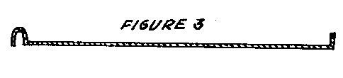
When the water table intersects the land surface, springs or swamps are formed (see Figure 3). During a
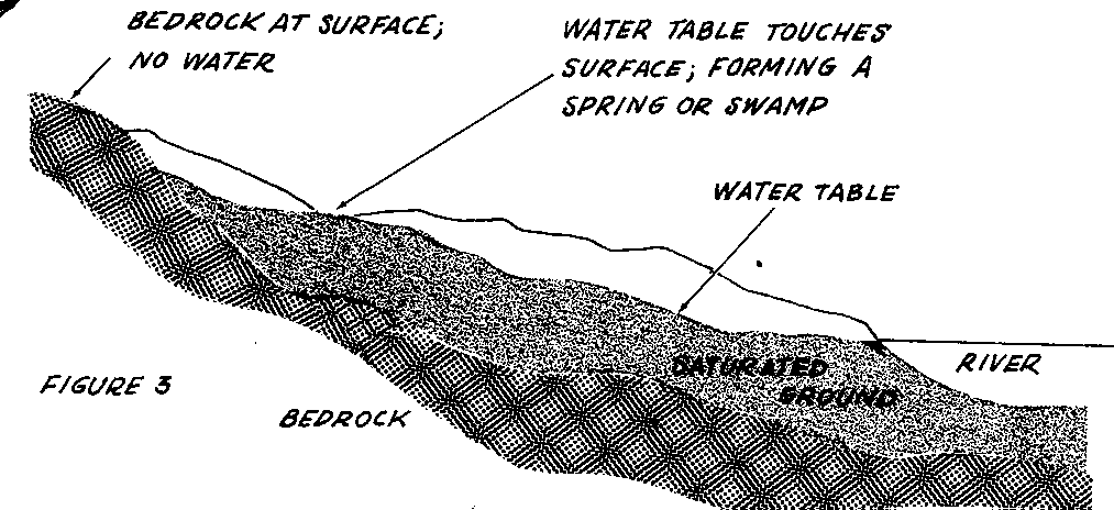
particularly wet season, the water table will come much closer to the land surface than it normally does and many new springs or swampy areas will appear. On the other hand, during a particularly dry season, the water table will be lower than normal and many springs will "dry up." Many shallow wells may also "go dry."
Flow of Water to Wells
A newly dug well fills with water a meter or so (a few feet) deep, but after some hard pumping it becomes dry. Has the well failed? Was it dug in the wrong place? More likely you are witnessing the phenomenon of drawdown, an effect every pumped well has on the water table (see Figure 4).
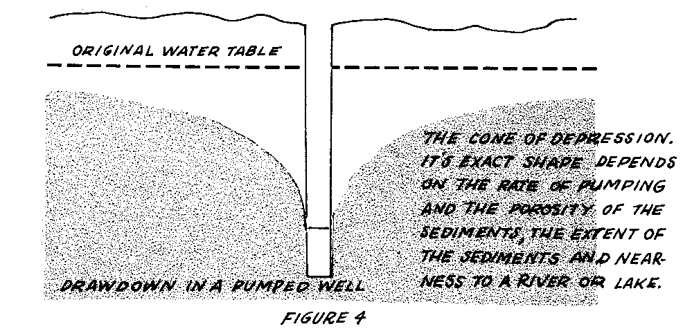
Because water flows through sediments slowly, almost any well can be pumped dry temporarily if it is pumped hard enough. Any pumping will lower the water level to some degree, in the manner shown in Figure 4. A serious problem arises only when the drawdown due to normal use lowers the water table below the level of the well.
After the well has been dug about a meter (several feet) below the water table, it should be pumped at about the rate it will be used to see if the flow into the well is adequate. If it is not sufficient, there may be ways to improve it. Digging the well deeper or wider will not only cut across more of the water-bearing layer to allow more flow into the well, but it will also enable the well to store a greater quantity of the water that may seep in overnight. If the well is still not adequate and can be dug no deeper, it can be widened further, perhaps lengthened in one direction, or more wells can be dug. The goal of all these methods is to intersect more of the water-bearing layers, so that the well will produce more water without lowering the water table to the bottom of the well.
Where to Dig a Well
Four important factors to consider in choosing a well site are:
- Nearness to Surface Water + Topography + Sediment Type + Nearness to Pollutants
Nearness to Surface Water
If there is surface water nearby, such as a lake or a river, locate the well as near to it as possible. It is likely to act as a source of water and keep the water table from being lowered as much as without it. This does not always work well, however, as lakes and slow-moving bodies of water generally have silt and slime on the bottom, which prevent water from entering the ground quickly.
There may not seem to be much point to digging a well near a river, but the filtering action of the soil will result in water that is cleaner and more free of bacteria. It may also be cooler than surface water. If the river level fluctuates during the year, a well will give cleaner water (than stream water) during the flood season, although ground water often gets dirty during and after a flood. A well will also give more reliable water during the dry season, when the water level may drop below the bed of the river. This method of water supply is used by some cities: a large well is sunk next to a lake or river and horizontal tunnels are dug to increase the flow.
Wells near the ocean, and especially those on islands, may have not only the problem of drawdown, but that of salt water encroachment (see Figure 5). The
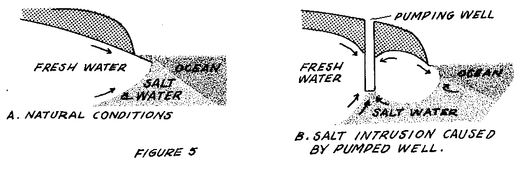
underground boundary between fresh and salt water generally slopes inland: Because salt water is heavier than fresh water, it flows in under it. If a well near the shore is used heavily, salt water may come into the well as shown. This should not occur in wells from which only a moderate amount of water is drawn.
Topography
Ground water, being liquid, gathers in low areas. Therefore, the lowest ground is generally the best place to drill or dig. If your area is flat or steadily sloping, and there is no surface water, one place is as good as another to start drilling or digging. If the land is hilly, valley bottoms are the best places to look for water.
You may know of a hilly area with a spring on the side of a hill. Such a spring could be the result of water moving through a layer of porous rock or a fracture zone in otherwise impervious rock. Good water sources can result from such features.
Sediment Type
Ground water occurs in porous or fractured rocks or sediments. Gravel, sand and sandstone are more porous than clay, unfractured shale and granite or "hard rock."
Figure 6 shows in a general way the relationship between the availability of

ground water (expressed by typical well discharges) and geologic material (sediments and various rock types). For planning the well discharge necessary for irrigating crops, a good rule of thumb for semi-arid climates-37.5cm (15") of precipitation a year-is a 1500- to 1900-liters (400 to 500 U.S. gallons)-per-minute well that will irrigate about 65 hectares (160 acres) for about six months. From Figure 6, we see that wells in sediments are generally more than adequate. However, enough ground water can be obtained from rock, if necessary, by drilling a number of wells. Deeper water is generally of better quality.
Sand and gravel are normally porous and clay is not, but sand and gravel can contain different amounts of silt and clay, which will reduce their ability to carry water. The only way to find the yield of a sediment is to dig a well and pump it.
In digging a well, be guided by the results of nearby wells and the effects of seasonal fluctuations on nearby wells. And keep an eye on the sediments in your well as it is dug. In many cases you will find that the sediments are in layers, some porous and some not. You may be able to predict where you will hit water by comparing the layering in your well with that of nearby wells.
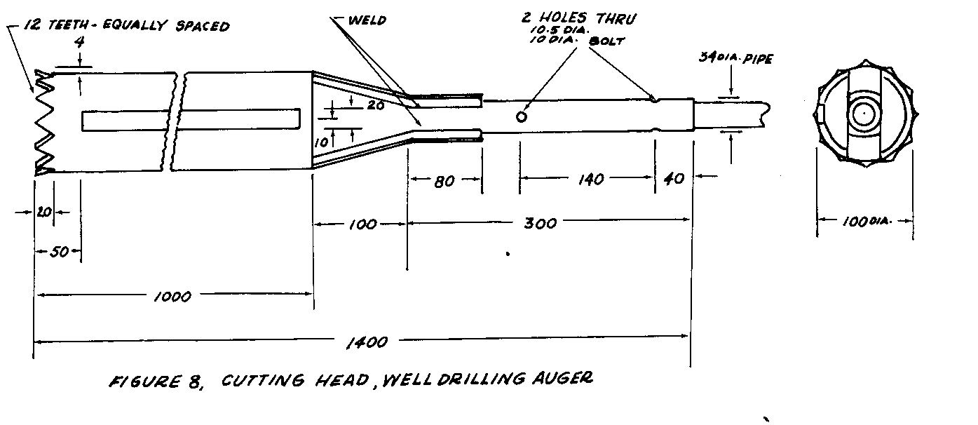
Figures 7, 8, and 9 illustrate several sediment situations and give guidelines on how deep to dig wells.

Aquifers (water bearing sediments) of Sand and Gravel. Generally yield 11,400 LPM (300 gpm) (but they may yield less depending on pump, well construction, and well development. Aquifers of Sand, Gravel, and Clay (Intermixed or Interbedded). Generally yield between 1900 LPM (500 gpm) and 3800 LPM (1000 gpm), but can yield more --between 3800 LPM (1000 gpm) and 11,400 LPM (3000 gpm)-- depending on the percentage of the constituents. Aquifers of Sand and Clay. Generally yield about 1900 LPM (500 gpm) but may yield as much as 3800 LPM (1000 gpm). Aquifers of Fractured Sandstone. Generally yield about 1900 LPM (500 gpm) but may yield more than 3800 LPM (1000 gpm) depending on the thickness of the sandstone and the degree and extent of fracturing (may also yield less than 1900 LPM (500 and gpm) if thin and poorly fractured or interbedded with clay or shale). Aquifers of Limestone. Generally yield between 38 LPM (10gpm) but have been known to yield more than 3800 LPM (1000 gpm) due to caverns or nearness of stream, etc. Aquifers of Granite and/or "Hard Rock." Generally yield 38 gpm (10gpm) and may yield less (enough for a small household). Aquifers of Shale. Yield less than 38 LPM (10gpm), not much good for anything except as a last resort.
Nearness to Pollutants
If pollution is in the ground water, it moves with it. Therefore, a well should always be uphill and 15 to 30 meters (50 to 100 feet) away from a latrine, barnyard, or other source of pollution. If the area is flat, remember that the flow of ground water will be downward, like a river, toward any nearby body of surface water. Locate a well in the upstream direction from pollution sources.
The deeper the water table, the less chance of pollution because the pollutants must travel some distance downward before entering ground water. The water is purified as it flows through the soil.
Extra water added to the pollutants will increase their flow into and through the soil, although it will also help dilute them. Pollution of ground water is more likely during the rainy than the dry season, especially if a source of pollution such as a latrine pit is allowed to fill with water. See also the Overview to the Sanitary Latrines section, p. 149. Similarly, a well that is heavily used will increase the flow of ground water toward it, perhaps even reversing the normal direction of ground-water movement. The amount of drawdown is a guide to how heavily the well is being used.
Polluted surface water must be kept out of the well pit. This is done by casing and sealing the well and providing good drainage around the well cover.
Well Casing and Seal
The purpose of casing and seating wells is to prevent contaminated surface water from entering the well or nearby ground water. As water will undoubtedly be spilled from any pump, the top of the well must be sealed with a concrete slab to let the water flow away rather than re-enter the well directly. It is also helpful to build up the pump area with soil to form a slight hill that will help drain away spilled water and rain water.
Casing is the term for the pipe, concrete or grout ring, or other material that supports the well wall. It is usually impermeable in the upper part of the well to keep out polluted water (see Figure 7) and may be perforated or absent in the
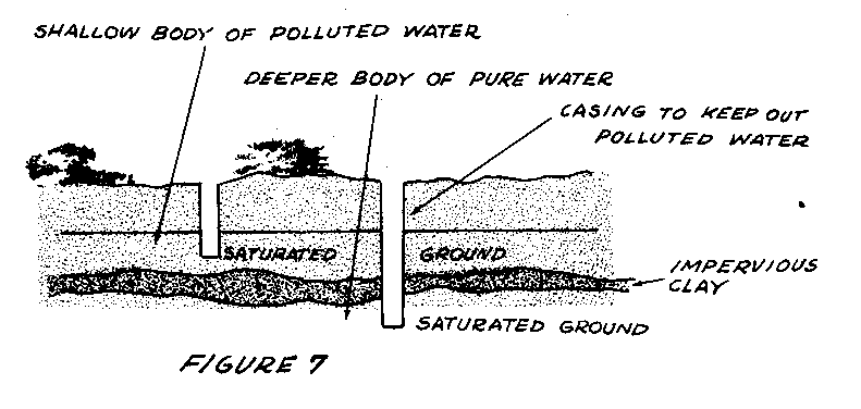
lower part of the well to let water enter. See also "Well Casing and Platforms," p. 12, and "Reconstructing Dug Wells," p. 57.
In loose sediment, the base of the well should consist of a perforated casing surrounded by coarse sand and small pebbles; otherwise, rapid pumping may bring into the well enough material to form a cavity and collapse the well itself. Packing the area around the well hole in the water-bearing layer with fine gravel will prevent sand from washing in and increase the effective size of the well. The ideal gradation is from sand to 6mm (1/4") gravel next to the well screen. In a drilled well it may be added around the screen after the pump pipe is installed.
Well Development
Well development refers to the steps taken after a well is drilled to ensure maximum flow and well life by preparing the sediments around the well. The layer of sediments from which the water is drawn often consists of sand and silt. When the well is first pumped, the fine material will be drawn into the well and make the water muddy. You will want to pump out this fine material to keep it from muddying the water later and to make the sediments near the well more porous. However, if the water is pumped too rapidly at first, the fine particles may collect against the perforated casing or the sand grains at the bottom of the well and block the flow of water into it.
A method for removing the fine material successfully is to pump slowly until the water clears, then at successively higher rates until the maximum of the pump or well is reached. Then the water level should be permitted to return to normal and the process repeated until consistently clear water is obtained.
Another method is surging, which is moving a plunger (an attachment on a drill rod) up and down in the well. This causes the water to surge in and out of the sedimentary layer and wash loose the fine particles, as well as any drilling mud stuck on the wall of the well. Coarse sediment washed into the well can be removed by a bailing bucket, or it may be left in the bottom of the well to serve as a filter.
Sources:
Anderson, K.E. Water Well Handbook. Rolla, Missouri: Missouri Water Wells Drillers Association, 1965.
Baldwin, H.L. and McGuinness, C.L. A Primer on Ground Water. Washington, D.C.: U.S. Government Printing Office, 1964.
Davis, S.N. and DeWiest, R.J.M. Hydrogeology. New York: Wiley & Sons, 1966.
Todd, D.K. Ground Water Hydrology. New York: Wiley & Sons, 1959.
Wagner, E.G. and Lanoix, J.N. Water Supply for Rural Areas and Small Communities. Geneva: World Health Organization, 1959.
Ground Water and Wells. Saint Paul, Minnesota: Edward E. Johnson, Inc., 1966.
Small Water Supplies, Bulletin No. 10. London: The Ross Institute, 1967.
U.S. Army. Wells. Technical Manual 5-297. Washington, D.C.: U.S. Government Printing Office, 1957.
TUBEWELLS
Where soil conditions permit, the tubewells described here will, if they have the necessary casing, provide pure water. They are much easier to install and cost much less than large diameter wells.
Tubewells will probably work well where simple earth borers or earth augers work (i.e., alluvial plains with few rocks in the soil), and where there is a permeable water-bearing layer 15 to 25 meters (50 to 80 feet) below the surface. They are sealed wells, and consequently sanitary, which offer no hazard to small children. The small amounts of materials needed keep the cost down. These wells may not yield enough water for a lane group, but they would be big enough for a family of a small group of families.
The storage capacity in small diameter wells is small. Their yield depends largely on the rate at which water flows from the surrounding soil into the well. From a saturated sand layer, the flow is rapid. Water flowing in quickly replaces water drawn from the well. A well that taps such a layer seldom goes dry. But even when water-bearing sand is not reached, a well with even a limited storage capacity may yield enough water for a household.
Well Casing and Platforms
In home or village wells, casing and platforms serve two purposes: (1) to keep well sides from caving in, and (2) to seal the well and keep any polluted surface water from entering it.
Two low-cost casing techniques are described here:
- Method A (see Figure 1), from an American Friends Service Committee (AFSC)
team in Rasulia, Madhya Pradesh, India.
- Method B, from an International Voluntary Services (IVS) team in Vietnam.
Method A
Tools and Materials
Casing pipe (from pump to water-bearing layer to below minimum water table)-Asbestos cement, tile, concrete, or even galvanized iron pipe will do Sand Gravel Cement Device for lowering and placing casing (see Figure 2)

Drilling rig - see "Tubewell Boring" Foot valve, cylinder, pipe, hand pump The well hole is dug as deep as possible into the water-bearing strata. The diggings are placed near the hole to make a mound, which later will serve to drain spilled water away from the well. This is important because backwash is one of the few sources of contamination for this type of well. The entire casing pipe below water level should be perforated with many small holes no larger than 5mm (3/16") in diameter. Holes larger than this will allow coarse sand to be washed inside and plug up the well. Fine particles of sand, however, are expected to enter. These should be small enough to be pumped immediately out through the pump. This keeps the well clear. The first water from the new well may bring with it large quantities of fine sand. When this happens, the first strokes should be strong and steady and continued until the water comes clear.
Perforated casing is lowered, bell end downward, into the hole using the device shown in Figure 2. When the casing is properly positioned, the trip cord is pulled and the next section prepared and lowered. Since holes are easily drilled in asbestos cement pipe, they can be wired together at the joint and lowered into the well. Be sure the bells point downward, since this will prevent surface water or backwash from entering the well without the purifying filtration effect of the soil; it will also keep sand and dirt from filling the well. Install the casing vertically and fill the remaining space with pebbles. This will hold the casing plumb. The casing should rise 30 to 60cm (1' to 2') above ground level and be surrounded with a concrete pedestal to hold the pump and to drain spilled water away from the hole. Casing joints within 3 meters (10 feet) of the surface should be sealed with concrete or bituminous material.
Method B
Plastic seems to be an ideal casing material, but because it was not readily available, the galvanized iron and concrete casings described here were developed in the Ban Me Thuot area of Vietnam.
Tools and Materials
Wooden V-block, 230cm (7 1/2') long (see Figure 3)
Angle iron, 2 sections, 230cm (7 1/2') long Pipe, 10cm (4") in diameter, 230cm (7 1/2') long Clamps Wooden mallet Soldering equipment Galvanized sheet metal: 0.4mm x 1m x 2m (0.01.6" x 39 1/2" x 79")
Plastic Casing
Black plastic pipe for sewers and drains was almost ideal. Its friction joints could be quickly slipped together and sealed with a chemical solvent. It seemed durable but was light enough to be lowered into the well by hand. It could be easily sawed or drilled to make a screen. Care must be taken to be sure that any plastic used is non-toxic.
Galvanized Sheet Metal Casing
Galvanized sheet metal was used to make casing similar to downspouting. A thicker gauge than the 0.4mm (0.016") available would have been preferable. Because the sheet metal would not last indefinitely if used by itself, the well hole was made oversize and the ring-shaped space around the casing was filled with a thin concrete mixture which formed a cast concrete casing and seal outside the sheet metal when it hardened.
The 1-meter x 2-meter (39 1/2" x 79") sheets were cut lengthwise into three equal pieces, which yielded three 2-meter (79") lengths of 10cm (4") diameter pipe.
The edges were prepared for making seams by clamping them between the two angle irons, then pounding with a wooden mallet to the shape shown in Figure 3.
The seam is made slightly wider at one end than at the other to give the pipe a slight taper, which allows successive lengths to be slipped a short distance inside one another.
The strips are rolled by bridging them over a 2-meter (79") V-shaped wooden block and applying pressure from above with a length of 5cm (2") pipe (see Figure 4).

The sheet metal strips are shifted from side to side over the V-block as they are being bent to produce as uniform a surface as possible. When the strip is bent enough, the two edges are hooked together and the 5cm (2") pipe is slipped inside. The ends of the pipe are set up on wooden blocks to form an anvil, and the seam is firmly crimped as shown in Figure 5.

After the seam is finished, any irregularities in the pipe are removed by applying pressure by hand or with the wooden mallet and pipe anvil. A local tinsmith and his helper were able to make six to eight lengths (12 to 16 meters) of the pipe per day. Three lengths of pipe were slipped together and soldered as they were made, and the remaining joints had to be soldered as the casing was lowered into the well.
The lower end of the pipe was perforated with a hand drill to form a screen. After the casing was lowered to the bottom of the well, fine gravel was packed around the perforated portion of the casing to above the water level. The cement grouting mortar used around the casings varied from pure cement to a 1:1 1/2 cement : sand ratio mixed with water to a very plastic consistency. The grout was put around the casing by gravity and a strip of bamboo about 10 meters (33 feet) long was used to "rod" the grout into place. A comparison of volume around the casing and volume of grouting used indicated that there may have been some voids left probably below the reach of the bamboo rod. These are not serious however, as long as a good seal is obtained for the first 8 to 10 meters (26 to 33 feet) down from the surface. In general, the greater proportion of cement used and the greater the space around the casing, the better seemed to be the results obtained. However, insufficient experience has been obtained to reach any final conclusions. In addition, economic considerations limit both of these factors.
Care must be taken in pouring the grout. If the sections of casing are not assembled perfectly straight, the casing, as a result, is not centered in the well and the pressure of the grouting is not equal all the way around. The casing may collapse. With reasonable care, pouring the grout in several stages and allowing it to set in-between should eliminate this. The grouting, however, cannot be poured in too many stages because a considerable amount sticks to the sides of the well each time, reducing the space for successive pourings to pass through.
This method can be modified for use in areas where the structure of the material through which the well is drilled is such that there is little or no danger of cave-in. In this situation, the casing serves only one purpose, as a sanitary seal. The well will be cased only about 8 meters (26 feet) down from the ground surface. To do this, the well is drilled to the desired depth with a diameter roughly the same as that of the casing. The well is then reamed out to a diameter 5 to 6cm (2" to 2 1/4") larger than the casing down to the depth the casing will go. A flange fitted at the bottom of the casing with an outside diameter about equal to that of the reamed hole will center the casing in the hole and support the casing on the shoulder where the reaming stopped. Grouting is then poured as in the original method. This modification (1) saves considerable costly material, (2) allows the well to be made a smaller diameter except near the top, (3) lessens grouting difficulties, and (4) still provides adequate protection against pollution.
Concrete Tile Casing
If the well is enlarged to an adequate diameter, precast concrete tile with suitable joints could be used as casing. This would require a device for lowering the tiles into the well one by one and releasing them at the bottom. Mortar would have to be used to seal the joints above the water level, the mortar being spread on each successive joint before it is lowered. Asbestos cement casing would also be a possibility where it was available with suitable joints.
No Casing
The last possibility would be to use no casing at all. It is felt that when finances or skills do not permit the well to be cased, there are certain circumstances under which an uncased well would be better than no well at all. This is particularly true in localities where the custom is to boil or make tea out of all water before drinking it, where sanitation is greatly hampered by insufficient water supply, and where small-scale hand irrigation from wells can greatly improve the diet by making gardens possible in the dry season.
The danger of pollution in an uncased well can be minimized by: (1) choosing a favorable site for the well and (2) making a platform with a drain that leads away from the well, eliminating all spilled water.
Such a well should be tested frequently for pollution. If it is found unsafe, a notice to this effect should be posted conspicuously near the well.
Well Platform
In the work in the Ban Me Thuot area, a flat 1.75-meter (5.7') square slab of concrete was used around each well. However, under village conditions, this did not work well. Large quantities of water were spilled, in part due to the enthusiasm of the villagers for having a plentiful water supply, and the areas around wells became quite muddy.
The conclusion was reached that the only really satisfactory platform would be a round, slightly convex one with a small gutter around the outer edge. The gutter should lead to a concreted drain that would take the water a considerable distance from the well. It is worth noting that in Sudan and other very arid areas such spillage from community wells is used to water vegetable gardens or community nurseries.
If the well platform is too big and smooth, there is a great temptation on the part of the villagers to do their laundry and other washing around the well. This should be discouraged. In villages where animals run loose it is necessary to build a small fence around the well to keep out animals, especially poultry and pigs, which are very eager to get water, but tend to mess up the surroundings.
Sources:
Koegel, Richard G. Report. Ban Me Thuot, Vietnam: International Voluntary Services, 1959. (Mimeographed.)
Mott, Wendell. Explanatory Notes on Tubewells. Philadelphia: American Friends Service Committee, 1956. (Mimeographed.)
Hand-Operated Drilling Equipment
Two methods of drilling a shallow tubewell with hand-operated equipment are described here: Method A, which was used by an American Friends Service Committee (AFSC) team in India, operates by turning an earth-boring auger. Method B, developed by an International Voluntary Services (IVS) team in Vietnam, uses a ramming action.
Earth Boring Auger
This simple hand-drilling rig can be used to dig wells 15 to 20cm (6" to 8") in diameter up to 15 meters (50') deep.
Tools and Materials
Earth auger, with coupling to attach to 2.5cm (1") drill line (see entry on tubewell earth augers) Standard weight galvanized steel pipe:
For Drill Line:
4 pieces: 2.5cm (1") in diameter and 3 meters (10') long (2 pieces have threads on one end only; others need no threads.) 2 pieces: 2.5cm (1") in diameter and 107cm (3 1/2") long
For Turning Handle:
2 pieces: 2.5cm (1") in diameter and 61cm (2') long 2.5cm (1") T coupling
For Joint A:
4 pieces: 32mm (1 1/4") in diameter and 30cm (1') long
Sections and Couplings for Joint B:
23cm (9") Section of 32mm (1 1/4") diameter (threaded at one end only) 35.5cm (14") Section of 38mm (1 1/2") diameter (threaded at one end only) Reducer coupling: 32mm to 25mm (1 1/4" to 1") Reducer coupling: 38mm to 25mm (1 1/2" to 1") 8 10mm (3/8") diameter hexagonal head machine steel bolts 45mm (1 3/4") long, with nuts 2 10mm (3/8") diameter hexagonal head machine steel bolts 5cm (2") long, with nuts 9 10mm (3/8") steel hexagonal nuts
For Toggle Bolt:
1 3mm (1/8") diameter countersink head iron rivet, 12.5mm (1/2") long 1 1.5mm (1/16") sheet steel, 10mm (3/8") x 25mm (1")
Drills: 3mm (1/8"), 17.5mm (13/16"), 8.75mm (13/32") Countersink Thread cutting dies, unless pipe is already threaded Small Tools: wrenches, hammer, hacksaw, files For platform: wood, nails, rope, ladder
Basically the method consists of rotating an ordinary earth auger. As the auger penetrates the earth, it fills with soil. When full it is pulled out of the hole and emptied. As the hole gets deeper, more sections of drilling line are added to extend the shaft. Joint A (Figures 1 and 2) is a simple method for attaching new

sections.
By building an elevated platform 3 to 3.7 meters (10 to 12 feet) from the ground, a 7.6-meter (25 foot) long section of drill line can be balanced upright. Longer lengths are too difficult to handle. Therefore, when the hole gets deeper than 7.6 meters (25 feet), the drill line must be taken apart each time the auger is removed for emptying. Joint B makes this operation easier. See Figures 1 and 3.
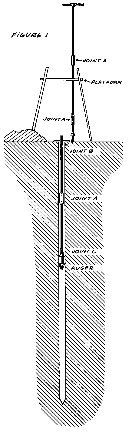
Joint C (see construction details for Tubewell Earth Auger) is proposed to allow rapid emptying of the auger. Some soils respond well to drilling with an auger that has two sides open. These are very easy to empty, and would not require Joint C. Find out what kinds of augers are successfully used in your area, and do a bit of experimenting to find the one best suited to your soil. See the entries on augers.
Joint A has been found to be faster to use and more durable than pipe threaded connectors. The pipe threads become damaged and dirty and are difficult to start. Heavy, expensive pipe wrenches get accidentally dropped into the well and are hard to get out. These troubles can be avoided by using a sleeve pipe fastened with two 10mm (3/8") bolts. Neither a small bicycle wrench nor the inexpensive bolts will obstruct drilling if dropped in. Be sure the 32mm (1 1/4") pipe will fit over your 25mm (1") pipe drill line before purchase. See Figure 2.

Four 3-meter (10') sections and two 107cm (3 1/2') sections of pipe are the most convenient lengths for drilling a 15-meter (50') well. Drill an 8.75mm (13/32") diameter hole through each end of all sections of drill line except those attaching to Joint B and the turning handle, which must be threaded joints. The holes should be 5cm (2") from the end.
When the well is deeper than 7.6 meters (25'), several features facilitate the emptying of the auger, as shown in Figures 3 and 4. First, pull up the full auger

until Joint B appears at the surface. See Figure 4A. Then put a 19mm (3/4")
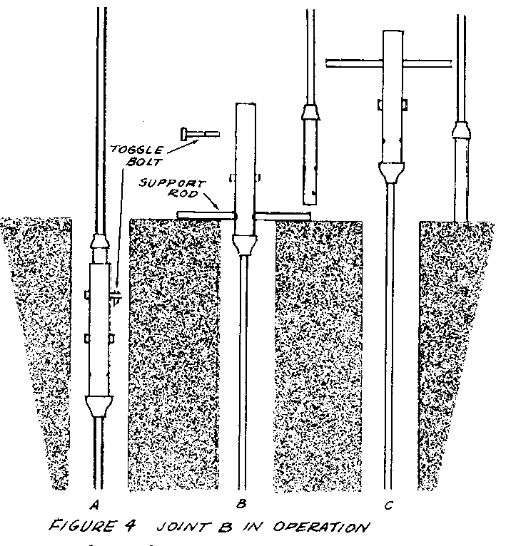
diameter rod through the hole. This allows the whole drill line to rest on it making it impossible for the part still in the well to fall in. Next remove the toggle bolt, lift out the top section of line and balance it beside the hole. See Figure 4B. Pull up the auger, empty it, and replace the section in the hole where it will be held by the 19mm (3/4") rod. See Figure 4C. Next replace the upper section of drill line. The 10mm (3/8") bolt acts as a stop that allows the holes to be easily lined up for reinsertion of the toggle bolt. Finally withdraw the rod and lower the auger for the next drilling. Mark the location for drilling the 8.75mm (13/32") diameter hole in the 32mm (1 1/4") pipe through the toggle bolt hole in the 38mm (1 1/2") pipe. If the hole is located with the 32mm (1 1/4") pipe resting on the stop bolt, the holes are bound to line up.
Sometimes a special tool is needed to penetrate a water-bearing sand layer, because the wet sand caves in as soon as the auger is removed. If this happens a perforated casing is lowered into the well, and drilling is accomplished with an auger that fits inside the casing. A percussion type with a flap, or a rotary type with solid walls and a flap are good possibilities. See the entries describing these devices. The casing will settle deeper into the sand as sand is dug from beneath it. Other sections of casing must be added as drilling proceeds. Try to penetrate the water bearing sand layer as far as possible (at least three feet-one meter). Ten feet (three meters) of perforated casing embedded in such a sandy layer will provide a very good flow of water.
Tubewell Earth Auger
This earth auger (Figure 5), which is similar to designs used with power drilling
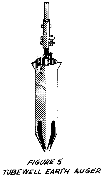
equipment, is made from a 15cm (6") steel tube.
The auger can be made without welding equipment, but some of the bends in the pipe and the bar can be made much more easily when the metal is hot (see Figure 6).
An open earth auger, which is easier to empty than this one, is better suited for some soils. This auger cuts faster than the Tubewell Sand Auger.
Tools and Materials
Galvanized pipe: 32mm (1 1/4") in diameter and 21.5cm (8 1/2") long Hexagonal head steel bolt: 10mm (3/8") in diameter and 5cm (2") long, with nut 2 hexagonal head steel bolts: 10mm (3/8") in diameter and 9.5cm (3 3/4") long 2 Steel bars: 1.25cm x 32mm x 236.5mm (1/2" x 1 1/4" x 9 5/16") 4 Round head machine screws: 10mm (3/8") in diameter and 32mm (1 1/4") long 2 Flat head iron rivets: 3mm (1/8") in diameter and 12.5mm (1/2") long Steel strip: 10mm x 1.5mm x 2.5cm (3/8" x 1/16" x 1") Steel tube: 15cm (6") outside diameter, 62.5cm (24 5/8") long Hand tools
Source:
U.S. Army and Air Force. Wells. Technical Manual 5-297, AFM 85-23. Washington, D.C.: U.S. Government Printing Office, 1957.
Tubewell Sand Auger
This sand auger can be used to drill in loose soil or wet sand, where an earth auger is not effective. The simple cutting head requires less force to turn than the Tubewell Earth Auger, but it is more difficult to empty.
A smaller version of the sand auger made to fit inside the casing pipe can be used to remove loose, wet sand.
The tubewell sand auger is illustrated in Figure 7. Construction diagrams are given in
Figure 8.

Tools and Materials
Steel tube: 15cm (6") outside diameter and 46cm (18") long Steel plate: 5mm x 16.5cm x 16.5cm (3/16" x 6 1/2" x 6 1/2") Acetylene welding and cutting equipment Drill
Source:
Wells, Technical Manual 5-297, AFM 85-23, U.S. Army and Air Force, 1957.
Tubewell Sand Bailer
The sand bailer <see figure 9> can be used to drill from inside a perforated well casing when a
bore goes into loose wet sand and the walls start to cave in. It has been used to make many tubewells in India.
Tools and Materials
Steel tube: 12.5cm (5") in diameter and 91.5cm (3') long Truck innertube or leather: 12.5cm (5") square Pipe coupling: 15cm to 2.5cm (5" to 1") Small tools
Repeatedly jamming this "bucket" into the well will remove sand from below the perforated casing, allowing the bucket to settle deeper into the sand layer. The casing prevents the walls from caving in. The bell is removed from the first section of casing; at least one other section rests on top of it to help force it down as digging proceeds. Try to penetrate the water bearing sand layer as far as possible: 3 meters (10') of perforated casing embedded in such a sandy layer will usually provide a very good flow of water.
Be sure to try your sand "bucket" in wet sand before attempting to use it at the bottom of your well.
Source:
Explanatory Notes on Tubewells, Wendell Mott, American Friends Service Committee, Philadelphia, Pennsylvania, 1956 (Mimeographed).
Ram Auger
The equipment described here has been used successfully in the Ban Me Thuot area of Vietnam. One of the best performances was turned in by a crew of three inexperienced mountain tribesmen who drilled 20 meters (65') in a day and a half. The deepest well drilled was a little more than 25 meters (80'); it was completed, including the installation of the pump, in six days. One well was drilled through about 11 meters (35') of sedimentary stone.
Tools and Materials
For tool tray:
Wood: 3cm x 3cm x 150cm (1 1/4" x 1 1/4" x 59") Wood: 3cm x 30cm x 45cm (1 1/4" x 12"x 17 3/4")
For safety rod:
Steel rod: 1cm (3/8") in diameter, 30cm (12") long Drill Hammer Anvil Cotter pin
For auger support:
Wood: 4cm x 45cm x 30cm (1 1/3" x 17 3/4" x 12") Steel: 10cm x 10cm x 4mm (4" x 4" x 5/32")
Location of the Well
Two considerations are especially important for the location of village wells: (1) the average walking distance for the village population should be as short as possible; (2) it should be easy to drain spilled water away from the site to avoid creating a mudhole.
In the Ban Me Thuot area, the final choice of location was in all cases left up to the villagers. Water was found in varying quantities at all the sites chosen. (See "Getting Ground Water from Wells and Springs.")
Starting to Drill
A tripod is set up over the approximate location for the well (see Figure 1). Its
legs are set into shallow holes with dirt packed around them to keep them from moving. To make sure the well is started exactly vertically, a plumb bob (a string with a stone tied to it is good enough) is hung from the auger guide on the tripod's crossbar to locate the exact starting point. It is helpful to dig a small starting hole before setting up the auger.
Drilling
Drilling is accomplished by ramming the auger down to penetrate the earth and then rotating it by its wooden handle to free it in the hole before lifting it to repeat the process. This is a little awkward until the auger is down 30cm to 60cm (1' to 2') and should be done carefully until the auger starts to be guided by the hole itself. Usually two or three people work together with the auger. One system that worked out quite well was to use three people, two working while the third rested, and then alternate.
As the auger goes deeper it will be necessary from time to time to adjust the handle to the most convenient height. Any wrenches or other small tools used should be tied by means of a long piece of cord to the tripod so that if they are accidentally dropped in the well, they can easily be removed. Since the soil of the Ban Me Thuot area would stick to the auger, it was necessary to keep a small amount of water in the hole at all times for lubrication.
Emptying the Auger
Each time the auger is rammed down and rotated, it should be noted how much penetration has been obtained. Starting with an empty auger the penetration is greatest on the first stroke and becomes successively less on each following one as the earth packs more and more tightly inside the auger. When progress becomes too slow it is time to raise the auger to the surface and empty it. Depending on the material being penetrated, the auger may be completely full or have 30cm (1') or less of material in it when it is emptied. A little experience will give one a "feel" for the most efficient time to bring up the auger for emptying. Since the material in the auger is hardest packed at the bottom, it is usually easiest to empty the auger by inserting the auger cleaner through the slot in the side of the auger part way down and pushing the material out through the top of the auger in several passes. When the auger is brought out of the hole for emptying, it is usually leaned up against the tripod, since this is faster and easier than trying to lay it down.
Coupling and Uncoupling Extensions
The extensions are coupled by merely slipping the small end of one into the large end of the other and pinning them together with a 10mm (3/8") bolt. It has been found sufficient and time-saving to just tighten the nut finger-tight instead of using a wrench.
Each time the auger is brought up for emptying, the extensions must be taken apart. For this reason the extensions have been made as long as possible to minimize the number of joints. Thus at a depth of 18.3 meters (60'), there are only two joints to be uncoupled in bringing up the auger.
For the sake of both safety and speed, use the following procedure in coupling and uncoupling. When bringing up the auger, raise it until a joint is just above the ground and slip the auger support (see Figures 2 and 3) into place, straddling
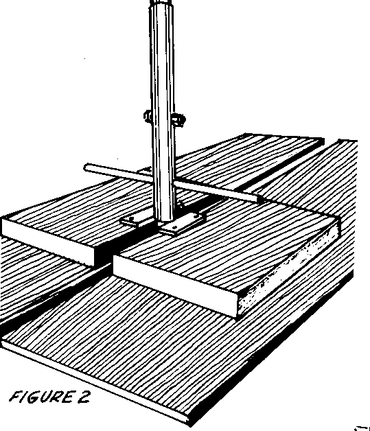
the extension so that the bottom of the coupling can rest on the small metal plate. The next step is to put the safety rod (see Figure 4)
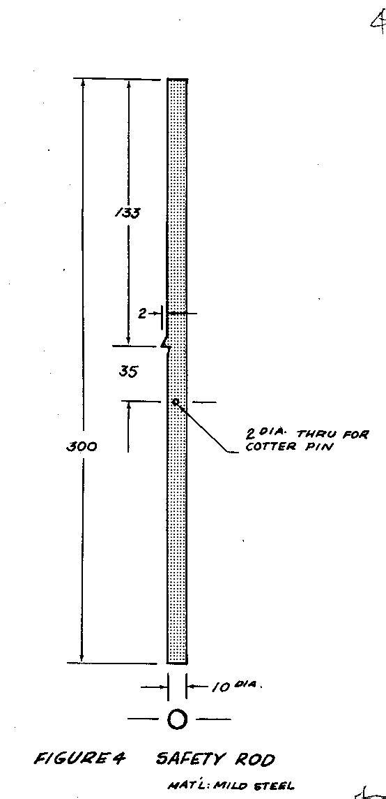
through the lower side in the coupling and secure it with either a cotter pin or a piece of wire. The purpose of the safety rod is to keep the auger from falling into the well if it should be knocked off the auger support or dropped while being raised.
Once the safety rod is in place, remove the coupling bolt and slip the upper extension out of the lower. Lean the upper end of the extension against the tripod between the two wooden pegs in the front legs, and rest the lower end on the tool tray (see Figures 5 and 6). The reason for putting the extensions on the tool tray
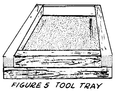
is to keep dirt from sticking to the lower ends and making it difficult to put the extensions together and take them apart.
To couple the extensions after emptying the auger, the procedure is the exact reverse of uncoupling.
Drilling Rock
When stone or other substances the auger cannot penetrate are met, a heavy drilling bit must be used.
Depth of Well
The rate at which water can be taken from a well is roughly proportional to the depth of the well below the water table as long as the well keeps going into water-bearing ground. However, in village wells where water can only be raised slowly by handpump or bucket, this is not usually of major importance. The important point is that in areas where the water table varies from one time of year to another the well must be deep enough to give sufficient water at all times.
Information on the water table variation may be obtained from already existing wells, or it may be necessary to drill a well before any information can be obtained. In the latter case the well must be deep enough to allow for a drop in the water table.
Source:
Report by Richard G. Koegel, International Voluntary Services, Ban Me Thuot, Vietnam, 1959 (Mimeographed).
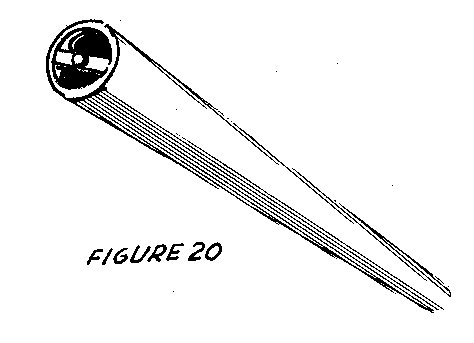
Equipment <see figure 7>
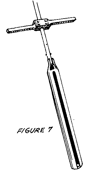
The following section gives construction details for the well-drilling equipment used with the ram auger:
- Auger, Extensions, and Handle + Auger Cleaner + Demountable Reamer + Tripod and Pulley + Bailing Bucket + Bit for Drilling rock
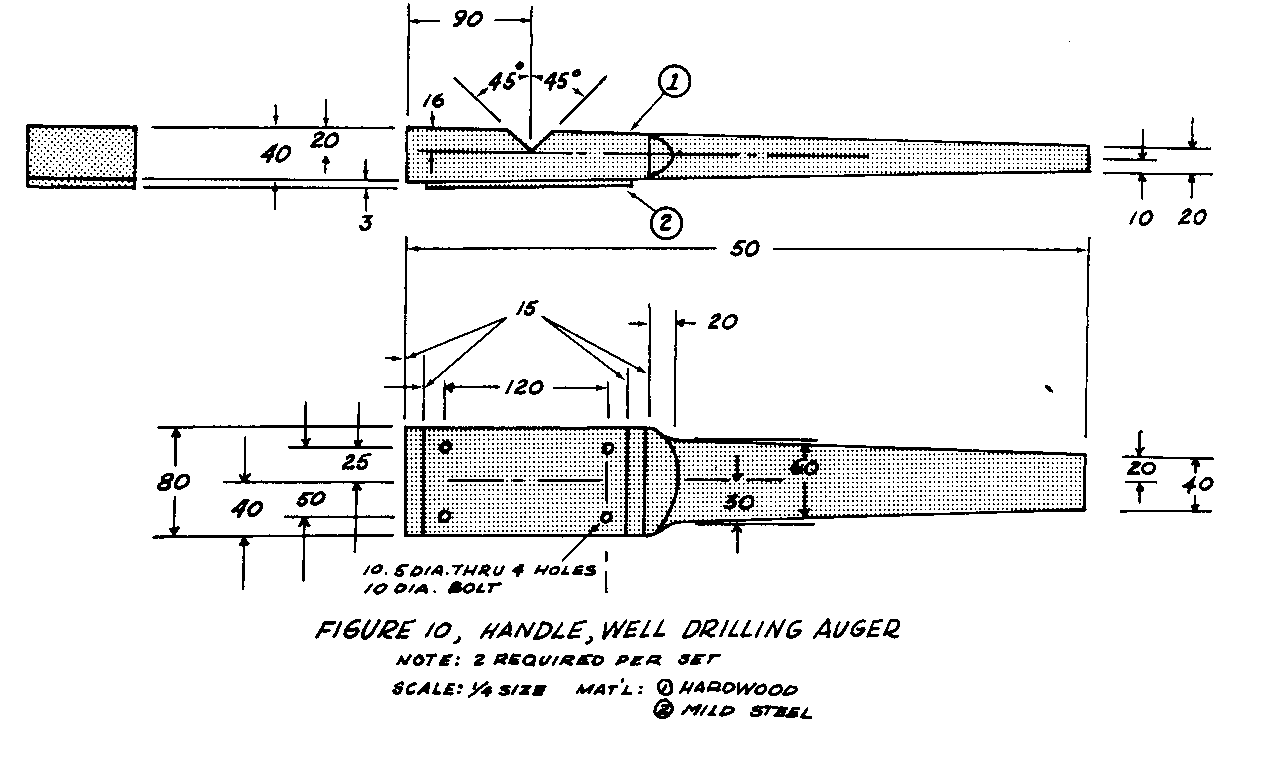
Auger, Extensions, and Handle
The auger is hacksawed out of standard-weight steel pipe about 10cm (4") in diameter (see Figure 8). Lightweight tubing is not strong enough. The extensions
(see Figure 9) and handle (see Figure 10) make it possible to bore deep holes.

Tools and Materials
Pipe: 10cm (4") in diameter, 120cm (47 1/4") long, for auger Pipe: 34mm outside diameter (1" inside diameter); 3 or 4 pieces 30cm (12") long, for auger and extension socket Pipe: 26mm outside diameter (3/4" inside diameter); 3 or 4 pieces 6.1 or 6.4 meters (20' or 21') long, for drill extensions Pipe: 10mm outside diameter (1/2" inside diameter); 3 or 4 pieces 6cm (2 3/8") long Hardwood: 4cm x 8cm x 50cm (1 1/2" x 3 1/8" x 19 3/4"), for handle Mild steel: 3mm x 8cm x 15cm (1/8" x 3 1/8" x 6") 4 Bolts: 1cm (3/8") in diameter and 10cm (4") long 4 Nuts
Hand tools and welding equipment
In making the auger, a flared-tooth cutting edge is cut in one end of the 10cm pipe. The other end is cut, bent, and welded to a section of 34mm outside-diameter (1" inside-diameter) pipe, which forms a socket for the drill line extensions. A slot that runs nearly the length of the auger is used for removing soil from the auger. Bends are made stronger and more easily and accurately when the steel is hot. At first, an auger with two cutting lips similar to a post-hole auger was used; but it became plugged up and did not cut cleanly. In some soils, however, this type of auger may be more effective.
Auger Cleaner
Soil can be removed rapidly from the auger with this auger cleaner (see Figure 11).
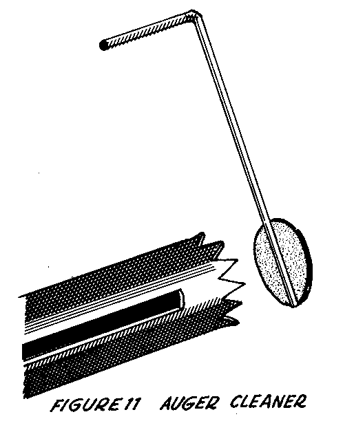
Figure 12 gives construction details.
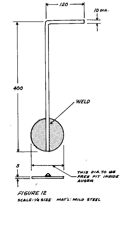
Tools and Materials
Mild steel: 10cm (4") square and 3mm (1/8") thick Steel rod: 1cm (3/8") in diameter and 52cm (20 1/2") long Welding equipment Hacksaw File
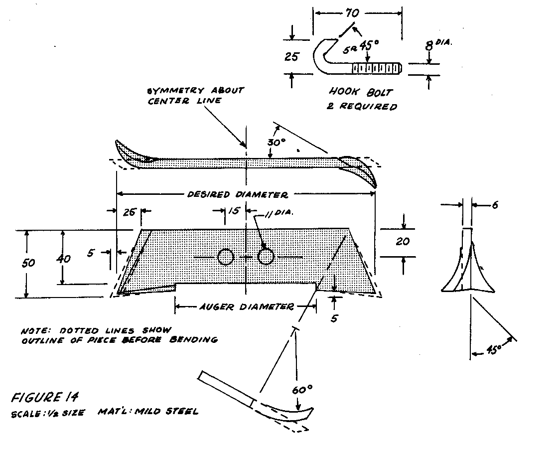
Demountable Reamer
If the diameter of a drilled hole has to be made bigger, the demountable reamer described here can be attached to the auger.
Tools and Materials
Mild steel: 20cm x 5cm x 6mm (6" x 2" x 1/4"), to ream a well diameter of 19cm (7 1/2") 2 Bolts: 8mm (5/16") in diameter and 10cm (4") long Hacksaw Drill File Hammer Vise
The reamer is mounted to the top of the auger with two hook bolts (see Figure 13).
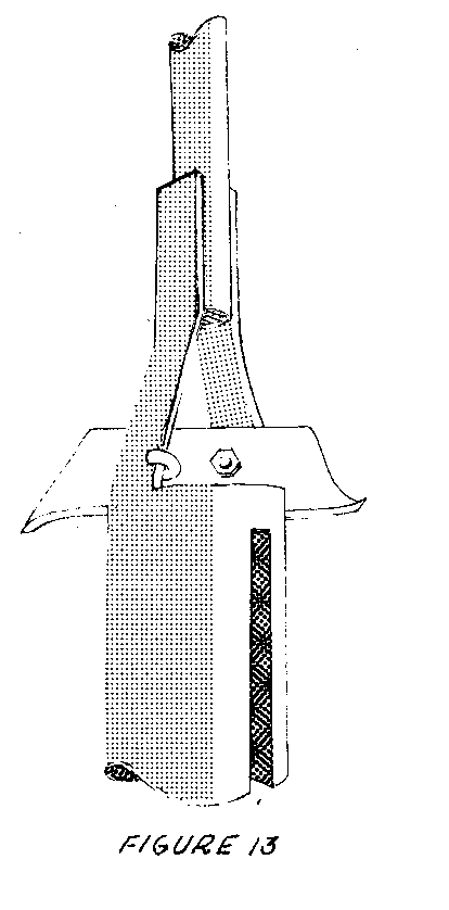
It is made from a piece of steel 1cm (1/2") larger than the desired well diameter (see Figure 14).
After the reamer is attached to the top of the auger, the bottom of the auger is plugged with some mud or a piece of wood to hold the cuttings inside the auger.
In reaming, the auger is rotated with only slight downward pressure. It should be emptied before it is too full so that not too many cuttings will fall to the bottom of the well when the auger is pulled up.
Because the depth of a well is more important than the diameter in determining the flow and because doubling the diameter means removing four times the amount of earth, larger diameters should be considered only under special circumstances. (See "Well Casing and Platforms," page 12.)
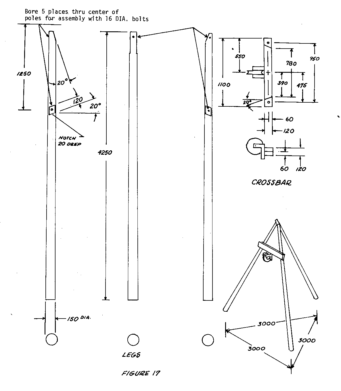
Tripod and Pulley
The tripod (see Figures 15 and 16), which is made of poles and assembled with
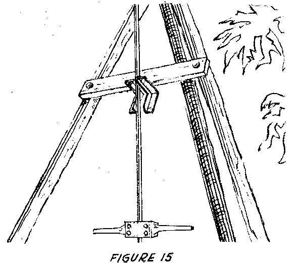
when it extends far above ground; (2) to provide a mounting for the pulley (see Figures 17 and 19)
place for leaning long pieces of casing, pipe for pumps, or auger extensions while they are being put into or taken out of the well.
When a pin or bolt is put through the holes in the two ends of the "L"-shaped pulley bracket (see Figures 15 and 18) that extend horizontally beyond the front

formed.
To keep the extensions from falling when they are leaned against the tripod, two 30cm (12") long wooden pegs are driven into drilled holes near the top of the tripod's two front legs (see Figure 19).
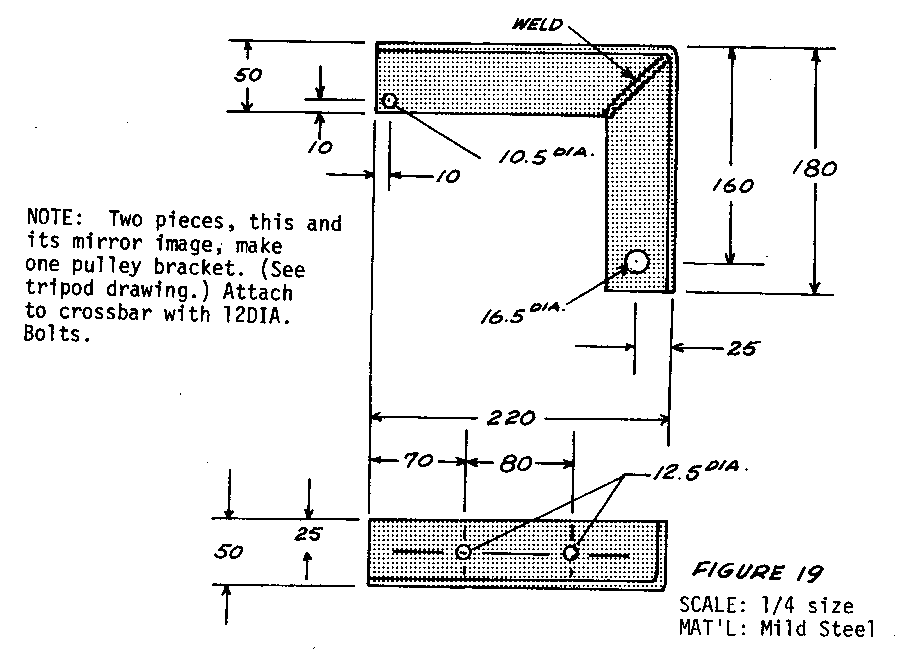
Tools and Materials
3 Poles: 15cm (3") in diameter and 4.25 meters (14') long Wood for cross bar: 1.1 meter (43 1/2") x 12cm (4 3/4") square For pulley wheel: Wood: 25cm (10") in diameter and 5cm (2") thick Pipe: 1.25cm (1/2") inside diameter, 5cm (2") long Axle bolt: to fit close inside 1.25cm (1/2") pipe Angle iron: 80cm (31 1/2") long, 50cm (19 3/4") webs, 5mm (3/16") thick 4 Bolts: 12mm (1/2") in diameter, 14cm (5 1/2") long; nuts and washers Bolt: 16mm (5/8") in diameter and 40cm (15 3/4") long; nuts and washer 2 Bolts: 16mm (5/8") in diameter and 25cm (9 7/8") long; nuts and washers Bore 5 places through center of poles for assembly with 16mm bolts
Bailing Bucket
The bailing bucket can be used to remove soil from the well shaft when cuttings are too loose to be removed with the auger.
Tools and Materials
Pipe: about 8.5cm (3 3/8") in diameter, 1 to 2cm (1/2" to 3/4") smaller in diameter than the auger, 180cm (71") long Steel rod: 10mm (3/8") in diameter and 25cm (10") long; for bail (handle) Steel plate: 10cm (4") square, 4mm (5/32") thick Steel bar: 10cm x 1cm x 5mm (4" x 3/8" x 3/16") Machine screw: 3mm (1/8") diameter by 16mm (5/8") long; nut and washer Truck innertube: 4mm (5/32") thick, 10mm (3/8") square Welding equipment Drill Hacksaw Hammer Vise File Rope
Both standard weight pipe and thin-walled tubing were tried for the bailing bucket. The former, being heavier, was harder to use, but did a better job and stood up better under use. Both the steel bottom of the bucket and the rubber valve should be heavy because they receive hard usage. The metal bottom is reinforced with a crosspiece welded in place (see Figures 20 and 21).
When water is reached and the cuttings are no longer firm enough to be brought up in the auger, the bailing bucket must be used to clean out the well as work progresses.
For using the bailing bucket the pulley is mounted in the pulley bracket with a 16mm (5/8") bolt as axle. A rope attached to the bailing bucket is then run over the pulley and the bucket is lowered into the well. The pulley bracket is so designed that the rope coming off the pulley lines up vertically with the well, so that there is no need to shift the tripod.
The bucket is lowered into the well, preferably by two people and allowed to drop the last meter or meter and one-half (3 to 5 feet) so that it will hit the bottom with some speed. The impact will force some of the loose soil at the bottom of the well up into the bucket. The bucket is then repeatedly raised and dropped 1 to 2 meters (3 to 6 feet) to pick up more soil. Experience will show how long this should be continued to pick up as much soil as possible before raising and emptying the bucket. Two or more people can raise the bucket, which should be dumped far enough from the well to avoid messing up the working area.
If the cuttings are too thin to be brought up with the auger but too thick to enter the bucket, pour a little water down the well to dilute them.
Bit for Drilling Rock
The bit described here has been used to drill through layers of sedimentary stone up to 11 meters (36') thick.
Tools and Materials
Mild steel bar: about 7cm (2 3/4") in diameter and about 1.5 meters (5') long, weighing about 80kg (175 pounds) Stellite (a very hard type of tool steel) insert for cutting edge Anvil and hammers, for shaping Steel rod: 2.5cm x 2cm x 50cm (1" x 3/4" x 19 3/4") for bail Welding equipment
The drill bit for cutting through stone and hard formations is made from the 80kg (175-pound) steel bar (see Figures 22 and 23). The 90-degree cutting edge is hard-surfaced
handle) for attaching a rope or cable is welded to the top. The bail should be large enough to make "fishing" easy if the rope breaks. A 2.5cm (1") rope was used at first, but this was subject to much wear when working in mud and water. A 1cm (3/8") steel cable was substituted for the rope, but it was not used enough to be able to show whether the cable or the rope is better. One advantage of rope is that it gives a snap at the end of the fall which rotates the bit and keeps it from sticking. A swivel can be mounted between the bit and the rope or cable to let the bit rotate.
If a bar this size is difficult to find or too expensive, it may be possible, depending on the circumstances, to make one by welding a short steel cutting end onto a piece of pipe, which is made heavy enough by being filled with concrete.
In using the drilling bit, put the pulley in place as with the bailing bucket, attach the bit to its rope or cable, and lower it into the well. Since the bit is heavy, wrap the rope once or twice around the back leg of the tripod so that the bit cannot "get away" from the workers with the chance of someone being hurt or the equipment getting damaged. The easiest way to raise and drop the bit is to run the rope through the pulley and then straight back to a tree or post where it can be attached at shoulder height or slightly lower. Workers line up along the rope and raise the bit by pressing down on the rope; they drop it by allowing the rope to return quickly to its original position (see Figure 24). This requires five
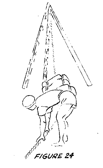
to seven workers, occasionally more. Frequent rests are necessary, usually after every 50 to 100 strokes. Because the work is harder near the ends of the rope than in the middle, the positions of the workers should be rotated to distribute the work evenly.
A small amount of water should be kept in the hole for lubrication and to mix with the pulverized stone to form a paste that can be removed with a bailing bucket. Too much water will slow down the drilling.
The speed of drilling, of course, depends on the type of stone encountered. In the soft water-bearing stone of the Ban Me Thuot area it was possible to drill several meters (about 10 feet) per day. However, when hard stone such as basalt is encountered, progress is measured in centimeters (inches). The decision must then be made whether to continue trying to penetrate the rock or to start over in a new location. Experience in the past has indicated that one should not be too hasty in abandoning a location, since on several occasions what were apparently thin layers of hard rock were penetrated and drilling then continued at a good rate.
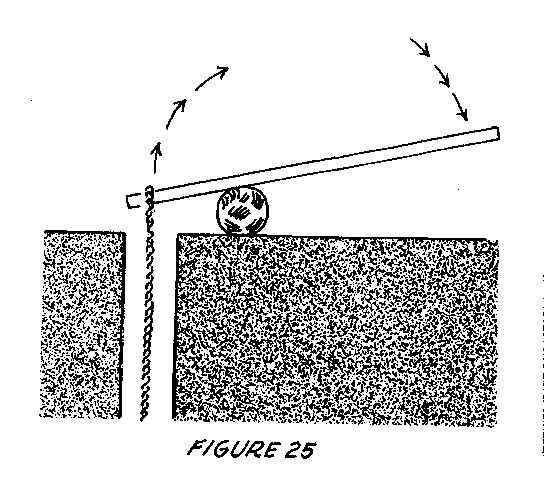
Occasionally the bit may become stuck in the well and it will be necessary to use a lever arrangement consisting of a long pole attached to the rope to free it (see Figure 25).
Alternatively, a windlass may be used, consisting of a horizontal pole used to wrap the rope around a vertical pole pivoted on the ground and held in place by several workers (see Figure 26). If these fail, it may be necessary to
rent or borrow a chain hoist. A worn rope or cable may break when trying to retrieve a stuck bit. If this happens, fit a hook to one of the auger extensions, attach enough extensions together to reach the desired depth, and after hooking the bit, pull with the chain hoist. A rope or cable may also be used for this purpose, but are considerably more difficult to hook onto the bit.
Drilling Mechanically
The following method can be used for raising and dropping the bit mechanically:
- Jack up the rear wheel of a car and replace the wheel with a small drum (or use the rim as a pulley). + Take the rope that is attached to the bit, come from the tripod on the pulley, and wrap the rope loosely around the drum. + Pull the unattached end of the rope taut and set the drum in motion. The rope will move with the drum and raise the bit. + Let the end of the rope go slack quickly to drop the bit. It will probably be necessary to polish and/or grease the drum.
Dry Bucket Well Drilling
The dry bucket method is a simple and quick method of drilling wells in dry soil that is free of rocks. It can be used for 5cm to 7.5cm (2" to 3") diameter wells in which steel pipe is to be installed. For wells that are wider in diameter, it is a quick method of removing dry soil before completing the bore with a wet bucket, tubewell sand bailer, or tubewell sand auger.
A 19.5-meter (64') hole can be dug in less than three hours with this method, which works best in sandy soil, according to the author of this entry, who has drilled 30 wells with it.
Tools and Materials
Dry bucket Rope: 16mm (5/8") or 19mm (3/4") in diameter and 6 to 9 meters (20' to 30') longer than the deepest well to be drilled 3 Poles: 20cm (4") in diameter at large end and 3.6 to 4.5 meters (12' to 15') long Chain, short piece Pulley Bolt: 12.5mm (1/2") in diameter and 30 to 35cm (12" to 14") long (long enough to reach through the upper ends of the three poles)
A dry bucket is simply a length of pipe with a bail or handle welded to one end and a slit cut in the other.
The dry bucket is held about 10cm (several inches) above the ground, centered above the hole location and then dropped (see Figure 1). This drives a small
amount of soil up into the bucket. After this is repeated two or three times, the bucket is removed, held to one side and tapped with a hammer or a piece of iron to dislodge the soil. The process is repeated until damp soil is reached and the bucket will no longer remove soil.
To make the dry bucket, you will need the following tools and materials:
Hacksaw File Iron rod: 10mm (3/8") or 12.5mm (1/2") in diameter and 30cm (1') long Iron pipe: slightly larger in diameter than the largest part of casing to be put in the well (usually the coupling) and 152cm (5') long
Bend the iron rod into a U-shape small enough to slide inside the pipe. Weld it in place as in Figure 2.
File a gentle taper on the inside of the opposite end to make a cutting edge (see Figure 3).
Cut a slit in one side of the sharpened end of the pipe (see Figure 2).
Source:
John Brelsford, VITA Volunteer, New Holland, Pennsylvania
Driven Wells
A pointed strainer called a well point, properly used, can quickly and cheaply drive a sanitary well, usually less than 7.6 meters (25') deep. In soils where the driven well is suitable, it is often the cheapest and fastest way to drill a sanitary well. In heavy soils, particularly clay, drilling with an earth auger is faster than driving with a well point.
Tools and Materials
Well point and driving cap (see Figure 1):

usually obtainable through mail order houses from the United States and elsewhere Pipe: 3cm (1") in diameter Heavy hammer and wrenches Pipe compound Special pipe couplings and driving arrangements are desirable but not necessary
Driven wells are highly successful in coarse sand where there are not too many rocks and the water table is within 7 meters (23') of the surface. They are usually used as shallow wells where the pump cylinder is at ground level. If conditions for driving are very good, 10cm (4") diameter points and casings that can accept the cylinder of a deep well can be driven to depths of 10 - 15 meters (33' to 49'). (Note that suction pumps generally cannot raise water beyond 10 meters.)
The most common types of well points are:
- a pipe with holes covered by a screen and a brass jacket with holes. For general use, a #10 slot or 60 mesh is recommended. Fine sand requires a finer screen, perhaps a #6 slot or 90 mesh;
- a slotted steel pipe with no covering screen, which allows more water to enter but is less rugged.
Before starting to drive the point, make a hole at the site with hand tools. The hole should be plumb and slightly larger in diameter than the well point.
The joints of the drive pipe must be carefully made to prevent thread breakage and assure airtight operation. Clean and oil the threads carefully and use joint compound and special drive couplings when available. To ensure that joints stay tight, give the pipe a fraction of a turn after each blow, until the top joint is permanently set. Do not twist the whole string and do not twist and pound at the same time. The latter may help get past stones, but soon will break the threads and make leaky joints.
Be sure the drive cap is tight and butted against the end of the pipe (see Figure 2).
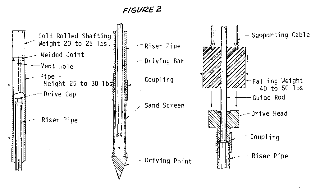
check with a plumb bob to see that the pipe is vertical. Test it occasionally and keep it straight by pushing on the pipe while driving. Hit the drive cap squarely each time or you may damage the equipment.
Several techniques can help avoid damage to the pipe. The best way is to drive with a steel bar that is dropped inside the pipe and strikes against the inside of the steel well point. It is retrieved with a cable of rope. Once water enters the well, this method does not work.
Another way is to use a driver pipe, which makes sure that the drive cap is hit squarely. A guide rod can be mounted on top of the pipe and weight dropped over it, or the pipe itself can be used to guide a falling weight that strikes a special drive clamp.
The table in Figure 3 will help identify the formations being penetrated. Experience

is needed, but this may help you to understand what is happening. When you think that the water-bearing layer has been reached, stop driving and attach a handpump to try the well.
Usually, easier driving shows that the water-bearing level has been reached, especially in coarse sand. If the amount of water pumped is not enough, try driving a meter or so (a few feet) more. If the flow decreases, pull the point back until the point of greatest flow is found. The point can be raised by using a lever arrangement like a fence-post jack, or, if a drive-monkey is used, by pounding the pipe back up.
Sometimes sand and silt plug up the point and the well must be "developed" to clear this out and improve the flow. First try hard, continuous pumping at a rate faster than normal. Mud and fine sand will come up with the water, but this should clear in about an hour. It may help to allow the water in the pipe to drop back down, reversing the flow periodically. With most pitcher pumps this is easily accomplished by lifting the handle very high; this opens the check valve, allowing air to enter, and the water rushes back down the well.
If this does not clear up the flow, there may be silt inside the point. This can be removed by putting a 19mm (3/4") pipe into the well and pumping on it. Either use the pitcher pump or quickly and repeatedly raise and lower the 19mm (3/4") pipe. By holding your thumb over the top of the pipe on the upstroke, a jet of muddy water will result on each downstroke. After getting most of the material out, return to direct pumping. Clean the sand from the valve and cylinder of the pump after developing the well. If you have chosen too fine a screen, it may not be possible to develop the well successfully. A properly chosen screen allows the fine material to be pumped out, leaving a bed of coarse gravel and sand that provides a highly porous and permeable water-gathering area.
The final step is to fill in the starting borehole with puddle clay or, if clay is not available, with well-tamped earth. Make a solid, water-proof pump platform (concrete is best) and provide a place for spilled water to drain away.
Source:
Wagner, E.G. and Lanoix, J.N. Water Supply for Rural Areas and Small Communities. Geneva: World Health Organization, 1959.
DUG WELLS <see figure 1>
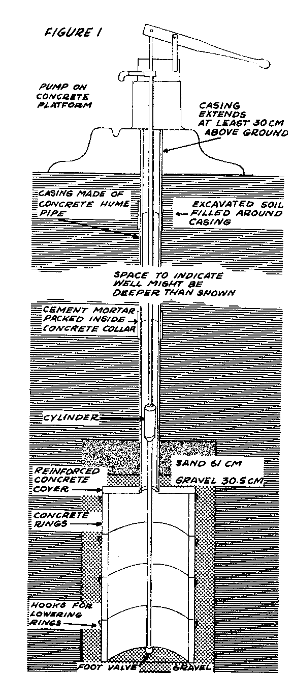
A village well must often act as a reservoir, because at certain hours of the day the demand for water is heavy, whereas during the night and the heat of the day there is no call on the supply. What is suggested here is to make the well large enough to allow the water slowly percolating in to accumulate when the well is not in use in order to have an adequate supply when demand is heavy. For this reason wells are usually made 183 to 213cm (6' to 7') in diameter.
Wells cannot store rainy season water for the dry season, and there is seldom any reason for making a well larger in diameter than 213cm (7').
The depth of a well is much more important than the diameter in determining the amount of water that can be drawn when the water level is low. A deep, narrow well will often provide more water than a wide shallow one.
Remember that tubewells are much easier to construct than dug wells, and should be used if your region allows their construction and an adequate amount of water can be drawn from them during the busy hours (see section on Tubewells).
Deep dug wells have several disadvantages. The masonry lining needed is very expensive. Construction is potentially very dangerous; workers should not dig deeper than one and a half meters without shoring up the hole. An open well is very easily contaminated by organic matter that falls in from the surface and by the buckets used to lift the water. There is an added problem of disposing of the great quantity of soil removed from a deep dug well.
Sealed Dug Well
The well described here has an underground concrete tank that is connected to the surface with a casing pipe, rather than a large-diameter lining as described in the preceding entry. The advantages are that it is relatively easy to build, easy to seal, takes up only a small surface area, and is low in cost.
Many of these wells were installed in India by an American Friends Service Committee team there; they perform well unless they are not deep enough or sealed and capped properly.
Tools and Materials
4 reinforced concrete rings with iron hooks for lowering, 91.5cm (3') in diameter 1 reinforced concrete cover with a seating hole for casing pipe Washed gravel to surround tank: 1.98 cubic meters (70 cubic feet) Sand for top of well: 0.68 cubic meters (24 cubic feet) Concrete pipe: 15cm (6") in diameter, to run from the top of the tank cover to at least 30.5cm (1') above ground Concrete collars: for joints in the concrete pipe Cement: 4.5kg (10 pounds) for mortar for pipe joints Deep-well pump and pipe Concrete base for pump Tripod, pulleys, rope for lowering rings Special tool for positioning casing when refilling, see "Positioning Casing Pipe," below Digging tools, ladders, rope
A villager in Barpali, India, working with an American Friends Service Committee unit there, suggested that they make a masonry tank at the bottom of the well, roof it over, and draw the water from it with a pump. The resulting sealed well has many advantages:
- It provides pure water, safe for drinking.
- It presents no hazard of children falling in.
- Drawing water is easy, even for small children.
- The well occupies little space, a small courtyard can accommodate it.
- The cost of installation is greatly reduced.
- The labor involved is much reduced.
- There is no problem of getting rid of excavated soil, since most of it is replaced.
- The casing enables the pump and pipe to be easily removed for servicing.
- The gravel and sand surrounding the tank provide an efficient filter to prevent silting, allow a large surface area for percolating water to fill the tank, and increase the effective stored volume in the tank.
On the other hand, compared to a well where people draw their own buckets or other containers of water, there are three minor disadvantages: only one person can pump at a time, the pump requires regular maintenance, and a certain amount of technical skill is required to make the parts used in the well and to install them properly.
A well is dug 122cm (4') in diameter and about 9 meters (30') deep. The digging should be done in the dry season, after the water table has dropped to its lowest level. There should be a full 3 meter (10') reaccumulation of water within 24 hours after the well has been bailed or pumped dry. Greater depth is, of course, desirable.
Spread 15cm (6") of clean, washed gravel or small rock over the bottom of the well. Lower the four concrete rings and cover into the well and position them there to form the tank. A tripod of strong poles with block and tackle is needed to lower the rings, because they weigh about 180kg (400 pounds) each. The tank formed by the rings and cover is 183cm (6') high and 91.5cm (3') in diameter. The cover has a round opening which forms a seat for the casing pipe and allows the suction pipe to penetrate to about 15cm (6") from the gravel bottom.
The first section of concrete pipe is positioned in the seat and grouted (mortared) in place. It is braced vertically by a wooden plug with four hinged arms to brace against the sides of the wall. Gravel is packed around the concrete rings and over the top of the cover till the gravel layer above the tank is at least 15cm (6") deep. This is then covered with 61cm (2') of sand. Soil removed from the well is then shoveled back until the shaft is filled within 15cm (6") of the top of the first section of casing. The next section of casing is then grouted in place, using a concrete collar made for this purpose. The well is filled and more sections of casing added until the casing extends at least 30cm (1') above the surrounding soil level.
The soil that will not pack back into the well can be used to make a shallow hill around the casing to encourage spilled water to drain away from the pump. A concrete cover is placed on the casing and a pump installed.
If concrete or other casing pipe cannot be obtained, a chimney made of burned bricks and sand-cement mortar will suffice. The pipe is somewhat more expensive, but much easier to install.
Source:
A Safe Economical Well. Philadelphia: American Friends Service Committee, 1956 (Mimeographed).
Deep Dug Well
Untrained workers can safely dig a deep sanitary well with simple, light equipment, if they are well supervised. The basic method is outlined here.
Tools and Materials
Shovels, mattocks Buckets Rope--deep wells require wire rope Forms--steel, welded and bolted together Tower with winch and pulley Cement Reinforcing rod Sand Aggregate Oil
The hand dug well is the most widespread of any kind of well. Unfortunately, in many places these wells are dug by people unfamiliar with good sanitation methods and become infected by parasitic and bacterial disease. By using modern methods and materials, dug wells can safely be made 60 meters (196.8') deep and will give a permanent source of pure water.
Experience has shown that for one person, the average width of a round well for best digging speed is 1 meter (3 1/4'). However, 1.3 meters (4 1/4') is best for two workers digging together and they dig more than twice as fast as one person. Thus, two workers in the larger hole is usually best.
Dug wells always need a permanent lining (except in solid rock, where the best method is usually to drill a tubewell).
The lining prevents collapse of the hole, supports the pump platform, stops entrance of contaminated surface water, and supports the well intake, which is the part of the well through which water enters. It is usually best to build the lining while digging, since this avoids temporary supports and reduces danger of cave-ins.
Dug wells are lined in two ways: (1) where the hole is dug and the lining is built in its permanent place and (2) where sections of lining are added to the top and the whole lining moves down as earth is removed from beneath it. The second method is called caissoning; often a combination of both is best (Figure 2.)
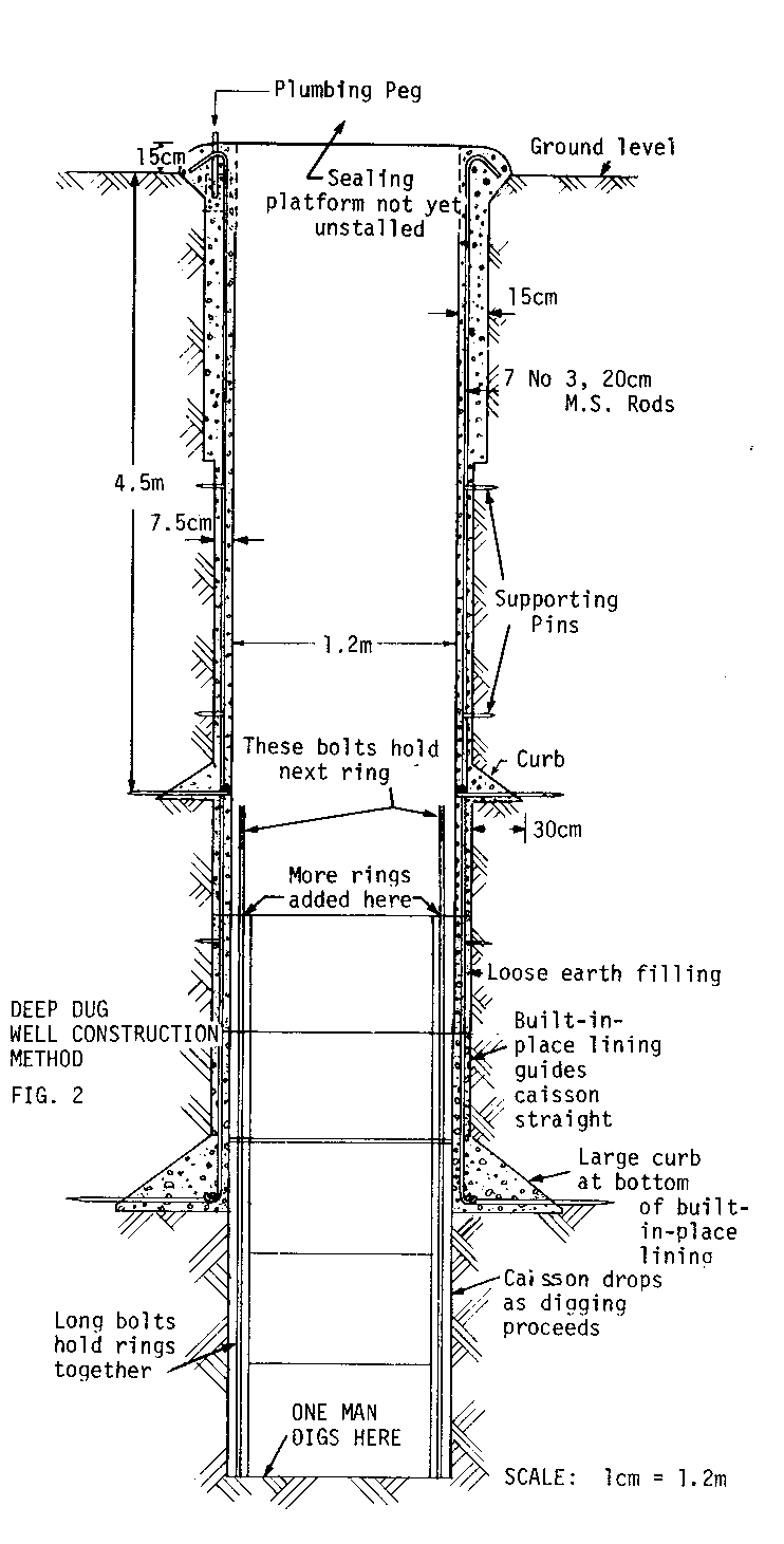
If possible, use concrete for the lining because it is strong, permanent, and made mostly of local materials. It can also be handled by unskilled workers with good speed and results. (See section on Concrete Construction).
Masonry and brickwork are widely used in many countries and can be very satisfactory if conditions are right. In bad ground, however, unequal pressures can make them bulge or collapse. Building with these materials is slow and a thicker wall is required than with concrete. There is also always the danger of movement during construction in loose sands or swelling shale before the mortar has set firmly between the bricks or stones.
Wood and steel are not good for lining wells. Wood requires bracing, tends to rot and hold insects, and sometimes makes the water taste bad. Worst of all, it will not make the well watertight against contamination. Steel is seldom used because it is expensive, rusts quickly, and if it is not heavy enough is subject to bulging and bending.
The general steps in finishing the first 4.6 meters (15') are:
- set up a tripod winch over cleared, level ground and mark reference points for plumbing and measuring the depth of the well.
- have two workers dig the well while another raises and unloads the dirt until the well is exactly 4.6 meters (15') deep.
- trim the hole to size using a special jig mounted on the reference points.
- place the forms carefully and fill one by one with tamped concrete.
After this is done, dig to 9.1 meters (30'), trim and line this part also with concrete. A 12.5cm (5") gap between the first and second of these sections is filled with pre-cut concrete that is grouted (mortared) in place. Each lining is self-supporting as it has a curb. The top of the first section of lining is thicker than the second section and extends above the ground to make a good foundation for the pump housing and to make a safe seal against ground water.
This method is used until the water-bearing layer is reached; there an extra-deep curb is constructed. From this point on, caissoning is used.
Caissons are concrete cylinders fitted with bolts to attach them together. They are cast and cured on the surface in special molds, prior to use. Several caissons are lowered into the well and assembled together. As workers dig, the caissons drop lower as earth is removed from beneath them. The concrete lining guides the caissons.
If the water table is high when the well is dug, extra caissons are bolted in place so that the well can be finished by a small amount of digging, and without concrete work, during the dry season.
Details on plans and equipment for this process are found in Water Supply for Rural Areas and Small Communities, by E. G. Wagner and J. N. Lanoix, World Health Organization, 1959.
Reconstructing Dug Wells
Open dug wells are not very sanitary, but they can often be rebuilt by relining the top 3 meters (10') with a watertight lining, digging and cleaning the well and covering it. This method involves installation of a buried concrete slab; see Figure 3
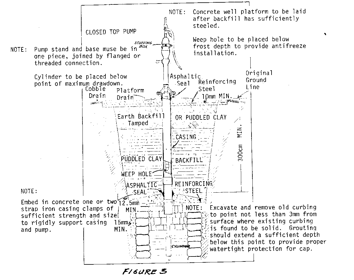
for construction details.
Tools and Materials
Tools and materials for reinforced concrete A method for entering the well Pump and drop pipe
Before starting, check the following:
- Is the well dangerously close to a privy or other source of contamination? Is it close to a water source? Is it desirable to dig a new well elsewhere instead of cleaning this one? Could a privy be moved, instead?
- Has the well ever gone dry? Should you deepen it as well as clean it?
- Surface drainage should generally slope away from the well and there should be effective disposal of spilled water.
- What method will you use to remove the water and what will it cost?
- Before entering the well to inspect the old lining, check for a lack of oxygen by lowering a lantern or candle. If the flame remains lit, it is reasonably safe to enter the well. If the flame goes out, the well is dangerous to enter. Tie a rope around the person entering the well and have two strong workers on hand to pull him out in case of accident.
Relining the Wall
The first job is to prepare the upper 3 meters (10') of the lining for concrete by removing loose rock and chipping away old mortar with a chisel, as deep as possible (see Figure 4). The next task is to clean out and deepen the well, if that
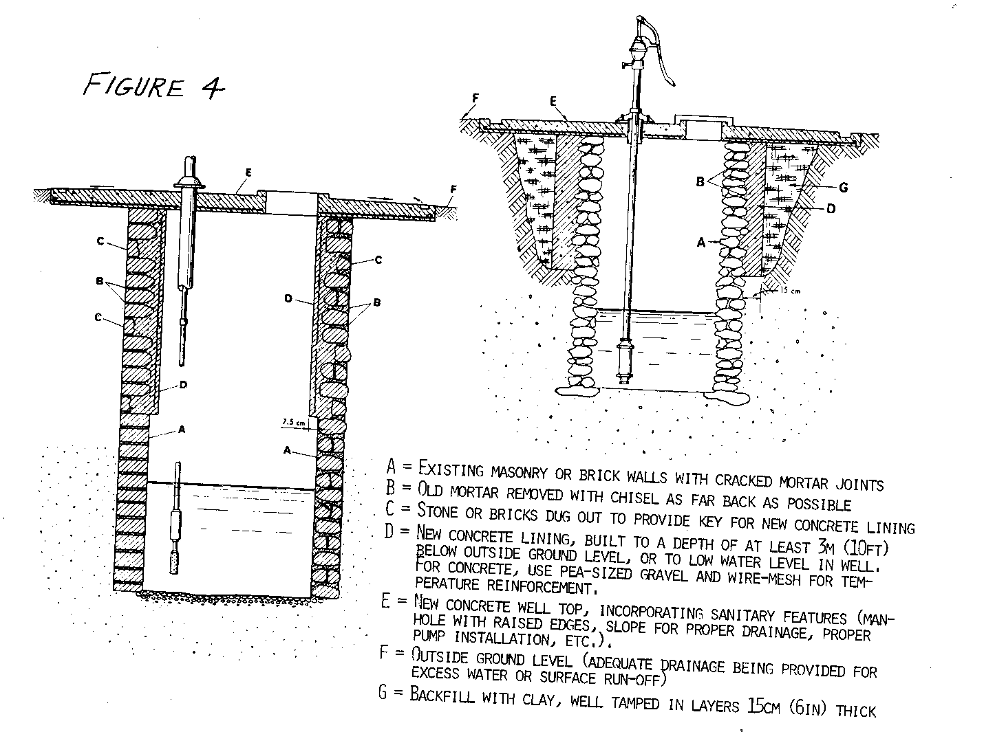
is necessary. All organic matter and silt should be bailed out. The well may be dug deeper, particularly during the dry season, with the methods outlined in "Deep Dug Wells." One way to increase the water yield is to drive a well point deeper into the water-bearing soil. This normally will not raise the level of water in the well, but may make the water flow into the well faster. The well point can be piped directly to the pump, but this will not make use of the reservoir capacity of the dug well.
The material removed from the well can be used to help form a mound around the well so water will drain away from the opening. Additional soil will usually be needed for this mound. A drain lined with rock should be provided to take spilled water away from the concrete apron that covers the well.
Reline the well with concrete troweled in place over wire mesh reinforcement. The largest aggregate should be pea-sized gravel and the mix should be fairly rich with concrete, using no more than 20-23 liters (5 1/2 to 6 gallons) of water to a 43kg (94 pound) sack of cement. Extend the lining 70cm (27 1/2") above the original ground surface.
Installing the Cover and Pump
Cast the well cover so that it makes a watertight seal with the lining to keep surface impurities out. The cover will also support the pump. Extend the slab out over the mound about a meter (a few feet) to help drain water away from the site. Make a manhole and space for the drop pipe of the pump. Mount the pump off center so there is room for the manhole. The pump is mounted on bolts cast into the cover. The manhole must be 10cm (4") higher than the surface of the slab. The manhole cover must overlap by 5cm (2") and should be fitted with a lock to prevent accidents and contamination. Be sure that the pump is sealed to the slab.
Disinfecting the Well
Disinfect the well by using a stiff brush to wash the walls with a very strong solution of chlorine. Then add enough chlorine in the well to make it about half the strength of the solution used on the walls. Sprinkle this last solution all over the surface of the well to distribute it evenly. Cover the well and pump up the water until the water smells strongly of chlorine. Let the chlorine remain in the pump and well for one day and then pump it until the chlorine is gone.
Have the well water tested several days after disinfection to be sure that it is pure. If it is not, repeat the disinfection and testing. If it is still not pure, get expert advice.
Sources:
Wagner, E.G. and Lanoix, J.N. Water Supply for Rural Areas and Small Communities. Geneva: World Health Organization, 1959.
Manual of Individual Water Supply Systems, Public Health Service Publication No. 24. Washington, D.C.: Department of Health and Human Services.
SPRING DEVELOPMENT
Springs, particularly in sandy soil, often make excellent water sources, but they should be dug deeper, sealed, protected by a fence, and piped to the home. Proper development of a spring will increase the flow of ground water and lower the chances of contamination from surface water. If fissured rock or limestone are present, get expert advice before attempting to develop the spring.
Springs occur where water, moving through porous and saturated underground layers of soil (aquifer), emerges at the ground surface. They can be either:
- Gravity seepage, where the water bearing soil reaches the surface over an impermeable layer, or
- Pressure or artesian, where the water, under pressure and trapped by a hard layer of soil, finds an opening and rises to the surface. (In some parts of the world, all springs are called artesian.)
The following steps should be considered in developing springs:
1) Observe the seasonal flow variations over a period of a year if possible.
2) Determine the type of spring-seepage or artesian-by digging a small hole. An earth auger with extensions is the most suitable tool for that job. It may not be possible to reach the underlying impermeable layer.
3) Have chemical and biological tests made on samples of the water.
Dig a small hole near the spring to learn the depth of the hard layer of soil and to find out whether the spring is gravity seepage or pressure. Check uphill and nearby for sources of contamination. Test the water to see if it must be purified before being used for drinking. A final point: Find out if the spring runs during long dry spells.
For gravity-fed springs, the soil is usually dug to the hard, underlying layers and a tank is made with watertight concrete walls on all but the uphill side (see Figures 1 and 2).

The opening on the uphill side should be lined with porous concrete or stone without mortar, so that it will admit the gravity seepage water. It can be backfilled with gravel and sand, which helps to keep fine materials in the water-bearing soil from entering the spring. If the hard soil cannot be reached easily, a concrete cistern is built that can be fed by a perforated pipe placed in the water-bearing layer of earth. With a pressure spring, all sides of the tank are made of watertight reinforced concrete, but the bottom is left open. The water enters through the bottom.
Read the section in this handbook on cisterns before developing your spring. No matter how the water enters your tank, you must make sure the water is pure by:
- building a complete cover to stop surface pollution and keep out sunlight, which causes algae to grow.
- installing a locked manhole with at least a 5cm (2") overlap to prevent entrance of polluted ground water.
- installing a screened overflow that discharges at least 15cm (6") above the ground. The water must land on a cement pad or rock surface to keep the water from making a hole in the ground and to ensure proper drainage away from the spring.
- arranging the spring so that surface water must filter through at least 3 meters (10') of soil before reaching the ground water. Do this by making a diversion ditch for surface water about 15 meters (50') or more from the spring. Also, if necessary, cover the surface of the ground near the spring with a heavy layer of soil or clay to increase the distances that rainwater must travel, thus ensuring that it has to filter through 3 meters (10') of soil.
- making a fence to keep people and animals away from the spring's immediate surroundings. The suggested radius is 7.6 meters (25').
- installing a pipeline from the overflow to the place where the water is to be used.
Before using the spring, disinfect it thoroughly by adding chlorine or chlorine compounds. Shut off the overflow to hold the chlorine solution in the well for 24 hours. If the spring overflows even though the water is shut off, arrange to add chlorine so that it remains strong for at least 30 minutes, although 12 hours would be much safer. After the chlorine is flushed from the system have the water tested. (See section on "Superchlorination.")
Sources:
Wagner, E.G. and Lanoix, J.N. Water Supply for Rural Areas and Small Communities. Geneva: World Health Organization, 1959.
Manual of Individual Water Supply Systems, Public Health Service Publication No. 24. Washington, D.C.: U.S. Department of Health and Human Services.
Acknowledgements
John M. Jenkins III, VITA Volunteer, Marrero, Louisiana Ramesh Patel, VITA Volunteer, Albany, New York William P. White, VITA Volunteer, Brooklyn, Connecticut
Water Lifting and Transport
OVERVIEW
Once a source of water has been found and developed, four basic questions must be answered:
1. What is the rate of flow of the water in your situation? 2. Between what points must the water be transported? 3. What kind and size of piping is needed to transport the required flow? 4. What kind of pump, if any, is necessary to produce the required flow?
The information in this section will help you to answer the third and fourth questions, once you have determined the answers to the first two.
Moving Water
The first three entries in this section discuss the flow of water in small streams, partially filled pipes, and when the height of the reservoir and size of pipe are known. They include equations and alignment charts (also called nomographs) that give simple methods of estimating the flow of water under the force of gravity, that is, without pumping. The fourth tells how to measure flow by observing the spout from a horizontal pipe.
Four entries follow on piping, including a discussion of pipes made of bamboo.
You will note that in the alignment charts here and elsewhere, the term "nominal diameter, inches, U.S. Schedule 40" is used along with the alternate term, "inside diameter in centimeters," in referring to pipe size.
Pipes and fittings are usually manufactured to a standard schedule of sizes. U.S. Schedule 40, the most common in the United States, is also widely used in other countries. When one specifies "2-inch Schedule 40," one automatically specifies the pressure rating of the pipe and its inside and outside diameters (neither of which, incidentally, is actually 2"). If the schedule is not known, measure the inside diameter and use this for flow calculations.
Lifting Water
Next, several entries follow the steps required to design a water-pumping system with piping. The first entry in this group, "Pump Specifications: Choosing or Evaluating a Pump," presents all the factors that must be considered in selecting a pump. Fill out the form included there and make a piping sketch, whether you plan to send it to a consultant for help or do the design and selection yourself.
The first pieces of information needed for selecting pump type and size are: (1) the flow rate of water needed and (2) the head or pressure to be overcome by the pump. The head is composed of two parts: the height to which the liquid must be raised, and the resistance to flow created by the pipe walls (friction-loss).
The friction-loss head is the most difficult factor to measure. The entry "Determining Pump Capacity and Horsepower Requirements" describes how to select the economic pipe size(s) for the flow desired. With the pipe(s) selected one must then calculate the friction-loss head. The entry "Estimating Flow Resistance of Pipe Fittings" makes it possible to estimate extra friction caused by constrictions of pipe fittings. With this information and the length of pipe, it is possible to estimate the pump power requirement using the entry, "Determining Pump Capacity and Horsepower Requirements."
These entries have another very important use. You may already have a pump and wonder "Will it do this job?" or "What size motor should I buy to do this job with the pump I have?" The entry "Pump Specifications: Choosing or Evaluating a Pump" can be used to collect all the information on the pump and on the job you want it to do. With this information, you can ask a consultant or VITA if the pump can be used or not.
There are many varieties of pumps for lifting water from where it is to where it is to be delivered. But for any particular job, there are probably one or two kinds of pumps that will serve better than others. We will discuss here only two broad classes of pumps: lift pumps and force pumps.
A lift or suction pump is located at the top of a well and raises water by suction. Even the most efficient suction pump can create a negative pressure of only 1 atmosphere: theoretically, it could raise a column of water 10.3m (34') at sea level. But because of friction losses and the effects of temperature, a suction pump at sea level can actually lift water only 6.7m to 7.6m (22' to 25'). The entry "Determining Lift Pump Capability" explains how to find out the height a lift pump will raise water at different altitudes with different water temperatures.
When a lift pump is not adequate, a force pump must be used. With a force pump, the pumping mechanism is placed at or near the water level and pushes the water up. Because it does not depend on atmospheric pressure, it is not limited to a 7.6m (25') head.
Construction details are given for two irrigation pumps that can be made at the village level. An easy-to-maintain pump handle mechanism is described. Use of the hydraulic ram, a self-powered pump, is described.
Finally, there are entries on Reciprocating Wire Power Transmission for Water Pumps, and on Wind Energy for Water Pumping. Further details on pumps can be found in the publications listed below and in the Reference section at the back of the book.
Margaret Crouch, ed. Six Simple Pumps. Arlington, Virginia: Volunteers in Technical Assistance, 1982.
Molenaar, Aldert. Water Lifting Devices for Irrigation. Rome: Food and Agriculture Organization, 1956.
Small Water Supplies. London: The Ross Institute, The London School of Hygiene and Tropical Medicine, 1967.
WATER TRANSPORT
Estimating Small Stream Water Flow
A rough but very rapid method of estimating water flow in small streams is given here. In looking for water sources for drinking, irrigation, or power generation, one should survey all the streams available. If sources are needed for use over a long period, it is necessary to collect information throughout the year to determine flow changes-especially high and low flows. The number of streams that must be used and the flow variations are important factors in determining the necessary facilities for utilizing the water.
Tools and Materials
Timing device, preferably watch with second hand Measuring tape Float (see below) <see figure 1>
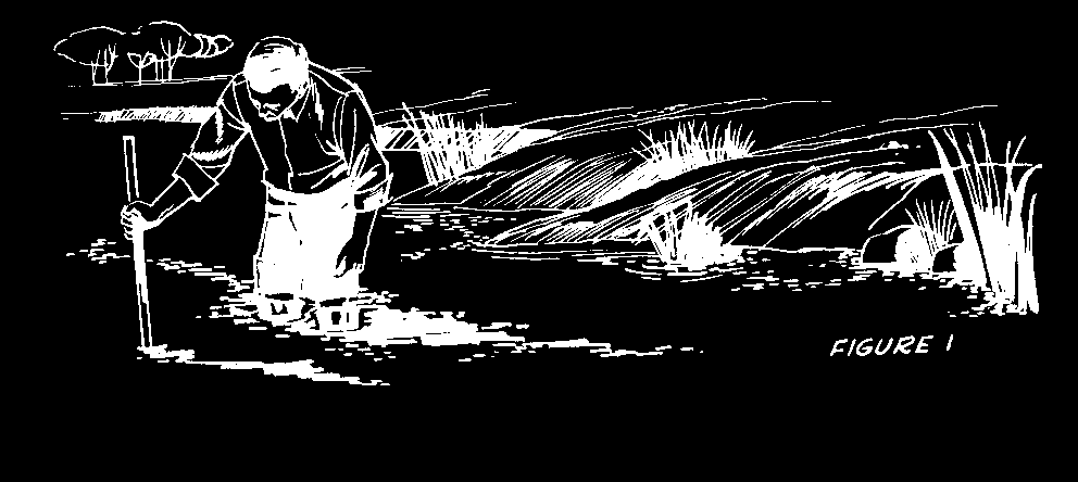
Stick for measuring depth
The following equation will help you to measure flow quickly:
Q = KxAxV,
where:
Q (Quantity) = flow in liters per minute
A (Area) = cross-section of stream, perpendicular to flow, in square meters
V (Velocity) = stream velocity, meters per minute
K (Constant) = a corrected conversion factor. This is used because surface flow is normally faster than average flow. For normal stages use K = 850; for flood states use ]K = 900 to 950.
To Find Area of a Cross-Section
The stream will probably have different depths along its length so select a place where the depth of the stream is average.
- Take a measuring stick and place it upright in the water about one-half meter (1 1/2') from the bank.
- Note the depth of water.
- Move the stick 1 meter (3') from the bank in a line directly across the stream. Note the depth.
o Move the stick 1.5 meters (4 1/2') from the bank, note the depth, and continue moving it at half-meter (1 1/2') intervals until you cross the stream.
Note the depth each time you place the stick upright in the stream. Draw a grid, like the one in Figure 2, and mark the varying depths on it so that a cross-section
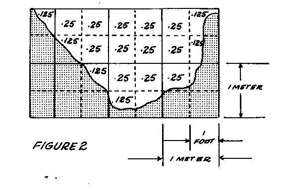
of the stream is shown. A scale of 1cm to 10cm is often used for such grids. By counting the grid squares and fractions of squares, the area of the water can be estimated. For example, the grid shown here has a little less than 4 square meters of water.
To Find Velocity
Put a float in the stream and measure the distance of travel in one minute (or fraction of a minute, if necessary.) The width of the stream where the velocity is being measured should be as constant as possible and free of rapids.
A light surface float, such as a chip, will often change course because of wind or surface currents. A weighted float, which sits upright in the water, will not change course so easily. A lightweight tube or tin can, partly filled with water or gravel so that it floats upright with only a small part showing above water, makes a good float for measuring.
Measuring Wide Streams
For a wide, irregular stream, it is better to divide the stream into 2- or 3-meter sections and measure the area and velocity of each. Q is then calculated for each section and the Qs added together to give a total flow.
Example (see Figure 2):
Cross section is 4 square meters
Velocity of float = 6 meters traveled in 1/2 minute
Stream flow is normal
Q = 850 x 4 x 6 meters -------- .5 minute
Q = 40,800 liters per minute or 680 liters per second
Using English Units
If English units of measurement are used, the equation for measuring stream flow is: Q = K x A x V, where:
Q = flow in U.S. gallons per minute
A = cross-section of stream, perpendicular to flow, in square feet
V = stream velocity in feet per minute
K = a corrected conversion factor: 6.4 for normal stages; 6.7 to 7.1 for flood stages
The grid used would be like the one in Figure 3; a common scale is 1" to 12".
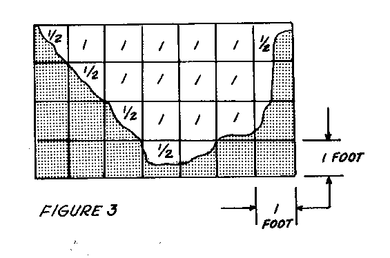
Example:
Cross-section is 15 square feet
Float velocity = 20' in 1/2 minute
Stream flow is normal
Q = 6.4 x 15 x 20 feet ------- .5 minute
Q = 3,800 gallons per minute
Source:
Clay, C.H. Design of Fishways and Other Fish Facilities. Ottawa: P.E. Department of Fisheries of Canada, 1961.
Measuring Water Flow in Partially-Filled Pipes
The flow of water in partially-filled horizontal pipes (Figure 1) or circular
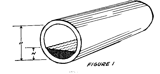
channels can be determined-if you know the inside diameter of the pipe and the depth of the water flowing-by using the alignment chart (nomograph) in Figure 2.
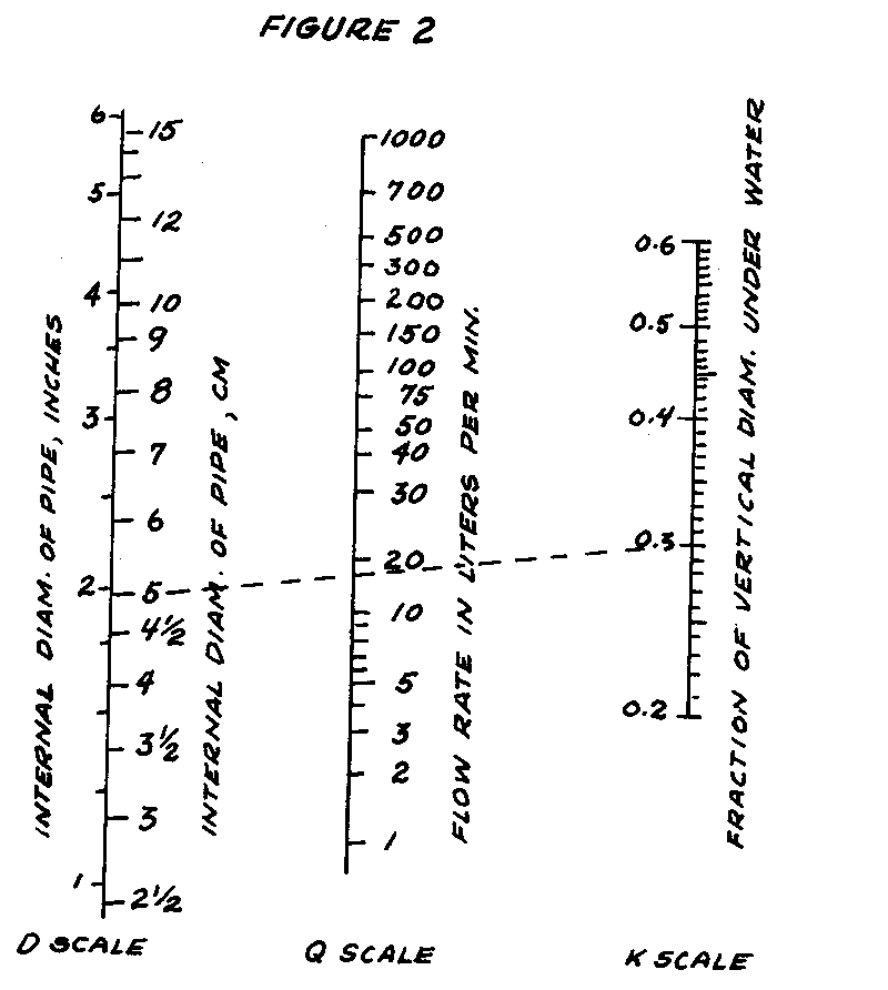
This method can be checked for low flow rates and small pipes by measuring the time required to fill a bucket or drum with a weighed quantity of water. A liter of water weighs 1kg (1 U.S. gallon of water weighs 8.33 pounds).
Tools and Materials
Ruler to measure water depth (if ruler units are inches, multiply by 2.54 to convert to centimeters) Straight edge, to use with alignment chart
The alignment chart applies to pipes with 2.5cm to 15cm inside diameters, 20 to 60% full of water, and having a reasonably smooth surface (iron, steel, or concrete sewer pipe). The pipe or channel must be reasonably horizontal if the result is to be accurate. The eye, aided by a plumb line to give a vertical reference, is a sufficiently good judge. If the pipe is not horizontal another method will have to be used. To use the alignment chart, simply connect the proper point on the "K" scale with the proper point on the "d" scale with the straight edge. The flow rate can then be read from the "q" scale.
q = rate of flow of water, liters per minute 8.33 pounds = 1 gallon.
d = internal diameter of pipe in centimeters.
K = decimal fraction of vertical diameter under water. Calculate K by measuring the depth of water (h) in the pipe and dividing it by the pipe diameter (d), or K = h (see Figure 1).

- d Example:
What is the rate of flow of water in a pipe with an internal diameter of 5cm, running 0.3 full? A straight line connecting 5 on the d-scale with 0.3 on the K-scale intersects the q-scale at flow of 18 liters per minute.
Source:
Greve Bulletin 32, Volume 12, No. 5, Purdue University, 1928.
Determining Probable Water Flow with Known Reservoir Height and Size and Length of Pipe
The alignment chart in Figure 1 gives a reasonably accurate determination of water flow when pipe size, pipe length, and height of the supply reservoir are known. The example given here is for the analysis of an existing system. To design a new system, assume a pipe diameter and solve for flow rate, repeating the procedure with new assumed diameters until one of them provides a suitable flow rate.
Tools and Materials
Straightedge, for use with alignment chart Surveying instruments, if available
The alignment chart was prepared for clean, new steel pipe. Pipes with rougher surfaces or steel or cast iron pipe that has been in service for a long time may give flows as low as 50 percent of those predicted by this chart.
The available head (h) is in meters and is taken as the difference in elevation between the supply reservoir and the point of demand. This may be crudely estimated by eye, but for accurate results some sort of surveying instruments are necessary.
For best results, the length of pipe (L) used should include the equivalent lengths of fittings as described in the section, "Estimating Flow Resistance of Pipe Fittings," p. 76. This length (L) divided by the pipe internal diameter (D) gives the necessary "L/D" ratio. In calculating L/D, note that the units of measuring both "L" and "D" must be the same, e.g., feet divided by feet; meters divided by meters; centimeters by centimeters.
Example:
Given available head (h) of 10 meters, pipe internal diameter (D) of 3cm, and equivalent pipe length (L) of 30 meters (3,000cm).
Calculate L/D = 3,000cm = 1,000 ------- 3cm
The alignment chart solution is in two steps:
- Connect internal diameter 3cm to available head (10 meters), and make a mark on the Index Scale. (In this step, disregard "Q" scale)
- Connect mark on Index Scale with L/D (1,000), and read flow rate (Q) of approximately 140 liters per minute.
Estimating Water Flow from Horizontal Pipes
If a horizontal pipe is discharging a full stream of water, you can estimate the rate of flow from the alignment chart in Figure 2. This is a standard engineering

technique for estimating flows; its results are usually accurate to within 10 percent of the actual flow rate.
Tools and Materials
Straightedge and pencil, to use alignment chart Tape measure Level Plumb bob
The water flowing from the pipe must completely fill the pipe opening (see Figure 1).

The results from the chart will be most accurate when there is no constricting or enlarging fitting at the end of the pipe.
Example:
Water is flowing out of a pipe with an inside diameter (d) of 3cm (see Figure 1). The stream drops 30cm at a point 60cm from the end of the pipe.
Connect the 3cm inside diameter point on the "d" scale in Figure 2 with the 60cm point on the "D" scale. This line intersects the "q" scale at about 100 liters per minute, the rate at which water is flowing out of the pipe.
Source:
Duckworth, Clifford C. "Flow of Water from Horizontal Open-end Pipes." Chemical Processing, June 1959, p. 73.
Determining Pipe Size or Velocity of Water in Pipes
The choice of pipe size is one of the first steps in designing a simple water system.
The alignment chart in Figure 1 can be used to compute the pipe size needed for

a water system when the water velocity is known. The chart can also be used to find out what water velocity is needed with a given pipe size to yield the required rate of flow.
Tools and Materials
Straightedge Pencil
Practical water systems use water velocities from 1.2 to 1.8 meters (3.9 to 5.9 feet) per second. Very fast velocity requires high pressure pumps, which in turn require large motors and use excessive power. Velocities that are too low are expensive because larger pipe diameters must be used.
It may be advisable to calculate the cost of two or more systems based on different pipe sizes. Remember, it is usually wise to choose a little larger pipe if higher flows are expected in the next 5 to 10 years. In addition, water pipes often build up rust and scale, reducing the diameter and thereby increasing the velocity and pump pressure required to maintain flow at the original rate. If extra capacity is designed into the piping system, more water can be delivered by adding to the pump capacity without changing all the piping.
To use the chart, locate the flow (liters per minute) you need on the Q-scale. Draw a line from that point, through 1.8m/sec velocity on the V-scale, to the d-scale. Choose the nearest standard size pipe.
For example, suppose you need a flow of 50 liters per minute at the time of peak demand. Draw a line from 50 liters per minute on the Q-scale through 1.8m/sec on the V-scale. Notice that this intersects the d-scale at about 2.25. The correct pipe size to choose would be the next largest standard pipe size, e.g., 1" nominal diameter, U.S. Schedule 40. If pumping costs (electricity or fuel) are high, it would be well to limit velocity to 1.2m/sec and install a slightly larger pipe size.
Source:
Crane Company Technical Paper #409, pages 46-47.
Estimating Flow Resistance of Pipe Fittings
One of the forces a pump must overcome to deliver water is the friction/resistance of pipe fittings and valves to the flow of water. Any bends, valves, constrictions, or enlargements (such as passing through a tank) add to friction.
The alignment chart in Figure 1 gives a simple but reliable way to estimate this resistance: it gives the equivalent length of straight pipe that would have the same resistance. The sum of these equivalent lengths is then added to the actual length of pipe. This gives the total equivalent pipe length, which is used in the entry, "Determining Pump Capacity and Horsepower Requirements," to determine total friction loss.
Rather than calculate the pressure drop for each valve or fitting separately, Figure 1 gives the equivalent length of straight pipe.
Valves
Note the difference in equivalent length depending on how far the valve is open.
- Gate Valve: full opening valve; can see through it when open; used for complete shut off of flow.
- Globe Valve: cannot see through it when open; used for regulating flow.
- Angle Valve: like the globe, used for regulating flow.
- Swing Check Valve: a flapper opens to allow flow in one direction but closes when water tries to flow in the opposite direction.
Example 1:
Pipe with 5cm inside diameter
Equivalent Length in Meters
a. Gate Valve (fully open) .4 b. Flow into line - ordinary entrance 1.0 c. Sudden enlargement into 10cm pipe 1.0 (d/D = 1/2) d. Pipe length 10.0
Total Equivalent Pipe Length 12.4
Example 2:
Pipe with 10cm inside diameter
Equivalent Length in Meters
a. Elbow (standard) 4.0 b. Pipe length 10.0
Total Equivalent Pipe Length 14.0
Fittings
Study the variety of tees and elbows: note carefully the direction of flow through the tee. To determine the equivalent length of a fitting, (a) pick proper dot on "fitting" line, (b) connect with inside diameter of pipe, then using a straight edge read equivalent length of straight pipe in meters, and (c) add the fitting equivalent length to the actual length of pipe being used.
Source:
Crane Company Technical Paper #409, pages 20-21.
Bamboo Piping
Where bamboo is readily available, it seems to be a good substitute for metal pipe. Bamboo pipe is easy to make with unskilled labor and local materials. The important features of the design and construction of a bamboo piping system are given here.
Bamboo pipe is extensively used in Indonesia to transport water to villages. In many rural areas of Taiwan, bamboo is commonly used in place of galvanized iron for deep wells up to a maximum depth of 150 meters (492'). Bamboos of 50mm (2") diameter are straightened by means of heat, and the inside nodes knocked out. The screen is made by punching holes in the bamboo and wrapping that section with a fibrous mat-like material from a palm tree, Chamaerops humilis. In fact, such fibrous screens are also used in many galvanized iron tube wells.
Bamboo piping can hold pressure up to two atmospheres (about 2.1kg per square centimeter or 30 pounds per square inch). It cannot, therefore, be used as pressure piping. It is most suitable in areas where the source of supply is higher than the area to be served and the flow is under gravity.
Figure 1 is a sketch of a bamboo pipe water supply system for a number of

villages. Figure 2 shows a public water fountain.

Health Aspects
If bamboo piping is to carry water for drinking purposes, the only preservative treatment recommended is boric acid: borax in a 1:1 ratio by weight. The recommended treatment is to immerse green bamboo completely in a solution of 95 percent water and 5 percent boric acid.
After a bamboo pipe is put into operation it gives an undesirable odor to the water. This, however, disappears after about three weeks. If chlorination is done before discharge to the pipe, a reservoir giving sufficient contact time for effective disinfection is required since bamboo pipe removes chlorine compounds and no residual chlorine will be maintained in the pipe. To avoid possible contamination by ground water, an ever present danger, it is desirable to maintain the pressure within the pipe at a higher level than any water pressure outside the pipe. Any leakage will then be from the pipe, and contaminated water will not enter the pipe.
Design and Construction
Tools and Materials
Chisels (see text and Figure 3)

Nail, cotter pin, or linchpin Caulking materials Tar Rope
Bamboo pipe is made of lengths of bamboo of the desired diameter by boring out the dividing membrane at the joints. A circular chisel for this purpose is shown in Figure 3. One end of a short length of steel pipe is belled out to increase the diameter and the edge sharpened. A length of bamboo pipe of sufficiently small diameter to slide into the pipe is used as a boring bar and secured to the pipe by drilling a small hole through the assembly and driving a nail through the hole. (A cotter pin or linchpin could be used instead of the nail.) Three or more chisels ranging from smallest to the maximum desired diameter are required. At each joint the membrane is removed by first boring a hole with the smallest diameter chisel, then progressively enlarging the hole with the larger diameter chisels.
Bamboo pipe lengths are joined in a number of ways, as shown in Figure 4. Joints

are made watertight by caulking with cotton wool mixed with tar, then tightly binding with rope soaked in hot tar.
Bamboo pipe is preserved by laying the pipe below ground level and ensuring a continuous flow in the pipe. Where the pipe is laid above ground level, it is protected by wrapping it with layers of palm fiber with soil between the layers. This treatment will give a life expectancy of about 3 to 4 years to the pipe; some bamboo will last up to 5-6 years. Deterioration and failure usually occur at the natural joints, which are the weakest parts.
Where the depth of the pipe below the water source is such that the maximum pressure will be exceeded, pressure relief chambers must be installed. A typical chamber is shown in Figure 5. These chambers are also installed as reservoirs for
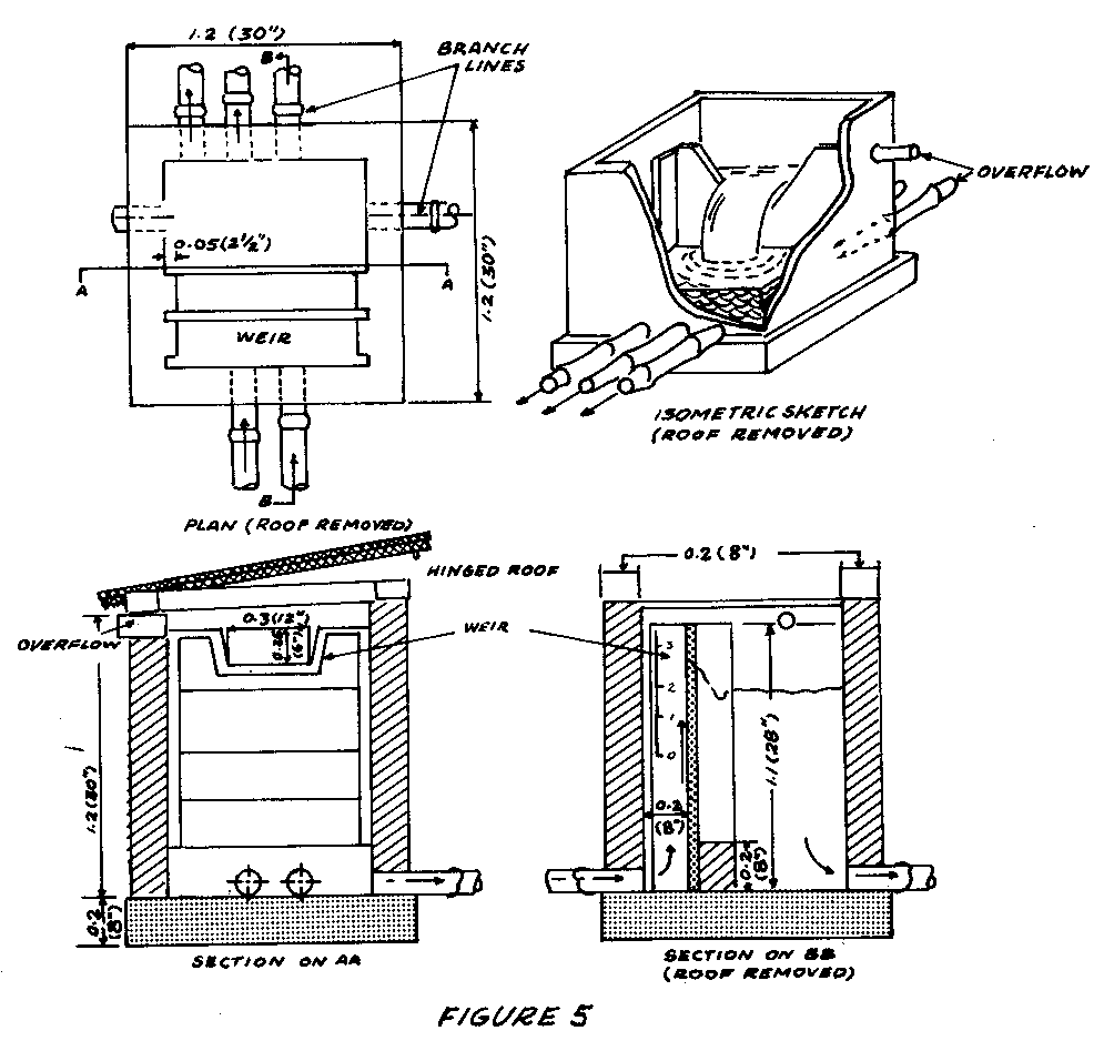
branch supply lines to villages en route.
Size requirements for bamboo pipe may be determined by using the pipe capacity alignment chart in Figure 6.
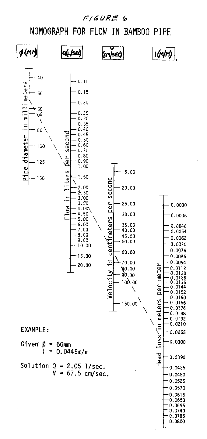
Source:
Water Supply Using Bamboo Pipe. AID-UNC/IPSED Series Item No. 3, International Program in Sanitary Engineering Design, University of North Carolina, 1966.
WATER LIFTING
Pump Specifications: Choosing or Evaluating a Pump
The form given in Figure 1, the "Pump Application Fact Sheet," is a check list
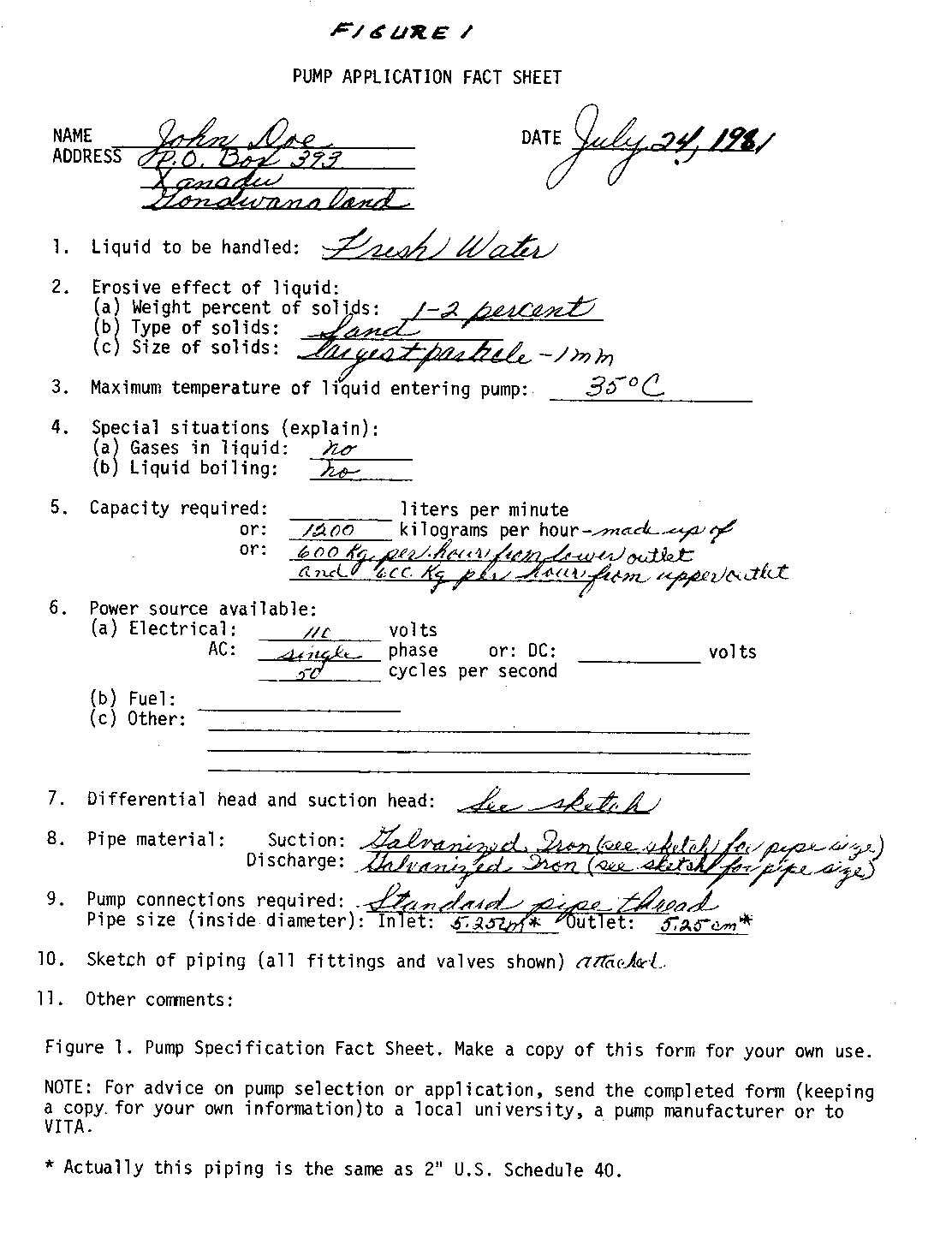
for collecting the information needed to get help in choosing a pump for a particular situation. If you have a pump on hand, you can also use the form to estimate its capabilities. The form is an adaptation of a standard pump specification sheet used by engineers.
Fill out the form and send it off to a manufacturer or a technical assistance organization like VITA to get help in choosing a pump. If you are doubtful about how much information to give, it is better to give too much information than to risk not giving enough. When seeking advice on how to solve a pumping problem or when asking pump manufacturers to specify the best pump for your service, give complete information on what its use will be and how it will be installed. If the experts are not given all the details, the pump chosen may give you trouble.
The "Pump Application Fact Sheet" is shown filled in for a typical situation. For your own use, make a copy of the form. The following comments on each numbered item on the fact sheet will help you to complete the form adequately.
- Give the exact composition of the liquid to be pumped: Fresh or salt water, oil, gasoline, acid, alkali, etc.
- Weight percent of solids can be found by getting a representative sample in a pail. Let the solids settle to the bottom and decant the liquid (or filter the liquid through a cloth so that the liquid coming through is clear). Weigh the solids and the liquid, and give the weight percent of solids.
If this is not possible, measure the volume of the sample (in liters, U.S. gallons, etc.) and the volume of solids (in cubic centimeters, teaspoons, etc.) and send these figures. Describe the solid material completely and send a small sample if possible. This is important; if the correct pump is not selected, the solids will erode and/or break moving parts.
Weight percent of solids =
100 x weight of solids in liquid sample --------------------------------------- weight of liquid sample
- If you do not have a thermometer to measure temperature, guess at it, making sure you guess on the high side. Pumping troubles are often caused when liquid temperatures at the intake are too high.
- Gas bubbles or boiling cause special problems, and must always be mentioned.
- Give the capacity (the rate at which you want to move the liquid) in any convenient units (liters per minute, U.S. gallons per minute) by giving the total of the maximum capacity needed for each outlet.
- Give complete details on the power source.
A. If you are buying an electric motor for the pump, be sure to give your voltage. If the power is A.C. (Alternating Current) give the frequency (in cycles per second) and the number of phases. Usually this will be single phase for most small motors. Do you want a pressure switch or other special means to start the motor automatically?
B. If you want to buy an engine driven pump, describe the type and cost of fuel, the altitude, maximum air temperature, and say whether the air is unusually wet or dusty.
C. If you already have an electric motor or engine, give as much information about it as you can. Give the speed and sketch the machine, being especially careful to show the power shaft diameter and where it is with respect to the mounting. Describe the size and type of pulley if you intend to use a belt drive. Finally, you must estimate the power. The best thing is to copy the name plate data completely. If possible give the number of cylinders in your engine, their size, and the stroke.
- The "head" or pressure to be overcome by the pump and the capacity (or required flow of water) determine the pump size and power. The entry "Determining Pump Capacity and Horsepower Requirements," explains the calculation of simple head situations. The best approach is to explain the heads by drawing an accurate piping sketch (see Item 10 in the "Pump Application Fact Sheet"). Be sure to give the suction lift and piping separately from the discharge lift and piping. An accurate description of the piping is essential for calculating the friction head. See Figure 2.
- The piping material, inside diameter, and thickness are necessary for making the head calculations and to check whether pipes are strong enough to withstand the pressure. See "Water Lifting and Transport-Overview" for comments on specifying pipe diameter.
- Connections to commercial pumps are normally flanged or threaded with standard pipe thread.
- In the sketch be sure to show the following:
(a) Pipe sizes; show where sizes are changed by indicating reducing fittings.
(b) All pipe fittings-elbows, tees, valves (show valve type), etc.
(c) Length of each pipe run in a given direction. Length of each size pipe and vertical lift are the most important dimensions.
- Give information on how the pipe will be used. Comment on such points as:
- Indoor or outdoor installation? + Continuous or intermittent service? + Space or weight limitations?
Source:
Benjamin P. Coe, VITA Volunteer, Schenectady, New York.
Determining Pump Capacity and Horsepower Requirements
With the alignment chart in Figure 1, you can determine the necessary pump size
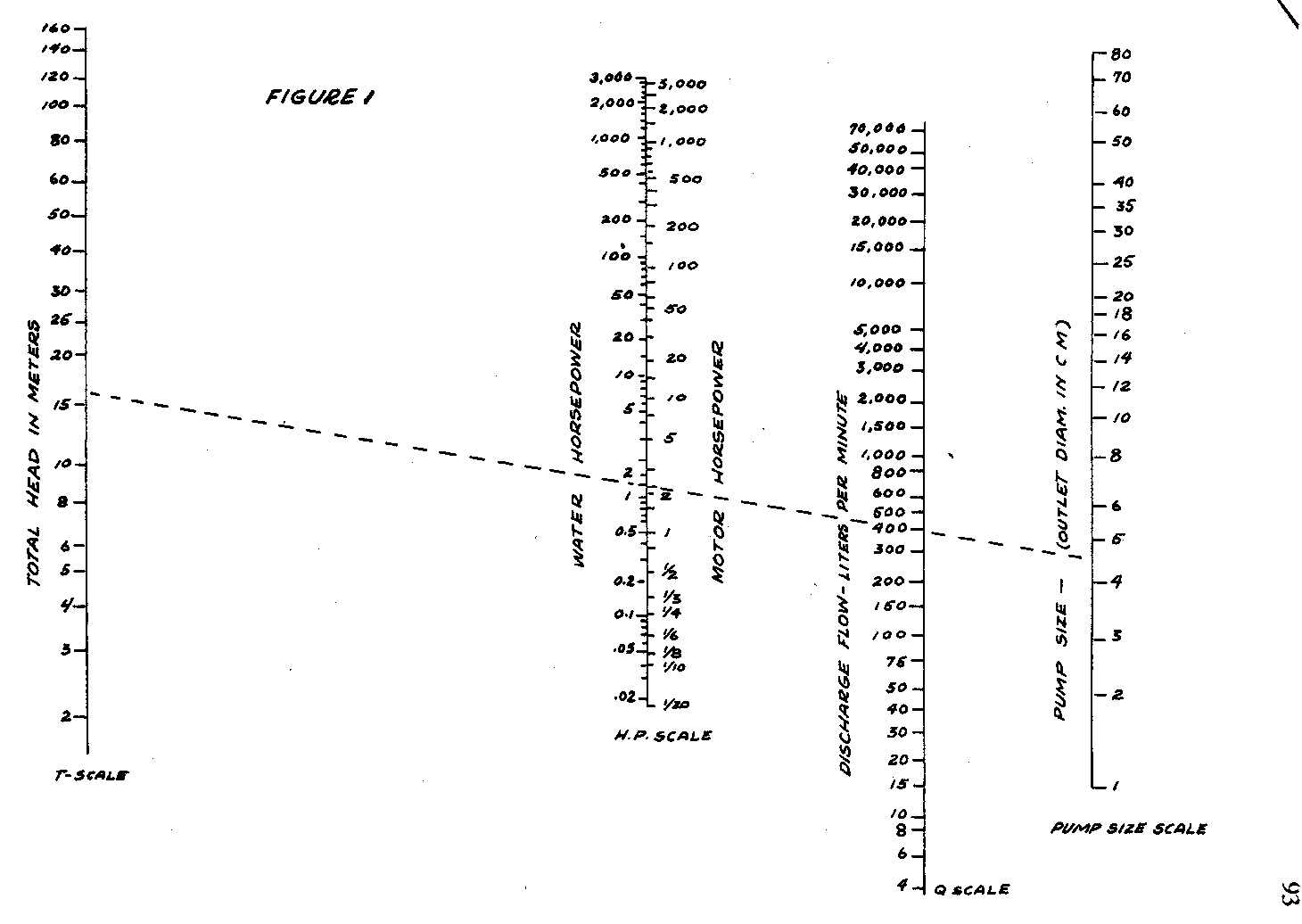
(diameter or discharge outlet) and the amount of horsepower needed to power the pump. The power can be supplied by people or by motors.
An average healthy person can generate about 0.1 horsepower (HP) for a reasonably long period and 0.4HP for short bursts. Motors are designed for varying amounts of horsepower.
To get the approximate pump size needed for lifting liquid to a known height through simple piping, follow these steps:
- Determine the quantity of flow desired in liters per minute.
- Measure the height of the lift required (from the point where the water enters the pump suction piping to where it discharges).
- Using the entry "Determining Pipe Size or Velocity of Water in Pipes," page 74, choose a pipe size that will give a water velocity of about 1.8 meters per second (6' per second). This velocity is chosen because it will generally give the most economical combination of pump and piping; Step 5 explains how to convert for higher or lower water velocities.
- Estimate the pipe friction-loss head (a 3-meter head represents the pressure at the bottom of a 2-meter-high column of water) for the total equivalent pipe length, including suction and discharge piping and equivalent pipe lengths for valves and fittings, using the following equation:
Friction-loss head = F x total equivalent pipe length -------------------------------- 100
where F equals approximate friction head (in meters) per 100 meters of pipe. To get the value of F, see the table below. For an explanation of total equivalent pipe length, see preceding sections.
- To find F (approximate friction head in meters per 100m of pipe) when water velocity is higher or lower than 1.8 meters per second, use the following equation:
F [V.sup.2] at 1.8/[sec.sup.x
F = 1.8/[sec.sup.2]
where V = higher or lower velocity
Example:
If the water velocity is 3.6m per second and F at 1.8m/sec is 16, then:
F = 16 x [3.6.sup.2] 16 x 13 ---------------- = ------- = 64 [1.8.sup.2] 3.24
- Obtain "Total Head" as follows:
Total Head = Height of Lift + Friction-loss Head
Average friction loss in meters for fresh water flowing through steel pipe velocity is 1.8 meters (6 feet) per second
Pipe inside diameter: cm 2.5 5.1 7.6 10.2 15.2 20.4 30.6 61.2 inches(*) 1" 2" 3" 4" 6" 8" 12" 24"
F (approximate friction 16 7 5 3 2 1.5 1 0.5 loss in meters per 100 meters of pipe)
(*) For the degree of accuracy of this method, either actual inside diameter in inches, or nominal pipe size, U.S. Schedule 40, can be used.
- Using a straightedge, connect the proper point on the T-scale with the proper point on the Q-scale; read motor horsepower and pump size on the other two scales.
Example:
Desired flow: 400 liters per minute Height of lift: 16 meters, No fittings Pipe size: 5cm Friction-loss head: about 1 meter Total head: 17 meters
Solution:
Pump size: 5cm Motor horsepower: 3HP
Note that water horsepower is less than motor horsepower (see HP-scale, Figure 1). This is because of friction losses in the pump and motor. The alignment chart should be used for rough estimate only. For an exact determination, give all information on flow and piping to a pump manufacturer or an independent expert. He has the exact data on pumps for various applications. Pump specifications can be tricky especially if suction piping is long and the suction lift is great.
For conversion to metric horsepower given the limits of accuracy of this method, metric horsepower can be considered roughly equal to the horsepower indicated by the alignment chart (Figure 1). Actual metric horsepower can be obtained by multiplying horsepower by 1.014.
Source:
Kulman, CA. Nomographic Charts. New York: McGraw-Hill Book Co., 1951.
Determining Lift Pump Capability
The height that a lift pump can raise water depends on altitude and, to a lesser extent, on water temperature. The graph in Figure 1 will help you to find out

what a lift pump can do at various altitudes and water temperatures. To use it, you will need a measuring tape and a thermometer.
If you know your altitude and the temperature of your water, Figure 1 will tell you the maximum allowable distance between the pump cylinder and the lowest water level expected. If the graph shows that lift pumps are marginal or will not work, then a force pump should be used. This involves putting the cylinder down in the well, close enough to the lowest expected water level to be certain of proper functioning.
The graph shows normal lifts. Maximum possible lifts under favorable conditions would be about 1.2 meters higher, but this would require slower pumping and would probably give much difficulty in "losing the prime."
Check predictions from the graph by measuring lifts in nearby wells or by experimentation.
Example:
Suppose your elevation is 2,000 meters and the water temperature is 25[degrees]C. The graph shows that the normal lift would be four meters.
Source:
Baumeister, Theodore. Mechanical Engineer's Handbook, 6th edition. New York: McGraw-Hill Book Co., 1958.
SIMPLE PUMPS
Chain Pump for Irrigation
The chain pump, which can be powered by hand or animal, is primarily a shallow-well pump to lift water for irrigation (see Figure 1). It works best when the lift
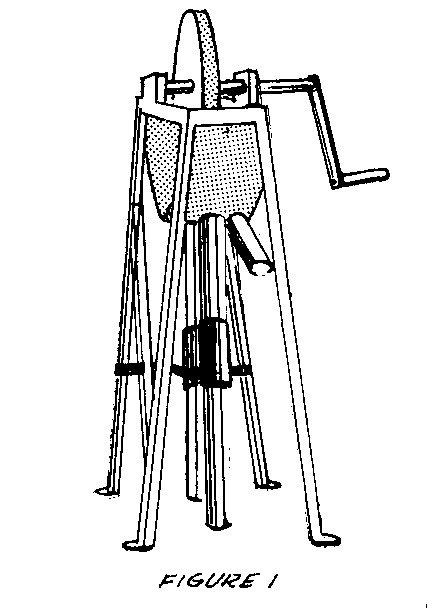
is less than 6 meters (20'). The water source must have a depth of about 5 chain links.
Both the pump capacity and the power requirement for any lift are proportional to the square of the diameter of the tube. Figure 2

shows what can be expected from a 10cm (4") diameter tube operated by four people working in two shifts.
The pump is intended for use as an irrigation pump because it is difficult to seal for use as a sanitary pump.
Tools and Materials
Welding or brazing equipment Metal-cutting equipment Woodworking tools Pipe: 10cm (4") outside diameter, length as needed 5cm (2") outside diameter, length as needed Chain with links about 8mm (5/16") in diameter, length as needed Sheet steel, 3mm (1/8") thick Sheet steel, 6mm (1/4") thick Steel rod, 8mm (5/16") in diameter Steel rod, 12.7mm (1/2") in diameter Leather or rubber for washers
The entire chain pump is shown in Figure 3. Details of this pump can be changed

to fit materials available and structure of the well.
The piston links (see Figures 4, 5, 6 and 7) are made from three parts:
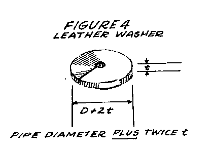
- a leather or rubber washer (see Figure 4) with an outside diameter about
two thicknesses of a washer larger than the inside diameter of the pipe.
- a piston disk (see Figure 5).
- a retaining plate (see Figure 6).
The piston link is made as shown in Figure 7. Center all three parts and clamp
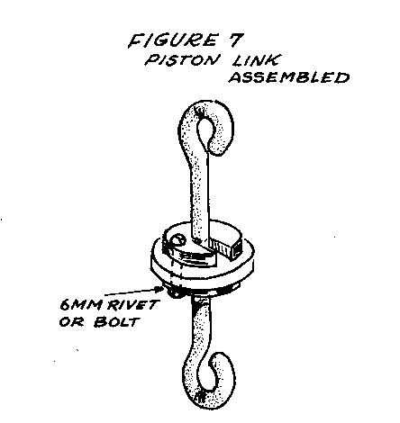
them together temporarily. Drill a hole about 6mm (1/4") in diameter through all three parts and fasten them together with a bolt or rivet.
The winch is built as shown in Figure 3. Two steel disks 6mm (1/4") thick are
welded to the pipe shaft.
Twelve steel rods, 12.7mm (1/2") thick, are spaced at equal distances, at or near the outside diameter, and are welded in place. The rods may be laid on the outside of the disks, if desired.
A crank and handle of wood or metal is then welded or bolted to the winch shaft.
The supports for the winch shaft (see Figure 3) can be V-notched to hold the shaft, which will gradually wear its own groove. A strap or block can be added across the top, if necessary, to hold the shaft in place.
The pipe can be supported by threading or welding a flange to its upper end (see Figure 8).

The flange should be 8mm to 10mm (5/16" to 3/8") thick. The pipe passes through a hole in the bottom of the trough and hangs from the trough into the well.
Sources:
Robert G. Young, VITA Volunteer, New Holland, Pennsylvania
Molenaar, Aldert. Water Lifting Devices for Irrigation. Rome: Food and Agriculture Organization, 1956.
Inertia Hand Pump
The inertia hand pump described here (Figure 1) is a
very efficient pump for lifting water short distances. It lifts water 4 meters (13') at the rate of 75 to 114 liters (20 to 30 U.S. gallons) per minute. It lifts water 1 meter (3.3') at the rate of 227 to 284 liters (60 to 75 gallons) per minute. Delivery depends on the number of persons pumping and their strength.
The pump is easily built by a tinsmith. Its three moving parts require almost no maintenance. The pump has been built in three different sizes for different water levels.
The pump is made from galvanized sheet metal of the heaviest weight obtainable that can be easily worked by a tinsmith (24- to 28-gauge sheets have been used successfully). The pipe is formed and made air tight by soldering all joints and seams. The valve is made from the metal of discarded barrels and a piece of truck inner tube rubber. The bracket for attaching the handle is also made from barrel metal.
Figure 1 shows the pump in operation. Figure 2 gives the
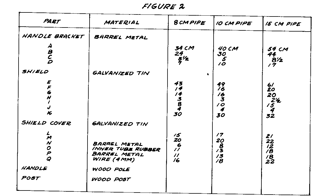
dimensions of parts for pumps in three sizes and Figure 3

shows the capacity of each size. Figures 4, 5, and 6 are
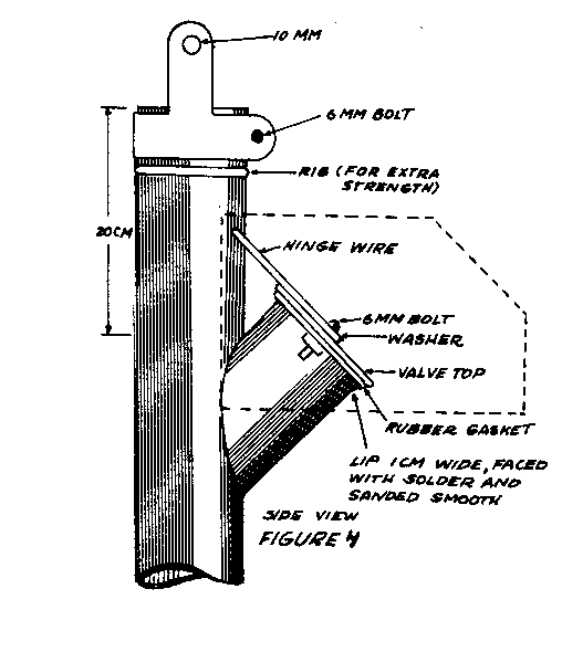
Tools and Materials (for 1-meter (3.3') pump)
Soldering equipment Drill and bits or punch Hammer, saws, tinsnips Anvil (railroad rail or iron pipe) Galvanized iron (24 to 28 gauge): Shield: 61cm x 32cm, 1 piece (24" x 12 5/8") Shield cover: 21cm x 22cm, 1 piece (8 1/4" x 8 5/8") Pipe: 140cm x 49cm, 1 piece (55 1/8" x 19 1/4") Top of pipe: 15cm x 15cm, 1 piece (6" x 6") "Y" pipe: 49cm x 30cm, 1 piece (19 1/4" x 12") Barrel metal: Bracket: 15cm x 45cm, 1 piece (6" x 21 1/4") Valve-bottom: 12cm (4 3/4") in diameter, 1 piece Valve-top: 18cm (7 1/8") in diameter, 1 piece Wire: Hinge: 4mm (5/32") in diameter, 32cm (12 5/8") long
This pump can also be made from plastic pipe or bamboo.
There are two points to be remembered concerning this pump. One is that the distance from the top of the pipe to the top of the hole where the short section of pipe is connected must be 20cm (8"). See Figure 4. The air that stays in the

pipe above this junction serves as a cushion (to prevent "hammering") and regulates the number of strokes pumped per minute. The second point is to remember to operate the pump with short strokes, 15 to 20cm (6" to 8"), and at a rate of about 80 strokes per minute. There is a definite speed at which the pump works best and the operators will soon get the "feel" of their own pumps.
In building the two larger size pumps it is sometimes necessary to strengthen the pipe to keep it from collapsing if it hits the side of the well. It can be strengthened by forming "ribs" about every 30cm (12") below the valve or banding with bands made from barrel metal and attached with 6mm (1/4") bolts.
The handle is attached to the pump and post with a bolt 10mm (3/8") in diameter, or a large nail or rod of similar size.
Source: Dale Fritz, VITA Volunteer, Schenectady, New York.
Handle Mechanism for Hand Pumps
The wearing parts of this durable handpump handle mechanism are wooden (see Figure 1).
They can be easily replaced by a village carpenter. This handle has been designed to replace pump handle mechanisms which are difficult to maintain. Some have been in use for several years in India with only simple, infrequent repairs.
The mechanism shown in Figure 1 is bolted to the top flange of your pump. The mounting holes A and C in the block should be spaced to fit your pump (see Figure 6).
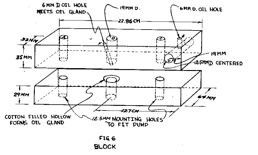
Figure 2 shows a pump with this handle mechanism that is manufactured

by F. Humane and Bros., 28 Strand Road, Calcutta, India.
Tools and Materials
Saw Drill Bits Tap: 12.5mm (1/2") Tap: 10mm (3/8") Chisel Drawknife, spokeshave or lathe Hardwoods 86.4cm x 6.4cm x 6.4cm (34" x 2 1/2" x 2 1/2") Mild steel rod: 10mm (3/4") in diameter and 46.5cm (16") long Strap iron, 2 pieces: 26.7cm x 38mm x 6mm (10 1/2" x 1 1/2" x 1/4")
BOLT HARDWARE
Number Number Number Number of bolts Dia. Length of nuts of lock- of plain Purpose- needed mm mm needed washers washers fastens:
1 10 38 0 0 0 76mm bolt to rod 1 10 76 0 0 2 Rod to handle 2 12.5 89 2 4 4 Link to handle Link to block 2 12.5 ? 2 2 2 Block to pump 1 12.5 ? 1 1 0 Rod to piston
Handle
Make the handle of tough hardwood, shaped on a lathe or by hand shaving. The slot should be cut wide enough to accommodate the rod with two plain washers on either side. See Figure 3.
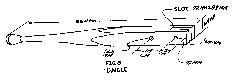
Rod
The rod is made of mild steel as shown in Figure 4. A 10mm (3/8")
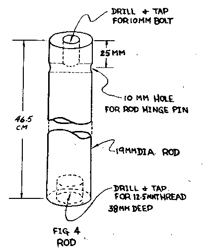
diameter machine bolt 38mm (1 1/2") long screws into the end of the rod to lock the rod hinge pin in place. The rod hinge pin is a 10mm (3/8") diameter machine bolt that connects the rod to the handle (see Figure 1). The end of the rod
can be bolted directly to the pump piston with a 12.5mm bolt. If the pump cylinder is too far down for this, a threaded 12.5mm (1/2") rod should be used instead.
Links
The links are two pieces of flat steel strap iron. Clamp them together for drilling to make the hole spacing equal. See Figure 5.
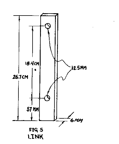
Block
The block forms the base of the lever mechanism, serves as a lubricated guide hole for the rod, and provides a means for fastening the mechanism to the pump barrel. If the block is accurately made of seasoned tough hardwood without knots, the mechanism will function well for many years. Carefully square the block to 22.9cm x 6.4cm x 6.4cm (9" x 1 1/2" x 1 1/2"). Next holes, A, B, C, and D are drilled perpendicular to the block as shown in Figure 6. The spacing of the
mounting holes A and C from hole B is determined by the spacing of the bolt holes in the barrel flange of your pump. Next saw the block in half in a plane 3.5cm (13/8") down from the top side. Enlarge hole B at the top of the lower section with a chisel to form an oil well around the rod. This well is filled with cotton. A 6mm (1/4") hole, F, is drilled at an angle from the oil well to the surface of the block. A second oil duct hole E is drilled in the upper section of the block to meet hole D. Use lockwashers under the head and nut of the link bolts to lock the bolts and links together. Use plain washers between the links and the wooden parts.
Source:
Abbott, Dr. Edwin. A Pump Designed for Village Use. Philadelphia: American Friends Service Committee, 1955.
Hydraulic Ram
A hydraulic ram is a self-powered pump that uses the energy of falling water to lift some of the water to a level above the original source. This entry explains the use of commercial hydraulic rams, which are available in some countries. Plans for building your own hydraulic ram are also available from VITA and elsewhere.
Use of the Hydraulic Ram
A hydraulic ram can be used wherever a spring or stream of water flows with at least a 91.5cm (3') fall in altitude. The source must be a flow of at least 11.4 liters (3 gallons) a minute. Water can be lifted about 7.6 meters (25') for each 30.5cm (12") of fall in altitude. It can be lifted as high as 152 meters (500'), but a more common lift is 45 meters (150').
The pumping cycle (see Figure 1) is:
- Water flows through the drive pipe (D) and out the outside valve (F).
- The drag of the moving water closes the valve (F).
- The momentum of water in the drive pipe (D) drives some water into the air chamber (A) and out the delivery pipe (I).
- The flow stops.
- The check valve (B) closes
- The outside valve (F) opens to start the next cycle.
This cycle is repeated 25 to 100 times a minute; the frequency is regulated by moving the adjustment weight (C).
The length of the drive pipe must be between five and ten times the length of the fall (see Figure 2). If the distance from the source to the ram is greater than

ten times the length of the fall, the length of the drive pipe can be adjusted by installing a stand pipe between the source and the ram (see B in Figure 2).
Once the ram is installed there is little need for maintenance and no need for skilled labor. The cost of a hydraulic ram system must include the cost of the pipe and installation as well as the ram. Although the cost may seem high, it must be remembered that there is no further power cost and a ram will last for 30 years or more. A ram used in freezing climates must be insulated.
A double-acting ram will use an impure water supply to pump two-thirds of the pure water from a spring or similar source. A third of the pure water mixes with the impure water. A supplier should be consulted for this special application.
To calculate the approximate pumping rate, use the following equation:
Capacity (gallons per hour) = V x F x 40 ---------- E
V = gallons per minute from source F = fall in feet E = height the water is to be raised in feet
Data Needed for Ordering a Hydraulic Ram
- Quantity of water available at the source of supply in liters (or gallons) per minute
- Vertical fall in meters (or feet) from supply to ram
- Height to which the water must be raised above the ram
- Quantity of water required per day
- Distance from the source of supply to the ram
- Distance from the ram to the storage tank
Sources:
Loren G. Sadler, New Holland, Pennsylvania
Rife Hydraulic Engine Manufacturing Company, Millburn, New Jersey
Sheldon, W.H. The Hydraulic Ram. Extension Bulletin 171, July 1943, Michigan State College of Agriculture and Applied Science.
"Country Workshop." Australian Country. September 1961, pages 32-33.
"Hydraulic Ram Forces Water to Pump Itself." Popular Science, October 1948, pages 231-233.
"Hydraulic Ram." The Home Craftsman, March-April 1963, pages 20-22.
RECIPROCATING WIRE POWER TRANSMISSION FOR WATER PUMP
A reciprocating wire can transmit power from a water wheel to a point up to 0.8km (1/2 mile) away where it is usually used to pump well water. These devices have been used for many years by the Amish people of Pennsylvania. If they are properly installed, they give long, trouble-free service.
The Amish people use this method to transmit <see figure 1> mechanical power from small water
wheels to the barnyard, where the reciprocating motion is used to pump well water for home and farm use. The water wheel is typically a small undershot wheel (with the water flowing under the wheel) one or two feet in diameter. The wheel shaft is fitted with a crank, which is attached to a triangular frame that pivots on a pole (see Figure 2). A wire is used to connect this frame to another
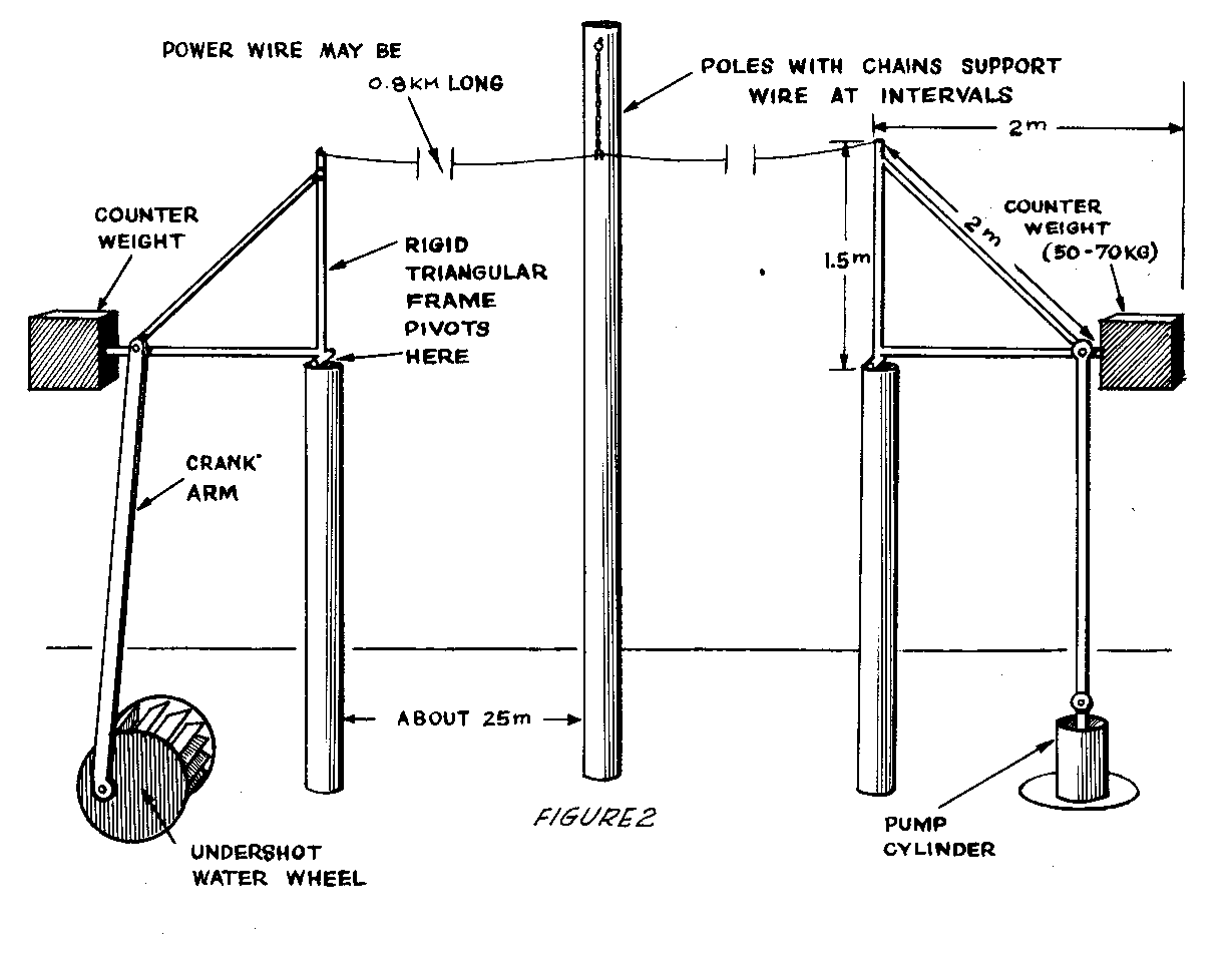
identical unit located over the well. Counterweights keep the wire tight.
Tools and Materials
Wire: galvanized smooth fence wire Water wheel with eccentric crank to give a motion slightly less than largest stroke of farmyard pump Galvanized pipe for triangle frames: 2cm (3/4") by 10 meters long (32.8') Welding or brazing equipment to make frames Concrete for counterweight 2 Poles: 12 to 25cm (6" to 10") in diameter.
As the water wheel turns, the crank tips the triangular frame back and forth. This action pulls the wire back and forth. One typical complete back and forth cycle takes 3 to 4 seconds. Sometimes power for several transmission wires comes from one larger water wheel.
The wire is mounted up on poles to keep it overhead and out of the way. If the distance from stream to courtyard is far, extra poles will be needed to help support the wire. Amish folks use a loop of wire covered with a small piece of garden hose attached to the top of the pole. The reciprocating wire slides back and forth through this loop. If this is not possible, try making the pole 1-2 meters higher than the power wire. Drive a heavy nail near the pole top and attach a chain or wire from it to the power wire as shown in Figure 3.
Turns can be made in order to follow hedgerows by mounting a small triangular frame horizontally at the top of a pole as shown in Figure 4.

Figures 5, 6, and 7 show how to
wheel made from wood and bamboo.
Source
New Holland, Pennsylvania VITA Chapter. References
REFERENCES
WATER RESOURCES
American Water Works Association. "AWWA Standard D-100-79 for Welded Steel Water Storage Tanks." Denver, Colorado: American Water Works Association, 1979.
American Water Works Association. "AWWA Standard D-105-80 for Disinfection of Water Storage Facilities." Denver, Colorado: American Water Works Association, 1980.
American Water Works Association. Water Distribution Operator Training Handbook. Denver, Colorado: American Water Works Association, 1976.
Anchor, R.D. Design of Liquid-Retaining Concrete Structures. New York: Wiley and Sons, 1982.
Blackwell, F.O., Farding, P.S., and Hilbert, M.S. Understanding Water Supply and Treatment for Individual and Small Community Systems. Arlington, Virginia: Volunteers in Technical Assistance, 1985.
Brown, J.H. "Flexible Membrane: An Economical Reservoir Liner and Cover." Journal of the American Water Works Association. Vol. 71, No. 6, June 1979.
Cairncross, S., and Feachem, R. Small Water Supplies. London: Ross Institute, 1978.
Crouch, Margaret (ed.). Six Simple Pumps. Arlington, Virginia: Volunteers in Technical Assistance, 1983.
Helweg, O.J., and Smith, G. "Appropriate Technology for Artificial Aquifers," Ground Water. Vol. 18, No. 3, May-June 1978.
Maddocks, D. Methods of Creating Low Cost Waterproof Membranes for Use in the Construction of Rainwater Catchment and Storage Systems. London: Intermediate Technology Publications, Ltd., 1975
Mazariegos, J. F., and de Zeissig, Julia A. A. Water Purification Using Small Artisan Filters. Guatemala: Central American Research Institute for Industry, 1981.
McJunkin, F. and Pineo, C. U.S. Agency for International Development. Water Supply and Sanitation in Developing Countries. Washington, D.C.: USAID, 1976.
Pacey, Arnold, and Cullis, Adrian. Rainwater Harvesting: The Collection of Rainfall and Runoff in Rural Areas. London: Intermediate Technology Publications, Ltd., 1996.
Remmers, J. Understanding Water Supply. General Considerations. Arlington, Virginia: Volunteers in Technical Assistance. 1985.
Ritter, C.M. Understanding Potable Water Storage. Arlington, Virginia: Volunteers in Technical Assistance (VITA), 1985.
Ryden, D.E. "Evaluating the Safety and Seismic Stability of Embankment Reservoirs." Journal of the American Water Works Association. Vol. 76, No. 1. Denver, Colorado: American Water Works Association, January 1984.
Salvato, JA., Jr. Environmental Engineering and Sanitation. New York: Wiley-Interscience, 1972.
Schiller, E.J., and Droste, R.L., eds. Water Supply and Sanitation in Developing Countries. Ann Arbor, Michigan: Ann Arbor Science Publishers, 1982
Sharma, P.N., and Helweg, OJ. "Optimum Design of Small Reservoir Systems." Journal of Irrigation and Drainage Division--American Society of Civil Engineers. Vol. 108, IR4, December 1982.
Sherer, K, "Technical Training of Peace Corps Volunteers in Rural Water Supply systems in Morocco." Water and Sanitation for Health Project (WASH) Field Report No. 43. Washington, D.C.: U.S. Agency for International Development, May 1982.
Silverman, G.S.; Nagy, LA.; and Olson, B.H. "Variations in Particulate Matter, Algae, and Bacteria in An Uncovered, Finished Drinking-Water Reservoir." Journal of the American Water Works Association. Vol. 75, No. 4. Denver, Colorado: American Water Works Association, April 1983.
Spangler, C.D. United Nations and World Bank. Low-Cost Water Distribution: A Field Manual. Washington, D.C.: World Bank, December 1980.
Swiss Association for Technical Assistance, ed. Manual for Rural Water Supply. Zurich, Switzerland: Swiss Center for Appropriate Technology, 1980.
Sylvestre, Emilio. "Water, Water Everywhere: Island Communities Install Water Systems." VITA News, October 1986, pp. 8-10.
United Nations. World Health Organization. "WHO Guidelines for Drinking Water Quality," by H.G. Gorchev and G. Ozolins. Geneva, Switzerland: World Health Organization, 1982.
United Nations. World Health Organization. "The Purification of Water on a Small Scale. WHO Technical paper No. 3. The Hague, The Netherlands: WHO International Reference Centre for Community Water Supply, March 1973.
United Nations. World Health Organization. "Preliminary List of References on Slow Sand Filtration and Related Simple pretreatment Methods." The Hague, The Netherlands: WHO International Reference Centre for Community Water Supply, July 1976.
Upmeyer, D.W. "Estimating Water Storage Requirements." Public Works. Vol. 109, No. 7, July 1978.
U.S. Environmental Protection Agency. Manual of Individual Water Supply Systems. Washington, D.C.: EPA, 1975.
"Wind Power for Roatan Island: Pumping Water in Honduras." VITA News, October 1982, pp. 3-7.
HEALTH AND SANITATION
American Concrete Institute. "Concrete Sanitary Engineering Structures." Report No. ACI 350R-83. Detriot, Michigan: American Concrete Institute, 1983.
Baumann, Werner, and Karpe, Hans Jurgen. Wastewater Treatment and Excreta Disposal in Developing Countries. West Germany: German Appropriate Technology Report, 1980.
Bull, David. A Growing Problem: Pesticides and the Third World Poor. Oxford: OXFAM, 1982.
Canter, L.W. and Malina, J.F. Sewege Treatment in Developing Countries. Norman, Oklahoma: The University of Oklahoma (under contract to USAID), December 1976.
Cointreau, Sandra J. Environmental Management or Urban Solid Wastes in Developing Countries (A Project Guide). Washington, D.C.: World Bank, June 1982.
Davis, B.P. Understanding Sanitation at the Community Level. Arlington, Virginia: Volunteers in Technical Assistance, 1985.
Feachem, Richard G.; Bradley, David; Garelick, Hemda; and Mara, D. Duncan. "Health Aspects of Excreta and Sullage Management: A State-of-the-Art Review." (Appropriate Technology for Water Supply and Sanitation, vol. 3). Washington, D.C.: World Bank, 1980.
Feachem, Richard, et al. Water, Health and Development: An Inter-disciplinary Evaluation. London: Tri-Med Books, Ltd., 1977. Feachem, Richard, McGarry, Michael, and Mara, D. Duncan (eds). Water, Wastes and Health in Hot Climates. New York: John Wiley and Sons, 1980.
Goldstein, Steven N., and Moberg, Walter J., Jr. Wastewater Treatment Systems for Rural Communities. Washington, D.C.: Commission on Rural Water, 1973.
Golveke, C.G. Biological Reclamation of Solid Wastes. Emmaus, Pennsylvania: Rodale Press, 1977.
Grover, Brian. Water Supply and Sanitation Project Preparation Handbook (vol. 1, Guidelines). Washington, D.C.: World Bank, 1982.
Herrington, J.E. Understanding Primary Health Care for a Rural Population. Arlington, Virginia: Volunteers in Technical Assistance, 1985.
Kalbermatten, John M., et al. "A Planner's Guide." (Appropriate Technology for Water Supply and Sanitation, vol. 2). Washington, D.C.: World Bank. 1981.
Kalbermatten, John M.; Julius, De Anne S.; and Gunnerson, Charles G. Appropriate Sanitation Alternatives. A technical and Economic Appraisal. Baltimore, Maryland: Johns Hopkins University Press (for the World Bank), 1982.
Mann, H.T., and Williamson, D. Water Treatment and Sanitation: Simple Methods for Rural Areas. London. Intermediate Technology Publications, 1982.
Patel, Ishwarbhai. Safai-Marg Darshika (A Guide Book on Sanitation). New Delhi: Udyogshala Press, 1970.
Reid, George and Coffey, Kay. (eds.). Appropriate Methods of Treating Water and Wastewater in Developing Countries. Norman, Oklahoma: Bureau of Water and Environmental Resources Research (University of Oklahoma), 1978.
Rybczynski, Witold, Polprasert, Changrak, and McGarry, Michael. Low-Cost Technology Options for Sanitation (A State-of-the-Art Review and Annotated Bibliography). Ottawa: International Development Research Centre, 1978.
Salvato, J.A., Jr. Environmental Engineering and Sanitation. New York: Wiley-Interscience, 1972.
Sanitation in Developing Countries (Proceedings of a workshop on training held in Lobatse, Botswana, 14-20 August 1980). Ottawa: International Development Research Centre, 1981.
Stonerook, H. Understanding Sewage Treatment and Disposal. Arlington, Virginia: Volunteers in Technical Assistance, 1994.
Strauss, Martin. Sanitation Handbook (Community Water Supply and Sanitation, Nepal). Pokhara, Nepal: Pokhara Centre Press, June 1982.
van Wijk-Sijbesma, Christine. Participation and Education in Community Water Supply and Sanitation Programmes - A Literature Review. The Hague: WHO International Reference Centre for Community Water Supply, 1979.
Vogler, Jon. Work from Waste. Recycling Wastes to Create Employment. Oxford: Intermediate Technology Publications Ltd. and OXFAM, 1981.
Werner, D. Where There Is No Doctor. A Village Health Care Handbook. Palo Alto, California: Hesperian Foundation, 1980.
AGRICULTURE
Abrahams, P.J. Understanding Soil Preparation. Arlington, Virginia: Volunteers in Technical Assistance, 1994
Archer, Sellers G. Soil Conservation. Norman, Oklahoma: University of Oklahoma Press, 1969.
Attfield, Harlan. Gardening With the Seasons. Arlington, Virginia: Volunteers in Technical Assistance, 1979.
Bartholomew, W.V. Soil Nitrogen--Supply Processes and Crop Requirements. Technical Bullentin 6. Raleigh, North Carolina: North Carolina State University, 1972.
Bird, H.R. Understanding Poultry Meat and Egg Production. Arlington, Virginia: Volunteers in Technical Assistance, 1984.
Bradenburg, N.R. Bibliography of Harvesting and Processing Forage Seed, 1949-1964. U.S. Department of Agriculture, Agricultural Research Service, ARS 42-135, Washington: USDA, 1968.
Branch, Diana S. (ed.). Tools for Homesteaders, Gardeners, and Small-Scale Farmers, Emmaus, Pennsylvania, 1978.
Corven, James. Basic Soil Improvement for Everyone. Arlington, Virginia: Volunteers in Technical Assistance, 1983.
Ensminger, M.E., and Olentine, C.G., Jr. Feeds and Nutrition. Clovis, California: Ensminger Publishing Co., 1978.
Fitts, J.W., and Fitts, J.B. Understanding Composting. Arlington, Virginia: Volunteers in Technical Assistance, 1984
Freeman, John A. Survival Gardening: Enough Nutrition from 1,000 Square Feet To Live On...Just in Case! Rock Hill, South Carolina: John's Press, 1983.
Hughes, H.D. Forages. Ames, Iowa: Iowa State University Press, 1966.
Hunt, Marjorie, and Bartz, Brenda. High Yield Gardening. Emmaus, Pennsylvania: Rodale Press, Inc., 1986.
National Academy of Sciences. Nutrient Requirements of Poultry. Washington, D.C.: National Academy Press, 1977.
North, M.O. Commercial Chicken Production Manual. Second Edition. Westport, Connecticut: AVI Publishing Co., Inc., 1978.
Orr, H.L. Duck and Goose Raising. Publication 532. Ontario, Canada: Ministry of Agriculture and Food.
Piliang, W.G.; Bird, H.R.; Sunde, M.L.; and Pringle, D.J. "Rice Bran as the Major Energy Source for Laying Hens." Poultry Science. 61 (1982): 357.
Reddy, K.R.; Khaleel, R.; and Overcash, M.R. "Behavior and Transport of Microbial Pathogens and Indicator Organisms in Soils Treated with Organic Wastes." Journal of Environmental Quality. Madison, Wisconsin: American Society of Agronomy, 1981.
Rodale, J., ed. The Complete Book of Composting. Emmaus, Pennsylvania: Rodale Press, Inc., 1969.
Russel, F. W. Soil Conditions and Plant Growth. London, England: Logmans Green and Co., Ltd., 1961.
Stern, Peter. Small Scale Irrigation. London: Intermediate Technology Publications, 1979.
Young, J.A., Evans, R.A. & Budy, J.D. Understanding Seed Collection and Handling. Arlington, Virginia: Volunteers in Technical Assistance, 1986.
FOOD PROCESSING AND PRESERVATION
Anderson, Jean. The Green Thumb Preserving Guide. New York: William Marrow & Company, Inc., 1976.
Barbour, Beverly. The Complete Food Preservation Book: New York: David McKay Company, Inc., 1978.
Burch, Joan, and Burch, Monte. Home Canning and Preserving. Reston, Virginia: Reston Publishing Company, Inc., 1977.
Carruthers, R.T. Understanding Fish Preservation and Processing. Arlington, Virginia: Volunteers in Technical Assistance, 1995.
Central Food Technological Research Institute. "Home-Scale Processing and Preservation of Fruits and Vegetables." Mysore, India: The Wesley Press, 1981.
Etchells, John L., and Jones, Ivan D. "Preservation of Vegetables by Salting or Brining," Farmers' Bulletin No. 1932. Washington, D.C.: U.S. Department of Agriculture, 1944.
Groppe, Christine C., and York, George K. "Pickles, Relishes, and Chutneys: Quick, Easy, and Safe Recipes." Leaflet No. 2275. Berkeley, California: University of California, Division of Agricultural Sciences, 1975.
Hertzberg, Ruth; Vaughan, Beatrice; and Greene, Janet. Putting Food By. Brattleboro, Vermont: The Stephen Greene Press.
Islam, Meherunnesa. Food Preservation in Bangladesh. Dacca, Bangladesh: Women's Development Programme, UNICEF/DACCA, 1977.
Kluger, Marilyn. Preserving Summer's Bounty. New York: M. Evans and Company, Inc., 1978.
Levinson, Leonard Louis. The Complete Book of Pickles and Relishes. New York: Hawthorn Books, Inc., 1965.
Lindblad, Carl, and Druben, Laurel. Small Farm Grain Storage. Arlington, Virginia: Volunteers in Technical Assistance, 1976.
Murry, Sue T. Home Curing Fish. Washington, D.C.: Agriculture and Rural Development Service, Agency for International Development, 1967.
Schuler, Stanley, and Schuler, Elizabeth Meriwether, Preserving the Fruits of the Earth. New York: The Dial Press, 1973.
Stiebeling, Jazel K. "Solar Food Preservation." Chicago, Illinois: Illinois Institute of Technology, 1981.
Stoner, Carol Hupping, Editor. Stocking Up: How To Preserve the Foods You Grow, Naturally. Emmaus, Pennsylvania: Rodale Press, 1977.
U.S. Department of Agriculture. Human Nutrition Research Division. "Home Canning of Fruits and Vegetables." Washington, D.C.: U.S. Department of Agriculture, 1965.
Weber, Fred, with Stoney, Carol. Reforestation in Arid Lands. Arlington, Virginia: Volunteers in Technical Assistance, 1986.
Worgan, J.T. "Canning and Bottling as Methods of Food Preservation in Developing Countries." Appropriate Technology. 4 (November 1977): 15-16.
CONSTRUCTION
Action Peace Corps. Handbook for Building Homes of Earth. Washington, D.C.: Department of Housing and urban Develop ment, (undated).
Ahrens, C. Manual for Supervising Self-Help Home Construction with Stabilized Earth Blocks Made in the CINVA-Ram Machine. Kanawha County, West Virginia, 1965.
American Concrete Institute. Handbook of Concrete Engineering. ACI-82 Manual of Practice. Detroit, Michigan: American Concrete Institute, 1982.
Buchanan, W. Hand Moulded Burnt Clay Bricks: Labour Intensive Production. Malawi Ministry of Trade, Industry, and Tourism (United Nations Industrial Development Organization, Project DP/MLW/78/003), undated.
Building with Adobe and Stabilized Earth Blocks. Washington, D.C.: United States Department of Agriculture, 1972.
Bush, Alfred. Understanding Stabilized Earth Construction. Arlington, Virginia: Volunteers in Technical Assistance, 1994.
Groben, E. W. Adobe Architecture: Its Design and Construction. Seattle, Washington: The Shorey Book Store, 1975.
International Institute of Housing Technology. The Manufacturing of Asphalt Emulsion Stabilized Soil Bricks and Brick Maker's Manual. Fresno, California: California State University, 1972.
Lunt, M.G. Stabilized Soil Blocks for Building. Garston, Watford, England: Building Research Establishment, 1980.
_________. "Stabilized Soil Blocks for Building." Overseas Building Notes No. 184. Garston, England: Building Research Establishment, February 1980.
Making Building Blocks with the CINVA-Ram Block Press. Arlington, Virginia: Volunteers in Technical Assistance, 1975.
Metalibec Ltd. CINVA-Ram Block Cement Soil in Large Scale Housing Construction in East Punjab. Bombay, India: Government of India Press, 1948.
Methods for Characterizing Adobe Building Materials. Washington, D.C.: National Bureau of Standards, 1978.
Parry, J.P. Brickmaking in Developing Countries. Prepared for Overseas Division, Building Research Establishment, UK Garston, Watford, United Kingdom: Building Research Establishment, 1979.
Salvadorean Foundation for Development and Low Cost Housing Research Unit. Stabilized Adobe. Washington, D.C.: Organization of American States, (undated)
Sidibe, B. Understanding Adobe. Arlington, Virginia: Volunteers in Technical Assistance (VITA), 1985.
U.S. Agency for International Development. Handbook for Building Homes of Earth. Action Pamphlet No. 4200.36. By Lyle A. Wolfskill, Wayne A. Dunlop, and Bob M. Callaway. Washington, D.C.: Peace Corps, December 1979.
U.S. Dept of the Army. Concrete, Masonry and Brickwork: A Practical Handbook for the Home Owner and Small Builder. New York: Dover Publications, Inc., 1975.
HOME IMPROVEMENT
Baldwin, S. Biomass Stoves: Engineering Design, Development, and Dissemination. Arlington, Virginia: Volunteers in Technical Assistance, 1986.
Bruyere, John. Country Comforts: The New Homesteaders Handbook. New York: Sterling Publishing Co., Inc., 1979.
Bramson, Ann. Soap. New York: Workman Publishing Co., 1975.
Clarke, R. (ed.). Wood-Stove Dissemination: Proceedings of the Conference Held at Wolfheze, The Netherlands. London: Intermediate Technology Publications, Ltd., 1985.
de Silva, D. "A Charcoal Stove From Sri Lanka," Appropriate Technology, Vol. 7, No. 4,1981, pp. 22-24.
Donkor, Peter. Small-Scale Soapmaking: A Handbook. London: Intermediate Technology Publications, 1986.
Foley, G. and Moss, P. "Improved Cooking Stoves In Developing Countries." Earthscan Technical Report No. 2, 1983, 175 pp. Illus.
Hassrick, P. "Umeme: A Charcoal Stove from Kenya." Appropriate Technology Vol. 9, No. 1, 1982, pp. 6-7.
Making Soap and Candles. Pownal, Vermont: P. H. Storey Communications, Inc., 1973.
Tata Energy Research Institute. Solid Fuel Cooking Stoves. Bombay, India, 1980.
Testing the Efficiency of Wood-Burning Cookstoves: International Standards. Arlington, Virginia: Volunteers in Technical Assistance, 1985.
CRAFTS AND VILLAGE INDUSTRY
Berold, Robert, and Caine, Collette (eds.). People's Workbook. Johannesburg, South Africa: Enrironmental and Development Agency, 1981.
Cardew, M. Pioneer Pottery. New York, New York: St. Martin's press, 1976.
Conrad, J.W. Ceramic Formulas: The Complete Compendium (A Guide to Clay, Glazes, Enamel, Glass, and Their Colors). New York, New York: MacMillan Publishing Co., 1975.
Cooper, E. The Potter's Book of Glaze Recipes. New York, New York: Charles Scribner's Sons, 1980.
Green, D. Pottery Glazes. New York: Watson Guptill Publishing, 1973.
Lawrence and West. Ceramic Science for the Potter. Radnor, Pennsylvania: Chilton Book Co.
Nelson, G. Ceramics: A Potter's Handbook. New York: Holt, Reinhart & Winston, 1984.
Norton, F.H. Elements of Ceramics. Redding, Massachusetts: Addison-Wesley Publishing Co., 1974.
____________. Kilns. Design, Construction and Operation. Philadelphia, Pennsylvania: Chilton Book Co., 1968.
Peter Starkey. Salt Glaze, London: Pitman Publishing Co., 1977.
Petersham, M. Understanding the Small-Scale Clay Products Enterprise. Arlington, Virginia: Volunteers in Technical Assistance, 1984.
Schurecht, H.G. "Salt Glazing and Ceramic Ware." Bulletin of the American Ceramic Society, Vol. 23, No. 2.
"Simple Methods of of Candle Manufacture," London: Intermediate Technology Publications, Ltd., 1985.
Small-Scale Papermaking. Technical Memorandum No. 8. Geneva: International Labor Office, 1985.
Troy, J. Salt Glazed Ceramics. New York: Watson Guptill Publications Co., 1977.
Troy, J. Glazes for Special Effects. New York: Watson Guptill Publications Co.
Vogler, Jon, and Sarjeant, Peter. Understanding Small-Scale Papermaking. Arlington, Virginia: Volunteers in Technical Assistance, 1986.
Weygers, A.G. The Making of Tools. New York: Van Nostrand Reinhold Company, 1973.
Young, Jean (ed.). Woodstock Craftsman's Manual. New York: Praeger Publishers, 1972.
COMMUNICATION AND GENERAL REFERENCE
Berold, Robert, and Caine, Collette (eds.). People's Workbook. Johannesburg, South Africa: Enrironmental and Development Agency, 1981.
Darrow, Ken, and Saxenian, Mike. Appropriate Technology Sourcebook. Stanford, California: Volunteers in Asia, 1986.
McLaren, 1. The Sten-Screen: Making and Using a Low-Cost Printing Process. London: Intermediate Technology Publications, Inc., 1983.
Seymour, John. The Complete Book of Self Sufficiency. London: Corgi Books div. Transworld Publishers, Ltd., 1981 Conversion Tables
CONVERSION TABLES
MULTIPLY BY TO OBTAIN
acres 43,560 square feet acres 4,047 square meters acres 1.562 X [10.sup.-3] square miles acres 0.004047 square kilometers acres 4840 square yards atmospheres 76.0 cms of mercury atmospheres 29.92 inches of mercury atmospheres 10,333 kgs/square meter atmospheres 14.70 pounds/square inch British thermal units 0.2530 kilogram-calories B.t.u. 777.5 foot-pounds B.t.u. 3.927 X [10.sup.-4] horsepower-hours B.t.u. 1,054 joules B.t.u. 107.5 kilogram-meters B.t.u. 2.928 X [10.sup.-4] kilowatt-hours B.t.u./min. 0.02356 horsepower B.t.u./min. 0.01757 kilowatts B.t.u./min. 17.57 watts calories 0.003968 B.t.u. calories 3.08596 foot-pounds calories 1.1622 X [10.sup.-6] kilowatt-hours centimeters 0.3937 inches centimeters 0.01 meters centimeters of mercury 0.1934 pounds/square inch centimeters/second 1.969 feet/minute centimeters/second 0.036 kilometer/hour centimeters/second 0.6 meters/minute centimeters/second 0.02237 miles/hour cubic centimeters [10.sup.-6] cubic meters cubic centimeters 6.102 X [10.sup.-2] cubic inches cubic centimeters 3.531 x [10.sup.-5] cubic feet cubic centimeters 1.308 X [10.sup.-6] cubic yards cubic feet 1,728 cubic inches cubic feet 0.02832 cubic meters cubic feet 2.832 X [10.sup.4] cubic centimeters cubic feet 7.481 gallons cubic feet 28.32 liters cubic feet/minute 472.0 cubic cms/second cubic feet/minute 0.1247 gallons/second cubic feet/minute 0.4720 liters/second cubic feet/minute 62.4 pounds water/min cubic inches 5.787 X [10.sup.-4] cubic feet cubic inches 1.639 X [10.sup.-5] cubic meters cubic inches 2.143 X [10.sup.-5] cubic yards cubic meters 35.31 cubic feet cubic meters 264.2 gallons cubic meters [10.sup.3] liters cubic yards 7.646 X [10.sup.5] cubic centimeters cubic yards 27.0 cubic feet cubic yards 46,656 cubic inches cubic yards 0.7646 cubic meters cubic yards 202.0 gallons cubic yards 764.6 liters cubic yards/min. 0.45 cubic feet/second
MULTIPLY BY TO OBTAIN cubic yards/min. 3.367 gallons/second cubic yards/min. 12.74 liters/second degrees (angle) 60 minutes degrees (angle) 0.01745 radians degrees (angle) 3,600 seconds dynes 1.020 X [10.sup.-3] grams dynes 2.248 X [10.sup.-6] pounds ergs 9.486 X [10.sup.-11] B.t.u. ergs 1 dyne-centimeters ergs 7.376 X [10.sup.-8] foot-pounds ergs [10.sup.-7] joules ergs 2.390 X [10.sup.-11] kilogram-calories ergs 1.020 X [10.sup.-8] kilogram-meters ergs/second 1.341 X [10.sup.-10] horsepower ergs/second [10.sup.-10] kilowatts feet 30.48 centimeters feet 0.3048 meters feet/second 18.29 meters/minute foot-pounds 1.286 X [10.sup.-3] B.t.u. foot-pounds 1.356 X [10.sup.7] ergs foot-pounds 5.050 X [10.sup.-7] horsepower-hours foot-pounds 3.241 X [10.sup.-4] kilogram-calories foot-pounds 0.1383 kilogram-meters foot-pounds 3.766 X [10.sup.-7] kilowatt-hours foot-pounds/minute 1.286 X [10.sup.-3] B.t.u./minute foot-pounds/minute 0.01667 foot-pounds/second Foot-pounds/minute 3.241 X [10.sup.-4] kg-calories/min foot-pounds/minute 2.260 X [10.sup.-5] kilowatts foot-pounds/second 7.172 X [10.sup.-2] B.t.u./minute foot-pounds/second 1.818 X [10.sup.-3] horsepower foot-pounds/second 1.945 X [10.sup.-2] kg-calories/min foot-pounds/second 1.356 X [10.sup.-3] kilowatts gallons 0.1337 cubic feet gallons 231 cubic inches gallons 3.785 X [10.sup.-3] cubic meters gallons 3.785 liters gallons/minute 2.228 X [10.sup.-3] cubic feet/second gallons/minute 0.06308 liters/second grams [10.sup.-3] kilograms grams [10.sup.3] miligrams grams 0.03527 ounces grams 0.03215 troy ounces grams/cubic centimeter 62.43 pounds/cubic feet grams centimeters 9.297 X [10.sup.-8] B.t.u. horsepower 42.44 B.t.u./minute horsepower 33,000 foot-pounds/minute horsepower 550 foot-pounds/second horsepower 10.70 kg-calories/min horsepower 0.7457 kilowatts horsepower 745.7 watts horsepower 1.014 horsepower(metric) horsepower-hours 2547 B.t.u. horsepower-hours 1.98 X [10.sup.6] foot-pounds horsepower-hours 641.7 kilogram-calories horsepower-hours 2.737 X [10.sup.5] kilogram-meters horsepower-hours 0.7457 kilowatt-hours horsepower-hours 2.684 X [10.sup.6] joules inches 2.540 centimeters inches 254.0 millimeters
MULTIPLY BY TO OBTAIN inches of mercury 0.03342 atmospheres inches of mercury 1.133 feet of water inches of mercury 345.3 kgs/sq meter inches of mercury 70.73 pounds/sq foot inches of mercury 0.4912 pounds/sq inch inches of water 0.002458 atmospheres inches of water 0.07355 inches of mercury inches of water 25.40 kgs/square meter inches of water 0.5781 ounces/square inch inches of water 5.204 pounds/square foot inches of water 0.03613 pounds/square inch joules 0.0009458 B.t.u. joules 0.73756 foot-pounds joules 0.0002778 watt-hours joules 1.0 watt-seconds kilograms 980,665 dynes kilograms [10.sup.3] grams kilograms 2.2046 pounds kilograms 1.102 X [10.sup.-3] short tons kilogram-calories 3.968 B.t.u. kilogram-calories 3,086 foot-pounds kilogram-calories 1.558 X [10.sup.-3] horsepower-hours kilogram-calories 4,183 joules kilogram-calories 426.6 kilogram-meters kilogram-calories/min. 51.43 foot-pounds/second kilogram-calories/min. 0.09351 horsepower kilogram-calories/min. 0.06972 kilowatts kilograms/hectare .893 pounds/acre kilometers [10.sup.5] centimeters kilometers 0.6214 miles kilometers 3,281 feet kilometers 1,000 meters kilometers 1093.6 yards kilometers/hour 27.78 centimeters/sec kilometers/hour 54.68 feet/minute kilometers/hour 0.9113 feet/second kilometers/hour 0.5396 knots/hour kilometers/hour 16.67 meters/hour kilometers/hour 0.6214 miles/hour kilowatts 56.92 B.t.u./minute kilowatts 4.425 X [10.sup.4] foot-pounds/minute kilowatts 737.6 foot-pounds/second kilowatts 1.341 horsepower kilowatts 14.34 kg-calories/min kilowatts [10.sup.3] watts kilowatts-hours 3,412 B.t.u. kilowatts-hours 2.655 X [10.sup.6] foot-pounds kilowatts-hours 1.341 horsepower-hours kilowatts-hours 3.6 X [10.sup.6] joules kilowatts-hours 860.5 kilogram-calories kilowatts-hours 3.671 X [10.sup.5] kilogram-meters meters 100 centimeters meters 3.2808 feet meters 39.37 inches meters [10.sup.-3] kilometers meters [10.sup.3] millimeters meters 1.0936 yards meter-kilograms 9.807 X [10.sup.7] centimeter-dynes
MULTIPLY BY TO OBTAIN meter-kilograms [10.sup.5] centimeter-grams meter-kilograms 7.233 pound-feet meters/minute 1.667 centimeters/second meters/minute 3.281 feet/minute meters/minute 0.05468 feet/second meters/minute 0.06 kilometers/hour meters/minute 0.03728 miles/hour meters/second 196.8 feet/minute meters/second 3.281 feet/second meters/second 3.6 kilometers/hour meters/second 0.06 kilometers/minute meters/second 2.237 miles/hour meters/second 0.03728 miles/minute miles 1.609 X [10.sup.5] centimeters miles 5,280 feet miles 1.6093 kilometers miles 1,760 yards miles/min 88.0 feet/second miles/min 1.6093 kilometers/minute miles/min 0.8684 knots/minute ounces 8.0 drams ounces 437.5 grains ounces 28.35 grams ounces 0.625 pounds ounces/square inch 0.0625 pounds/square inch pints (dry) 33.60 cubic inches pints (liquid) 28.87 cubic inches pounds 444,823 dynes pounds 7,000 grains pounds 453.6 grams pounds 0.45 kilograms pounds of water 0.01602 cubic feet pounds of water 27.68 cubic inches pounds of water 0.1198 gallons pounds of water/min. 2.669 X [10.sup.-4] cubic feet/second pounds/cubic foot 0.01602 grams/cubic cms. pounds/cubic foot 16.02 kgs/cubic meter pounds/cubic foot 5.787 X [10.sup.-4] pounds/cubic inch pounds/square foot 4.882 kgs/sq meter pounds/square foot 6.944 X [10.sup.-3] pounds/square inch pounds/square inch 0.06304 atmospheres pounds/square inch 703.1 kgs/square meter pounds/square inch 144.0 pounds/square foot quarts (dry) 67.20 cubic inches quarts (liquid) 57.75 cubic inches quadrants (angle) 90 degrees quadrants (angle) 5,400 minutes quadrants (angle) 1.571 radians radians 57.30 degrees radians 3,438 minutes radians/second 57.30 degrees/second raidans/second 0.1592 revolutions/second revolutions 360.0 degrees revolutions 4.0 quadrants revolutions 6.283 radians revolutions/minute 6.0 degrees/second square centimeters 1.076 X [10.sup.-3] square feet square centimeters 0.1550 square inches square centimeters [10.sup.-6] square meters
MULTIPLY BY TO OBTAIN square centimeters 100 square millimeters square feet 2.296 X [10.sup.-5] acres square feet 929.0 square centimeters square feet 144.0 square inches square feet 0.09290 square meters square feet 3.587 X [10.sup.-8] square miles square feet 0.1111 square yards square inches 6.452 square centimeters square inches 645.2 square millimeters square meters 2.471 X [10.sup.-4] acres square meters 10.764 square feet square meters 3.861 X [10.sup.-7] square miles square meters 1.196 square yards square miles 640.0 acres square miles 2.7878 X [10.sup.7] square feet square miles 2.590 square kilometers square miles 3.098 X [10.sup.6] square yards square yards 2.066 X [10.sup.-4] acres square yards 9.0 square feet square yards 0.8361 square meters square yards 3.228 X [10.sup.-7] square miles temp (degs C) + 237 1.0 abs temp (degs K) temp (degs C) + 17.8 1.8 temp (degs F) temp (degs F) - 32 5/9 temp (degs C) tons (long) 1,016 kilograms tons (long) 2,240 pounds tons (metric) [10.sup.3] kilograms tons (metric) 2,205 pounds tons (short) 907.2 kilograms tons (short) 2,000 pounds tons (short)/sq. foot 9,765 kgs/square meter tons (short)/sq. foot 13.89 pounds/square inch tons (short)/sq. inch 1.406 X [10.sup.6] kgs/square meter tons (short)/sq. inch 2,000 pounds/square inch yards 0.9144 meters
TEMPERATURE CONVERSION
The chart in Figure 1 is useful for quick conversion from degrees Celsius (Centigrade) to degrees Fahrenheit and vice versa. Although the chart is fast and handy, you must use the equations below if your answer must be accurate to within one degree.
Equations:
Degrees Celsius = 5/9 x (Degrees Fahrenheit -32)
Degrees Fahrenheit = 1.8 (Degrees Celsius) +32
Example: This example may help to clarify the use of the equations; 72F equals how may degrees Celsius?
72F = 5/9 (Degrees F -32)
72F = 5/9 (72 -32)
72F = 5/9 (40)
72F = 22.2C
Notice that the chart reads 22C, an error of about 0.2C.