Published By 1600 Wilson Boulevard, Suite 500 Arlington, Virginia 22209 USA Tel: 703/276-1800 . Fax 703/243-1865 Internet: pr-info@vita.org
Understanding Hydropower ISBN: 0-86619-205-0 [C]1984, Volunteers in Technical Assistance
PREFACE
This paper is one of a series published by Volunteers in Technical Assistance to provide an introduction to specific state-of-the-art technologies of interest to people in developing countries. The papers are intended to be used as guidelines to help people choose technologies that are suitable to their situations. They are not intended to provide construction or implementation details. People are urged to contact VITA or a similar organization for further information and technical assistance if they find that a particular technology seems to meet their needs.
The papers in the series were written, reviewed, and illustrated almost entirely by VITA Volunteer technical experts on a purely voluntary basis. Some 500 volunteers were involved in the production of the first 100 titles issued, contributing approximately 5,000 hours of their time. VITA staff included Leslie Gottschalk as primary editor, Julie Berman handling typesetting and layout, and Margaret Crouch as project manager.
Walter Eshenaur, author of this paper, is a research assistant in the Department of Agricultural Engineering at the University of Minnesota, where he specializes in energy technologies, particularly hydropower. Reviewers Roger E.A. Arndt, Charles Delisio, Paul N. Garay, and Christopher D. Turner are also specialists in hydropower. Arndt, director of the St. Anthony Falls Hydraulic Laboratory at the University of Minnesota, has taught hydropower at the university and has written publications on the subject. He is currently conducting research on a turbine test facility which will test various turbine designs. Delisio, a professional engineer, is employed at Flack and Kurtz Consulting Engineers. During his affiliation with Yale University's Business School, he conducted a number of feasibility studies for hydropower projects at existing sites in New England. Garay, an associate engineer with F.M.C. Associates, has written many papers on various aspects of water transportation and energy uses of water. Turner coordinates the Microhydro Development Grant of the Appalachian State University. He is currently managing construction of a microhydro site at the Cherokee Indian Reservation in North Carolina.
VITA is a private, nonprofit organization that supports people working on technical problems in developing countries. VITA offers information and assistance aimed at helping individuals and groups to select and implement technologies appropriate to their situations. VITA maintains an international Inquiry Service, a specialized documentation center, and a computerized roster of volunteer technical consultants; manages long-term field projects; and publishes a variety of technical manuals and papers.
I. INTRODUCTION
Water quenches our thirst and bathes our bodies, but above all it provides the foundation for life on this planet.
Through nature's physical laws, water can unleash powerful and sometimes destructive forces. One of these forces, governed by the law of gravity, is demonstrated through the simplest of phenomena: falling water. Over the centuries, people have tried to harness the energy of falling water to their benefit. Obtaining this energy can be simple or nearly impossible, depending upon which laws of nature govern. In the case of gravity and water, nature's governing laws provide easy access to this useful and abundant energy.
FOCUS OF THE PAPER
Once it is understood that gravity and water can be harnessed to produce energy, a study of methods to extract this energy efficiently can be undertaken. The purpose of this paper is to discuss several such methods in general terms. The paper provides a basic introduction to the science of water power (hydropower), along with an overview of state-of-the-art technology. It also discusses the sequence of events from initial surveys to end results to provide a well-rounded understanding of the use of hydropower. Although there are other methods, this paper focuses on turbines and waterwheels.
PHILOSOPHY OF HYDROPOWER DEVELOPMENT
Gravity dictates that water must seek the lowest elevation possible. From mighty rivers to babbling streams, water flows downhill, expending energy as it moves. With this in mind, general calculations can be used to determine, on a worldwide basis, the amount of energy available. Figure 1 provides some general quantities
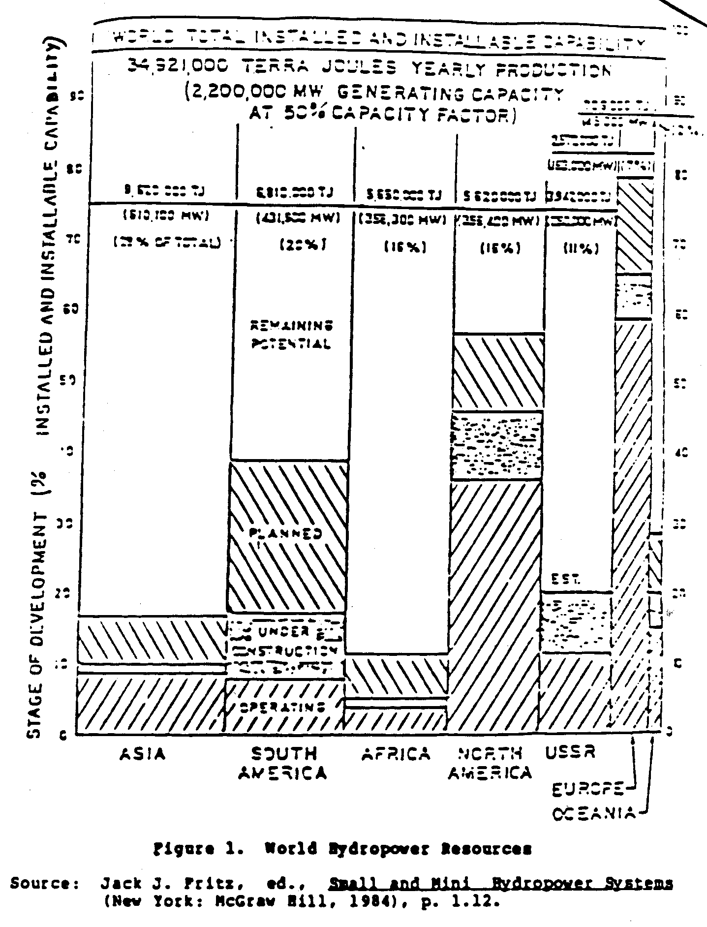
of world hydropower resources. In more scientific terms, this is known as the installed and uninstalled capability to produce energy. Directing water to flow over a pre-determined course permits energy to be extracted, whereas under natural conditions this may be impossible.
A predetermined course implies human intervention. It also implies a need for this type of energy. Need, coupled with the ability to extract energy artificially (intervention), provides the basis for a study of available resources, which in turn produces quantitative results. These results can then be used to design an appropriate hydropower system providing energy based on need, yet minimizing adverse environmental effects.
Before any detailed analysis of a hydropower system can be understood, a short history of turbines and the machinery supporting them must be presented.
HISTORY OF HYDROPOWER DEVICES
Hydraulic turbines and waterwheels are most commonly used to extract energy from falling water. Turbines as we know them today fall into two categories: reaction and impulse. Reaction turbines use both pressure and velocity forces of water to produce torque. This torque is then used to produce electrical or mechanical energy. Impulse turbines derive their torque or power from the momentum of a jet of water striking a series of blades. The waterwheel, however, is the forerunner of both the impulse and the reaction turbine.
The waterwheel, a distant grandfather of the impulse turbine, played an important role in prompting engineers such as John Smeaton of England (1724-1792) to study and improve it until its efficiency had reached about 70 percent (Arndt et al., 1981).
Development of a turbine using the same basic principles as the waterwheel was initiated by engineers Zuppinger in 1846 and Schwamkrug in 1850. An important step away from the waterwheel was initiated at that time with the development of a water spout or nozzle that directs a high-velocity stream of water against blades set in a wheel. Along with this development and the description of an efficient waterwheel as stated by Poncelet in 1826, a group of engineers from California set out to develop an impulse turbine with an efficiency higher than that of the waterwheel. Among this group was Lester A. Pelton (1829-1908), who was responsible for the development of a highly efficient impulse wheel that bears his name to this day.
The Pelton wheel, or turbine, although quite efficient, was improved by Eric Crewdson in 1920. This improvement led to the development of the Turgo wheel, which boasts even higher efficiency and simpler construction than either the Pelton wheel or the waterwheel.
Nevertheless, impulse wheels have been upstaged in recent years by more complex and efficient reaction turbines. Reaction turbines also use water momentum, but pressure forces are added for increased torque. The Kaplan or propeller turbine, developed around the time that Lester Pelton was perfecting his impulse machine, has been a very popular machine throughout its history. The Kaplan turbine's high efficiency under low beads (pressures) accounts for its growing popularity today because many installations have high flows but low heads. Other reaction turbines developed around the same time include the Francis turbine and other propeller machines.
Hybrid impulse turbines, which circumvent some basic drawbacks of full impulse machines, are known as cross-flow turbines. The first cross-flow turbine was patented by A.G.M. Michell in 1903. Professor Donat Banki also developed a cross-flow turbine in 1917 that bears his name today. Because these turbines are simple to build, they have been widely used in developing countries where both low cost and simple technology are imperative.
As we can see from the above discussion, contemporary turbine theory is a mature science. Today, the majority of research involves fine-tuning basic designs and increasing the efficiency of peripheral equipment such as governors (devices used for maintaining uniform speed in turbines) and electrical generators.
II. OPERATING PRINCIPLES
GENERAL THEORY OF TURBINES
Specific operational theory of various turbines is not within the scope of this paper. However, a general theory, covering all turbines and waterwheels, is provided in this section of the paper to aid readers in understanding the broad applications of turbines. More detailed turbine theory is generally useful only to builders or manufacturers, and is not necessary for project developers or engineers.
All hydropower machines--whether reaction, impulse, or waterwheels--are driven by the same force: gravity. Gravity causes a certain potential energy to exist in a body of water. Using this energy to provide useful work requires a change in elevation over time. Elevation change over time implies a conversion of potential energy to kinetic energy. Potential energy can be quantitatively expressed in many ways, but for the purpose of this paper, the term "head" will be used. Read is the expression of a pressure exerted on a body or part of a body in terms of feet of water. Because water is a principal fluid used in hydropower, this is a useful concept. Let us take, for example, a lake surface that is situated 1,000 meters above sea level. A hydroelectric plant is to be installed at an elevation of 800 meters above sea level using the lake water to produce power. The head, which is theoretically available to convert potential energy to kinetic energy, is 200 meters (the 200 meters is arrived at by subtracting 800 meters from 1,000 meters). This is known as gross head, or Hg. Figure 2 represents a perfect gross head, where the
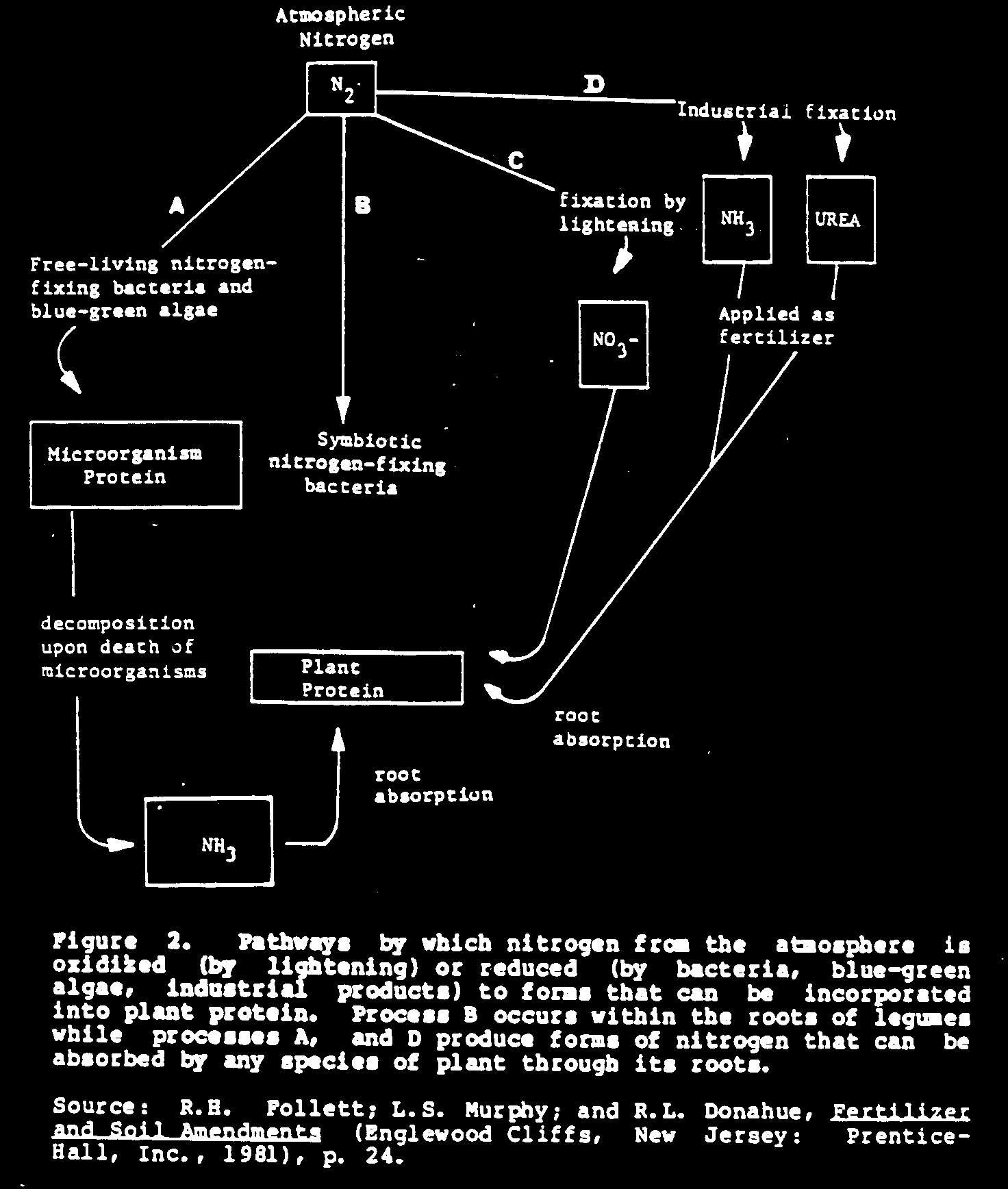
gross head is the elevation between the upper and lower water levels. In reality, this total gross head is not available to the turbine due to friction losses in delivery pipes (penstocks) and a velocity head at the outlet (tailrace) which signifies kinetic energy lost due to velocity. Once these fractional and velocity losses have been quantified in the form of head loss, they must be subtracted from the gross head. Gross head minus head losses gives the total head available to the turbine. This is called net head, or H. Once H has been determined, other major parameters describing the turbine can be defined. These are discussed in the sections that follow.
Power
Power is defined as the amount of energy that can be produced for a given H. A simple relation is given by the equation

(Equation 1)
where P is kilowatts (when metric units are used), Q is discharge at the end of the penstock, E is the efficiency of the turbine and W is the weight of the water. The power of a free jet of water streaming from the penstock is given by the equation
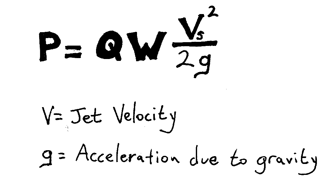
(Equation 2)
where g is the acceleration due to gravity, and V is the jet velocity.
Efficiency
The efficiency of the general power equation given in the previous section can be divided into three parts: volumetric, hydraulic, and mechanical efficiency. Volumetric efficiency is defined as the ratio of the water acting on turbine blades to the total water entering the turbine casing. For impulse turbines, nearly all the water entering strikes the blades; thus, this efficiency is close to one. The volumetric efficiency of reaction turbines is virtually the same as impulse, but waterwheels will be lower due to water spillage.
Hydraulic efficiency is defined as the power input to the turbine shaft divided by the power input to the turbine blades. This efficiency is the lowest of the three efficiencies and varies widely among designs.
The third type of efficiency is mechanical efficiency. It is defined as the power transmitted through the turbine shaft to the generator. It describes any mechanical friction losses.
The overall efficiency is the product of the three efficiencies, or:
(Equation 3)

where [E.sub.v] and [E.sub.n] and [E.sub.m] are the volumetric, hydraulic and mechanical efficiencies, respectively. This overall efficiency can be used in either designing or selecting a turbine.
Specific Speed
Another equation, independent of the type of machine, would be useful in choosing a turbine and its proper speed for a particular site, given a power capacity and net head. The equation is:
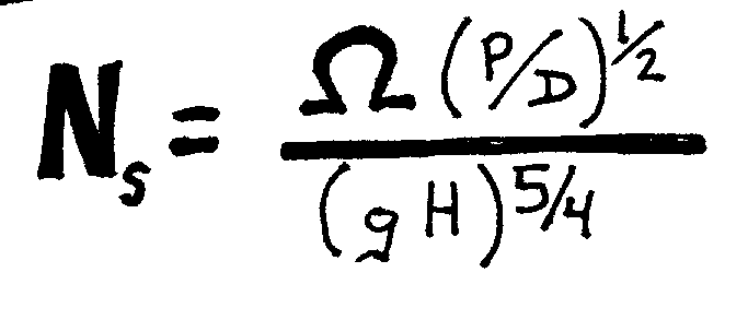
(Equation 4)
where Omega is the speed of the turbine in radians per second, D is the density of water, P is the power (as defined in equation 1), g is the acceleration due to gravity, and H is the net head. Note that because this is a dimensionless number, it can be applied to any situation.
Another specific speed that is more commonly used is given by the equation
(Equation 5)
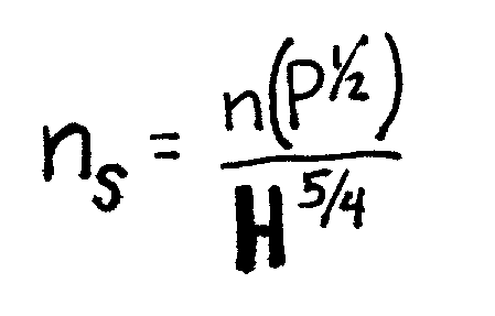
where [n.sub.s] is the speed of the turbine in revolutions per minute, P is the power in horsepower or kilowatts, and H is the net head in feet or meters. This specific speed is not dimensionless; its numerical value depends on the system of units being used. Three relationships between [N.sub.s] and [n.sub.s]--depending on the system of units--are:
[n.sub.s] = 43.5 N.sub.s
[n.sub.s] = 193.1 N.sub.s
[n.sub.s] = 166 N.sub.s.
Once the specific speed is known, the proper turbine can be selected on the basis of each turbine's rated specific speed variability. Figure 3 shows various turbines and their dimensional
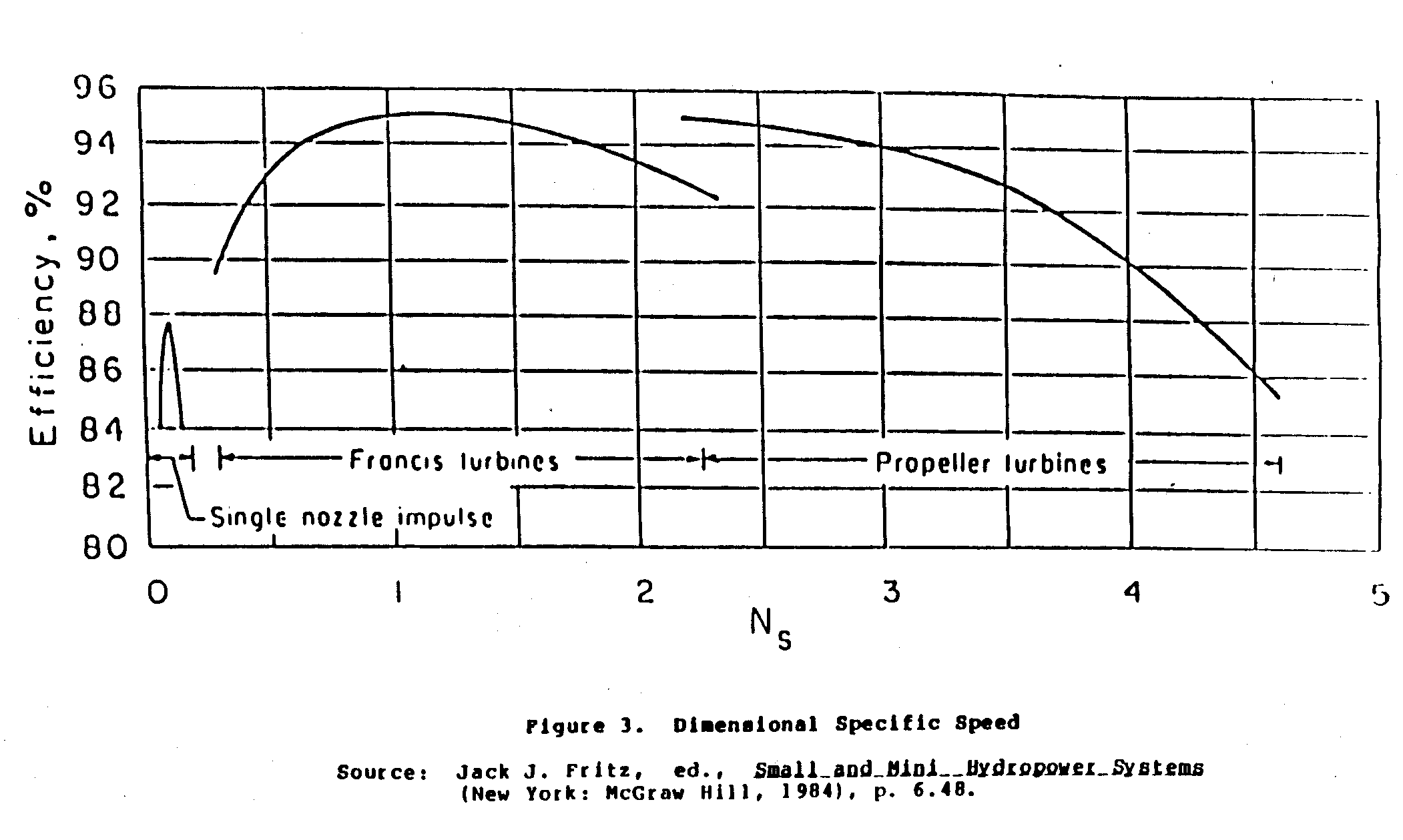
specific speeds. Waterwheels fall under Pelton and Francis turbine specific speeds, depending upon whether they are overshot ([n.sub.s] = 1 to 50) or undershot ([n.sub.s] = 30 to 100), and can reach efficiencies of 70 percent.
Selection of a particular turbine is done by determining the rpm needed (for electrical generation, rpm is rated according to the type of generator and gearing, whereas mechanical power will have installation-specific rpm requirements), and calculating the power required (based on need) and the head available (site specific). Once these parameters are determined, the specific speed can be found. As shown in Figure 3, the most efficient turbine for a particular specific speed should be used. Selection of a particular turbine also depends on cost, and the level of technology desired.
Waterwheels are more difficult to select. Head and discharge can be used to select specific designs rather than specific speed. Design manuals consider economics, low-level technology, cost, and ease of operation as high priorities in the selection of waterwheels over turbines. This implies serious consideration of waterwheel use in situations where the above factors are important.
An alternative method of turbine selection involves consideration of gross head and discharge. Turbines can be selected by using the quantities shown in Figure 4. Waterwheels are not shown in
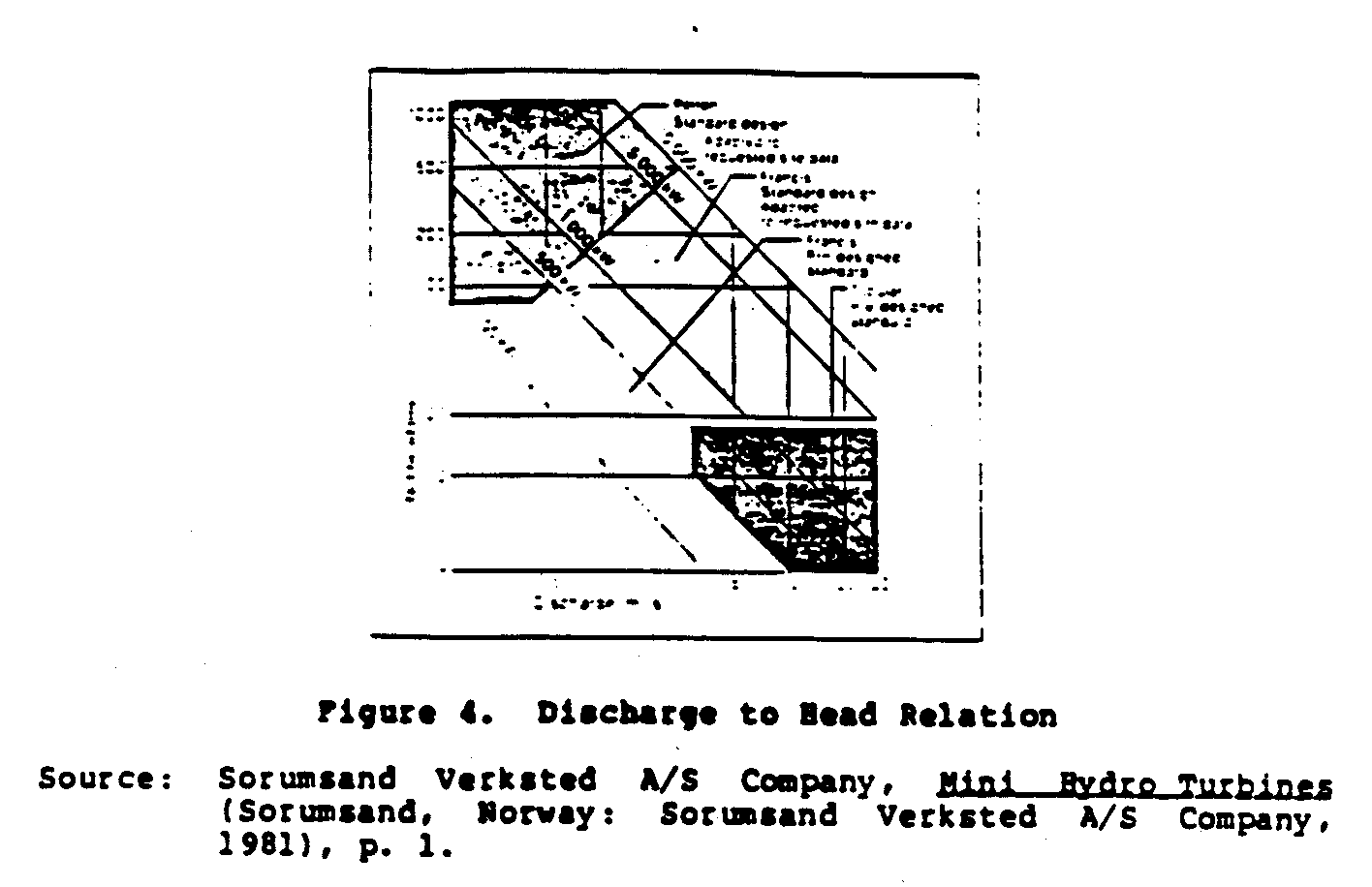
Figure 4, but they nevertheless tall under the Pelton and Francis turbine categories, probably in the lower, left corner of the figure. It should be noted here that for waterwheels, Figures 3 and 4

do not agree. This is due to the fact that waterwheels operate best under low heads and low discharges, causing the rpm to be very low. Thus, Figure 3 shows that a waterwheel can compete with a Francis turbine, whereas Figure 4 indicates use of a waterwheel, not Pelton or Francis turbines. Generally, both Pelton and Francis turbines are recommended for use with high net heads and high discharges, whereas waterwheels are meant to be used with low net heads and low discharges.
III. DESIGN VARIATIONS
TYPES OF TURBINES
Thus far, we have described specific turbines according to the names of people who developed them, without describing their physical characteristics. In this section, these characteristics are discussed to aid further in the selection of specific water-power devices. Again, to facilitate the discussion, water-power machines are grouped under the following three headings: reaction turbines, impulse turbines, and waterwheels.
Reaction Turbines
Reaction turbines use both velocity and pressure forces to produce power. Consequently, large surfaces over which these forces can act are needed. Also, flow direction as the water enters the turbine is important.
Figure 5 shows the basic design of a Francis turbine. Francis

turbines include a complex vane arrangement (see Figure 5) surrounding the turbine itself (also called the runner). Water is introduced around the runner through these vanes and then falls through the runner, causing it to spin. Velocity force is applied through the vanes by causing the water to strike the blades of the runner at an angle. Pressure forces are much more subtle and difficult to explain. In general, pressure forces are caused by the flowing water. As the water flows across the blades, it causes a pressure drop on the back of the blades. This in turn induces a force on the front, and along with velocity forces, causes torque. Francis turbines are usually designed specifically for their intended installation; with the complicated vane system, they are generally not used for microhydropower applications. Because of their specialized design, Francis turbines are very efficient yet very costly.
Propeller turbines are popular reaction machines. In Figure 6,
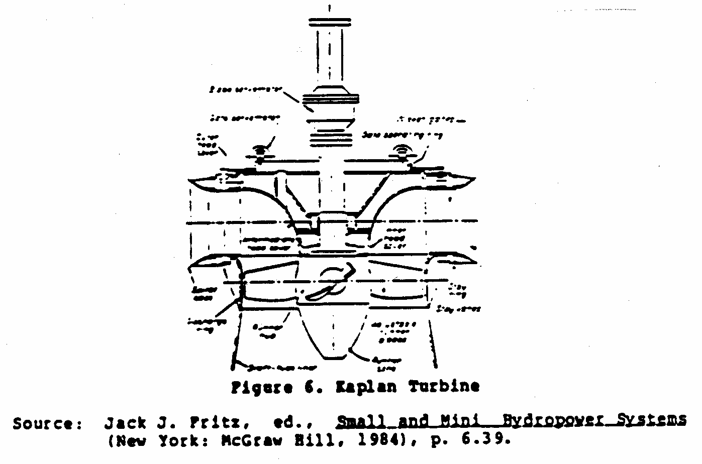
the components of a specific propeller turbine called the Kaplan are shown. Although propeller turbines operate on the same basis as the Francis turbine, they are not as specifically designed since both vanes and propellers (on the Kaplan) are adjustable. Variations include the bulb turbine which houses blades and generator in a sealed unit directly in the water stream, the stratflow turbine where the generator is attached and surrounds the blades, and the tube turbine where the penstock bends just before or after the blades, allowing a shaft connected to the blades to protrude outside the penstock and connect to the generator. Propeller turbines are usually less costly but are used almost exclusively in large installations.
The speed of reaction turbines ranges from 100 to 200 rpm, depending upon design and use. Speed is governed by the movable vanes, which alter the direction of water entering the turbine. These vanes in turn vary the pressure forces on the blades, causing a loss or gain of power and maintaining speed.
Because reaction turbines use pressure forces and thus run under reduced pressures, a phenomenon called cavitation can occur. Simply put, cavitation is the boiling of water due to low pressure. Water will boil when pressure is reduced considerably; this phenomenon happens on the low pressure side of a reaction turbine blade. Cavitation occurs only at the leading edge of the blade and as pressures rise again near the trailing edge, cavitation ceases. It is important for cavitation to cease because as the water vapor returns to a liquid state, localized pressures become tremendous. Such pressures have the equivalent force of pounding a sledge hammer against the turbine blade. Bearing in mind the power of cavitation, this phenomenon should be reduced a minimum. This is accomplished by carefully monitoring flow velocity and changing flow direction by use of the vanes. The advantages of reaction turbines include:
* high efficiencies;
* excellent power output at low heads;
* numerous designs that provide easy tailoring to specific installations; and
* the flexibility of choosing either horizontal or vertical installation.
The disadvantages of reaction turbines include:
* efficiency at specified heads and discharges but inefficiency when these vary;
* the need for accuracy in installation design;
* the possibility that cavitation will occur;
* the potential that nonuniform forces will destroy the runner;
* very strict design tolerances;
* costly civil works; and
* high manufacturing costs.
Because reaction turbines--whether Francis or propeller--have high efficiency and high power output, they are the best waterpower devices and should be pursued whenever possible.
On the other hand, these turbines are very expensive to build, highly sophisticated in design, and do not use locally-produced raw materials, making them unsuitable for use in developing countries. Note also that they may not be readily available in the small sizes needed for small installations. So, consider instead the option of using centrifugal pumps, which can be readily adapted to serve as hydroturbines in any practical power range. These pumps are readily available and come in many sizes, making it possible to satisfy the needs of the small hydropower customer. Also, because they are mass produced, they typically cost less than half as much as the equivalent hydraulic turbine. In many small-hydro applications, a suitable turbine is simply unavailable, and the cost of a custom model would be prohibitive. Centrifugal pumps are easier to install and maintain, and they are simpler to operate. In addition, they are available in a broader range of designs than conventional turbines. Wet-pit, dry-pit, horizontal, vertical, and even submersible are just a few of the types of centrifugal pumps available.
All types of centrifugal pumps, from radial-flow to axial-flow designs, can be operated in reverse and used as hydraulic turbines. Tests have shown than when a centrifugal pump operates as a turbine:
* its mechanical operation is smooth and quiet, and
* its peak efficiency as a turbine is essentially the same as its peak efficiency as a pump.
One note of caution: a centrifugal pump used as a hydraulic turbine must be checked by a qualified hydraulic engineer before it goes into operation to prevent damage to the impeller. When the pump operates as a turbine, it rotates in reverse so that operating heads and power output are generally higher. To avoid damage to the impeller, the engineer has to check how much stress the pump can tolerate caused by the flow and pressure of the water.
Impulse Turbines
Impulse turbines derive their power from a jet stream striking a series of blades or buckets. The Pelton wheel is probably the most well-known impulse machine, but others are now becoming popular.
Figure 7 shows a Pelton wheel. Notice that one nozzle is being
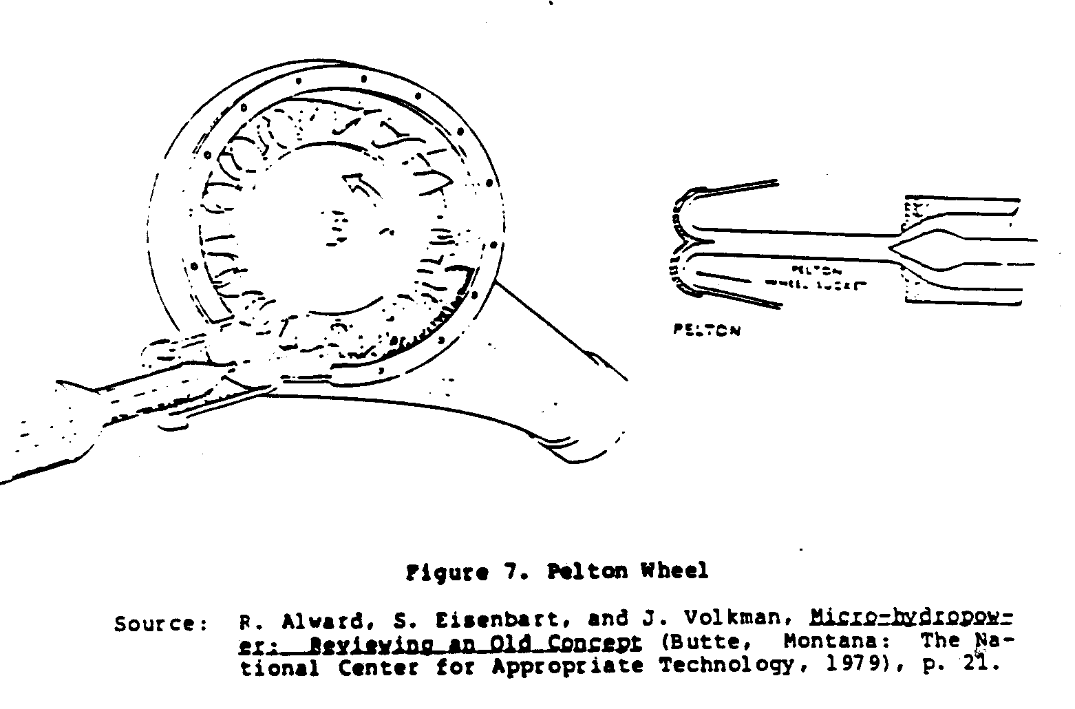
used, with its jet of water striking one bucket at a time. Since impulse turbines operate at atmospheric pressures, cavitation is not a concern. However, bucket design is very important because of the tremendous forces involved. Buckets are designed so that the stream of water is split in half and turned almost back upon itself. This design extracts maximum energy and negates axial (along the shaft) torque. Adding nozzles increases power output linearly, but a practical maximum is six nozzles. If the discharge allows more than one nozzle, this is probably desirable.
Pelton and Turgo wheels are higher speed machines ranging in speed from 1,000 to 3,600 rpm. This is advantageous when electrical generation is necessary, but high speed reduces torque which may be desirable for mechanical applications. If speed regulation in necessary, nozzle velocity can be controlled by using a needle valve which decreases the water power available.
Figure 8 shows the blade arrangement of the Turgo wheel. Designed
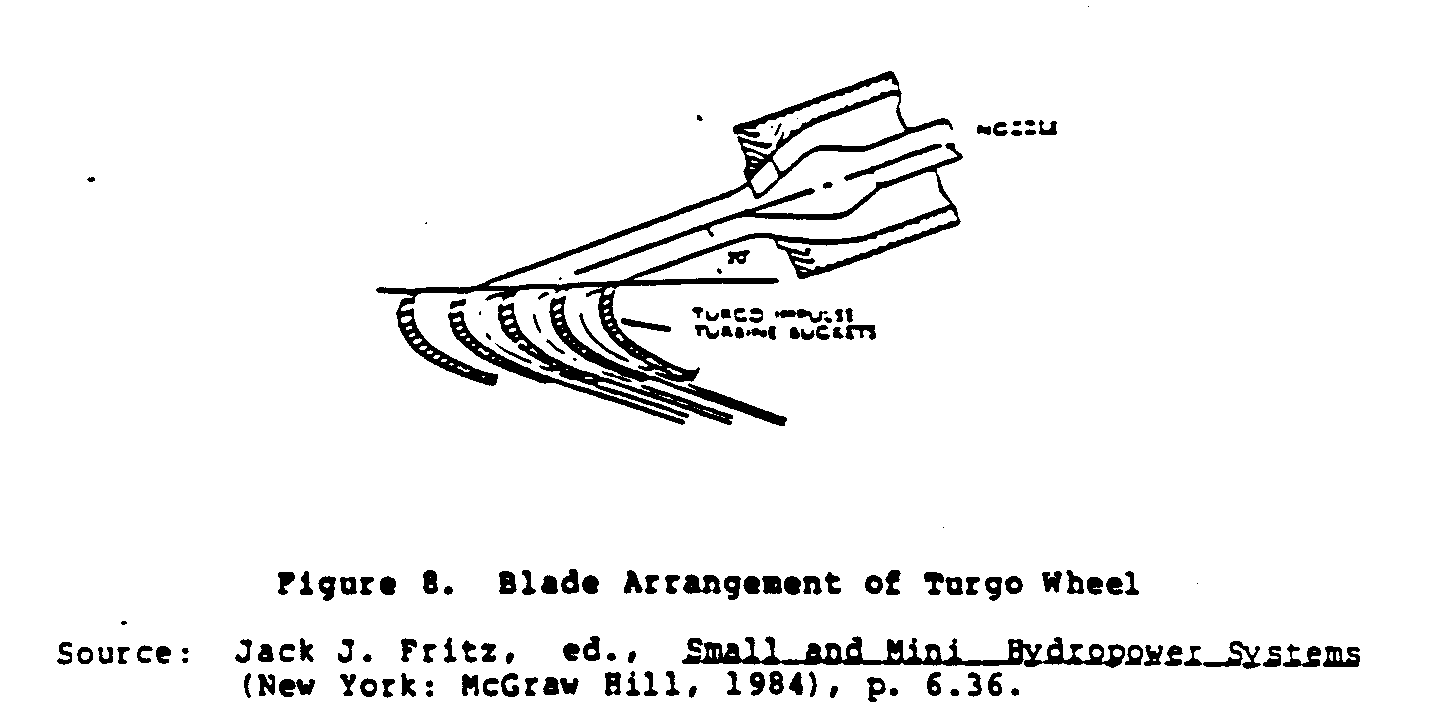
along the same lines as the Pelton wheel, the Turgo wheel allows the stream of water to strike several blades at one time. This increases the power output since one blade is always under the full force of the water jet.
Both the Pelton and Turgo wheels are well suited for high head, low discharge situations since water velocity is the governing force and may be high under high heads while discharge is low. Cross-flow turbines use impulse theory yet operate somewhat differently than Pelton or Turgo wheels. Figure 9 shows a cross-flow
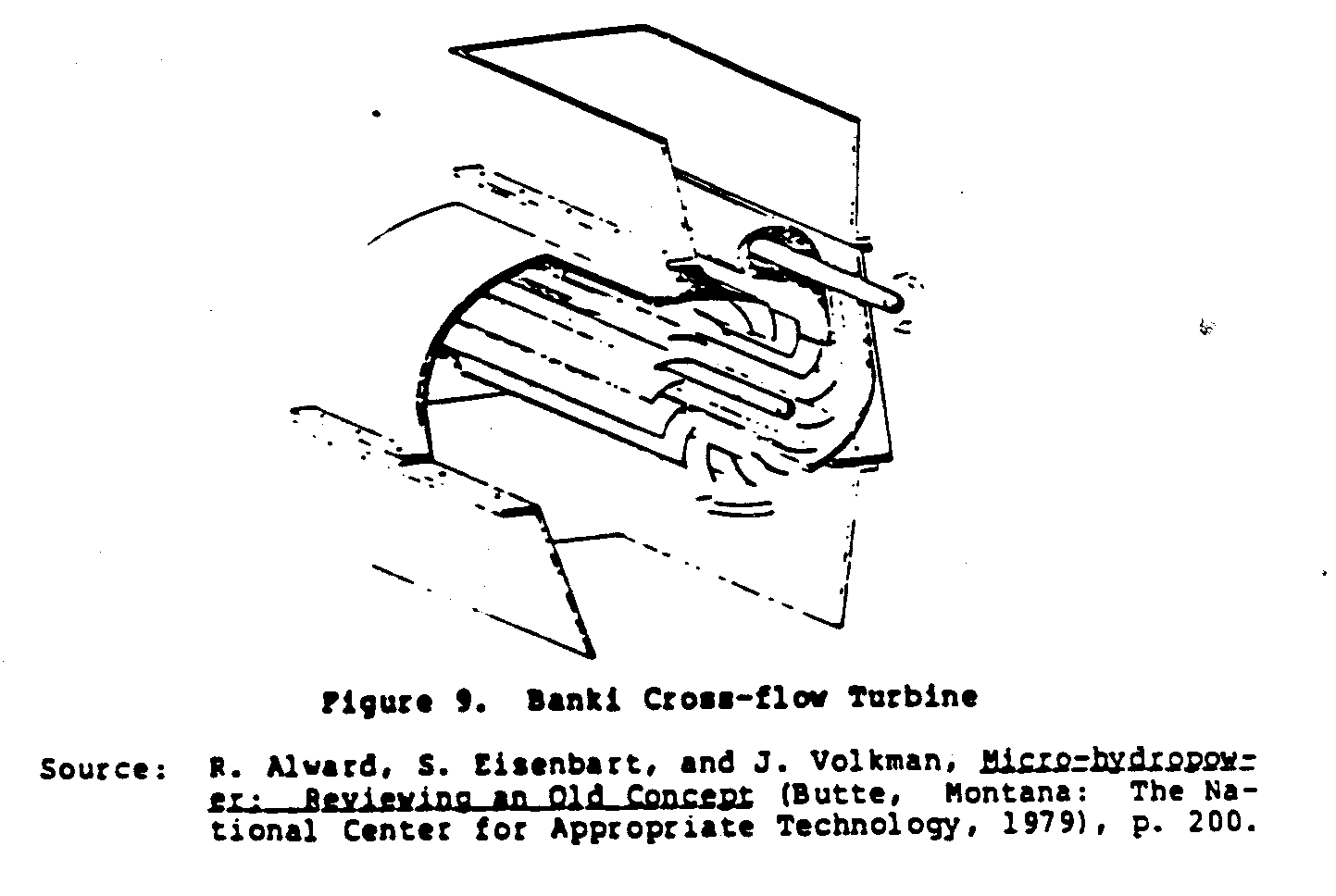
turbine called the Banki turbine. Water exiting the nozzle strikes several blades, producing torque. The blades direct the water into the inner area of the turbine. The water travels across the inner diameter of the turbine and strikes the blades again at another location on the turbine, creating additional torque. This novel design, though seemingly complex, lends itself to easy construction on a local basis since this turbine does not use a high-velocity water jet or special manufacturing techniques as do the Pelton and Turgo wheels. Local materials can be used since the force of the water is distributed evenly throughout the length of the turbine.
The operating efficiencies of impulse turbines are usually around 80 percent. Because high head, low discharge sites are common and efficiencies are high, Pelton and Turgo wheels are easily installed without the rigorous design typical of reaction turbines. Civil works are much less than those of reaction turbines since impulse turbines are independent of pressure forces.
The speed of cross-flow turbines falls in the same range as that of reaction turbines. Regulating the speed is achieved through nozzle velocity control or by diverting some water around the turbine, lessening water discharge and velocity.
The advantages of impulse turbines include:
* low water discharge requirements;
* the efficient use of high heads;
* small physical size yet high power output;
* high efficiencies;
* simple design;
* simple civil works;
* low maintenance;
* low cost; and
* low labor input.
The disadvantages of impulse turbines include:
* poor power output under low heads;
* the possibility of increased wear and tear due to operation at high speed;
* very strict manufacturing specifications for other than crossflow; and
* the complexity of regulating the speed of the turbine.
Because of their simple design and low cost, impulse turbines lend themselves well to minihydropower and microhydropower installations in remote areas in developing countries.
Waterwheels
Of all water-power machines, waterwheels are the simplest in theory, design, and installation. In this section, four types of waterwheels are described: the undershot waterwheel, the Poncelet wheel, the breast wheel, and the overshot waterwheel.
The undershot waterwheel derives its power from flowing water under a very low head. As shown in Figure 10, water passing under
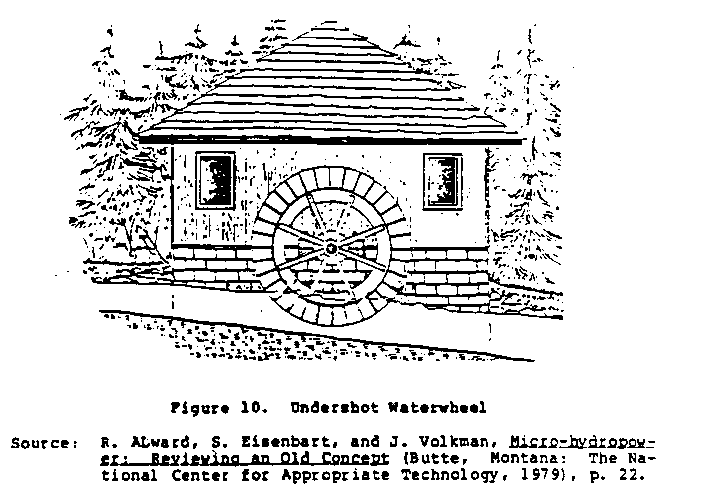
the wheel strikes the paddles, causing the wheel to rotate. Efficiency of the undershot waterwheel is quite low, and the heads ranging from 2 to 5 meters are best.
Figure 11 shows the Poncelet wheel, which is similar in design to
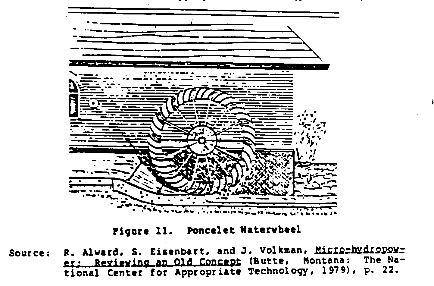
the undershot wheel. However, unlike the flat blades of an undershot wheel, the blades of a Poncelet wheel are curved, creating a more efficient water interaction by forcing the water to back up and discharge through a narrow opening. The Poncelet wheel has a minimum diameter of 4.5 meters and operates most efficiently under heads of 2 meters. Because of design improvements over the undershot wheel, efficiencies are slightly higher. A breastwork of concrete fitted close to the paddles keeps the water backed up but necessitates trash removal (trash racks) to ensure that branches or rocks will not enter the system.
The breast wheel shown in Figure 12 is another improvement over
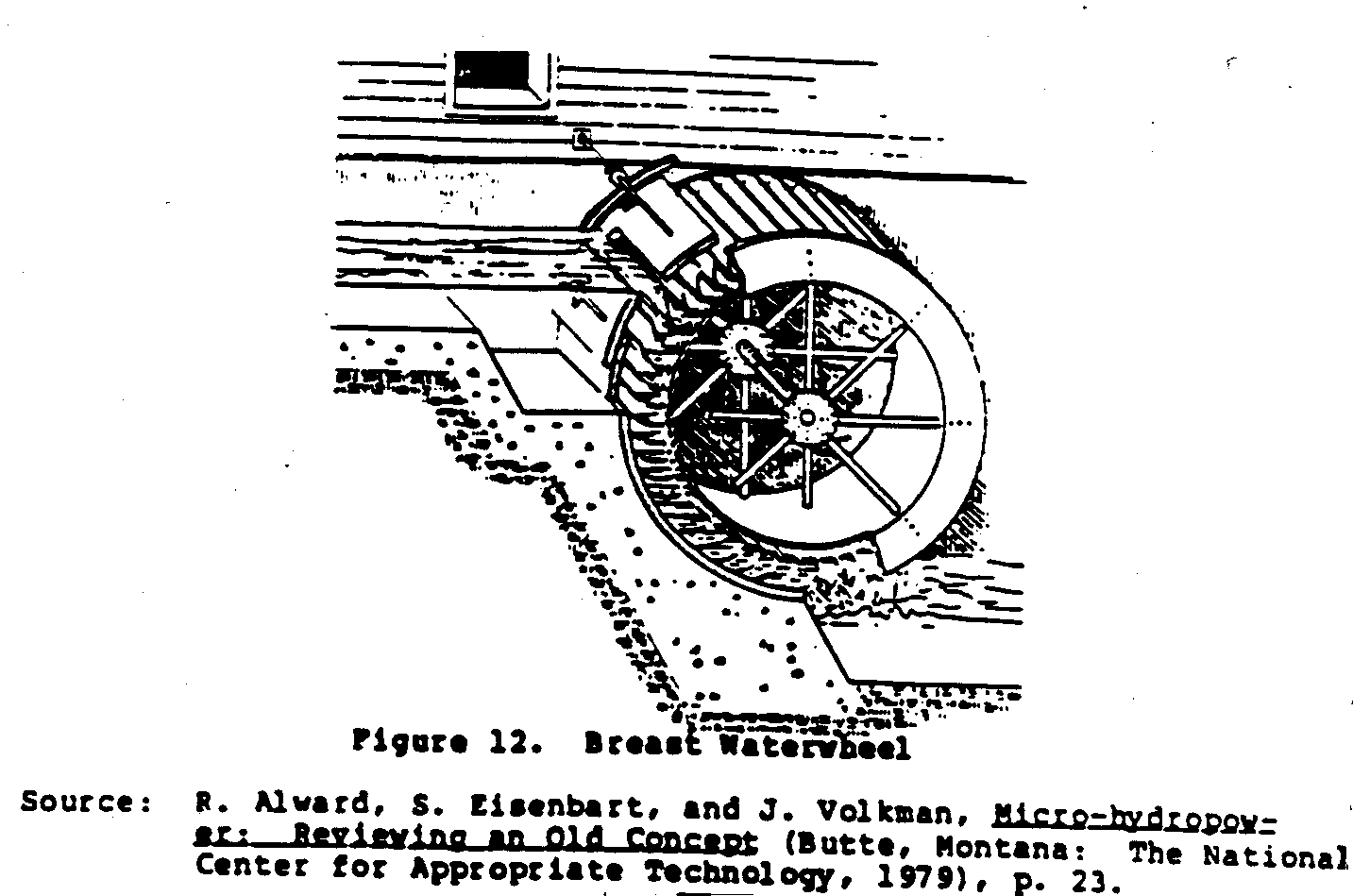
the undershot wheel. This wheel, like the Poncelet wheel, backs up the water and use the energy created therein. A close-fitting breastwork forces the water into the blades to produce torque. Efficiencies approach 65 percent for high breast wheels (water entering below the center line). The fact that breast wheels need a close-fitting breastwork, a curved bucket design, and a trash rack usually makes other types of waterwheels more attractive.
Figure 13 shows an overshot waterwheel. This design allows water
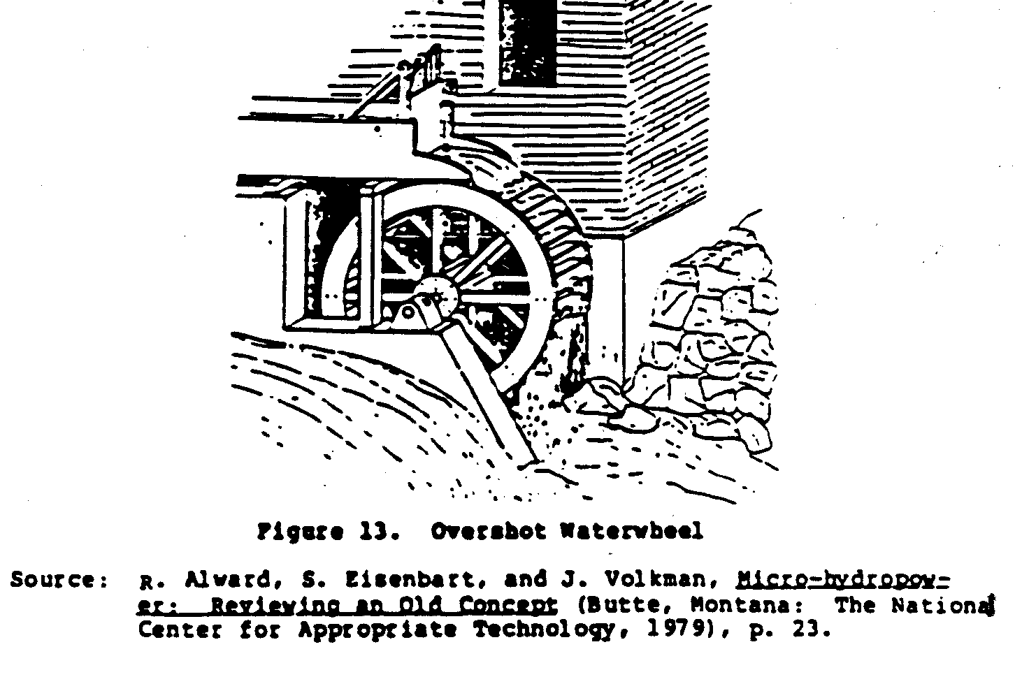
to enter buckets at the highest point, and the weight of the water causes the wheel to turn. Water discharge is controlled by a sluice gate to minimize waste through overfilled buckets. Overshot wheels are the most efficient waterwheels and can operate under heads of 3 meters and above.
Waterwheels are easy to build. They are usually large and rotate very slowly, usually in the range of 3 to 20 rpm. Waterwheels produce high torque and can be used in nonconventional ways.
The advantages of waterwheels include:
* simple design;
* easy construction;
* high torque;
* operation under large flow variations;
* minimal maintenance and repair: and
* low cost.
The disadvantages of waterwheels include:
* low efficiencies;
* need at times for close tolerances in construction;
* slow speed; and
* large size.
Waterwheels find their niche where high torque and low speed are necessary. In developing countries, the economics of construction, the level of technology, and the wide range of uses ensure waterwheels a future in water-power development.
None of the machines discussed above should be applied, however, if no practical, efficient use can be found.
USES OF HYDROPOWER
The use of waterpower falls under two general categories: mechanical and electrical use. Mechanical use implies obtaining power directly from the turbine or waterwheel and using it to accomplish physical work. Electrical use implies the generation of electricity from the turbine or waterwheel and using it to perform work.
Mechanical Use of Hydropower
Although turbines are used to produce mechanical power, they are rarely applied that way. In Third World installations, impulse wheels are used through gearing mechanisms for grinding, threshing, or cutting. These applications are appropriate to each situation. Various applications of impulse turbines include: machines that thresh, grind, and cut grain; sawmill equipment, and metalworking tools. Usually drivebelts deliver power to all of this equipment while reducing speed and increasing torque.
Waterwheels lend themselves ideally to mechanical use. The foregoing applications apply as well to waterwheels and sometimes even more so. Milling and grinding are especially conducive to waterwheels where slow rotation is necessary. Waterwheels also lend themselves well to the pumping of water or other liquids since pumps require slower speeds.
Electrical Use of Hydropower
Electrical power generation requires constant speed under varying loads. Generators operate at certain speeds, depending upon construction and electrical requirements. Uniform speed is very important and usually quite fast. Impulse and reaction turbines are used almost exclusively for electrical power generation in the United States and Europe. In the Third World, electrical power generation is becoming economical, and the use of turbines is increasing. Impulse turbines can be connected directly to a generator, but a speed regulation device must be used in combination with these turbines in order for the generator to work. Reaction turbines are usually connected to generators through a gearbox. The regulation of speed is also important in reaction turbines and can become very complex, depending upon the reaction turbine chosen.
Waterwheels do not lend themselves well to electrical power generation due to their slow speed and speed-governing problems inherent in their design. Thus, electrical power generation is not recommended with waterwheels.
COST/ECONOMICS OF HYDROPOWER
Economics dictates the feasibility of hydropower installation even if all other factors are positive. Two principal economic characteristics of hydropower are high initial costs and low operating costs. In general, a hydropower system requires substantial initial capital investments to minimize operating costs. However, there is a point where excessively high capital costs will create the reverse effect of much higher operating costs.
To reduce initial costs, several cost-cutting steps can be taken:
* maintain low administrative costs;
* use local labor;
* use local materials as much as possible;
* build some of the equipment locally;
* design an appropriate hydropower system (i.e., one that does not require high system efficiency, installation of a governor--a device used for maintaining uniform speed in a turbine, or recruitment of a full-time staff);
* do not provide for a profit margin included in most costings for microhydropower installations; and
* minimize use of costly technical expertise and supervision.
It is important to note that the steps outlined above are aimed at Third World situations and represent actual experience.
Methods for determining hydropower installation costs are difficult in Third World development situations. Nevertheless, Figure 14 gives a general idea of the relative costs of hydropower
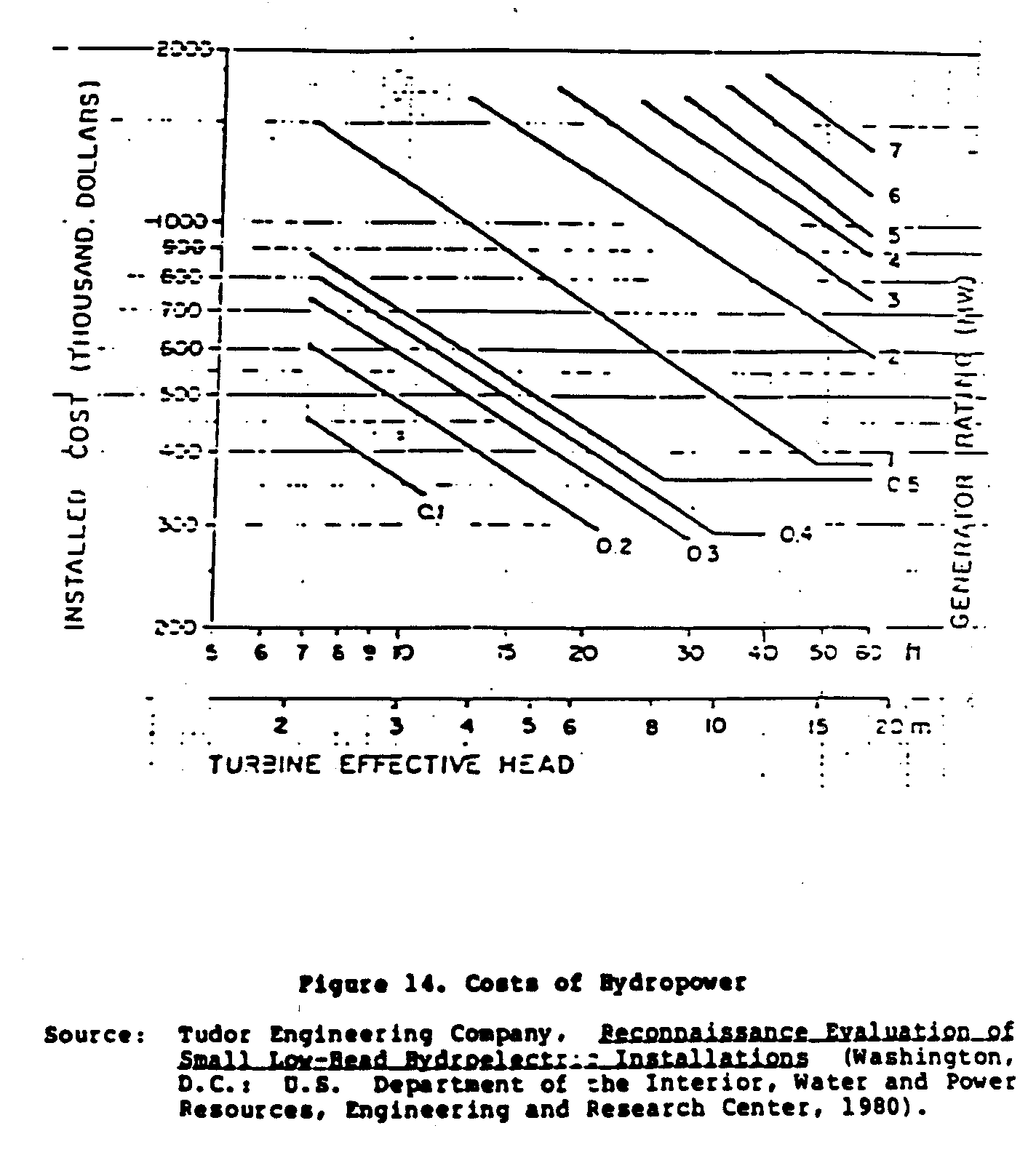
in the United States. Notice that low head, low-power installations have installed costs less than high head, high-power installations. However, notice that the cost decreases as head increases and that medium head and power output installations are the least expensive. Figure 14 shows relative costs and thus describes, for all situations, the optimum head to power ratio. Figure 14 does not factor in the cost-cutting steps listed above, however. But by taking these steps, even low head and low-power sites become economical.
Relative project costs are outlined in Figure 15. Two options are
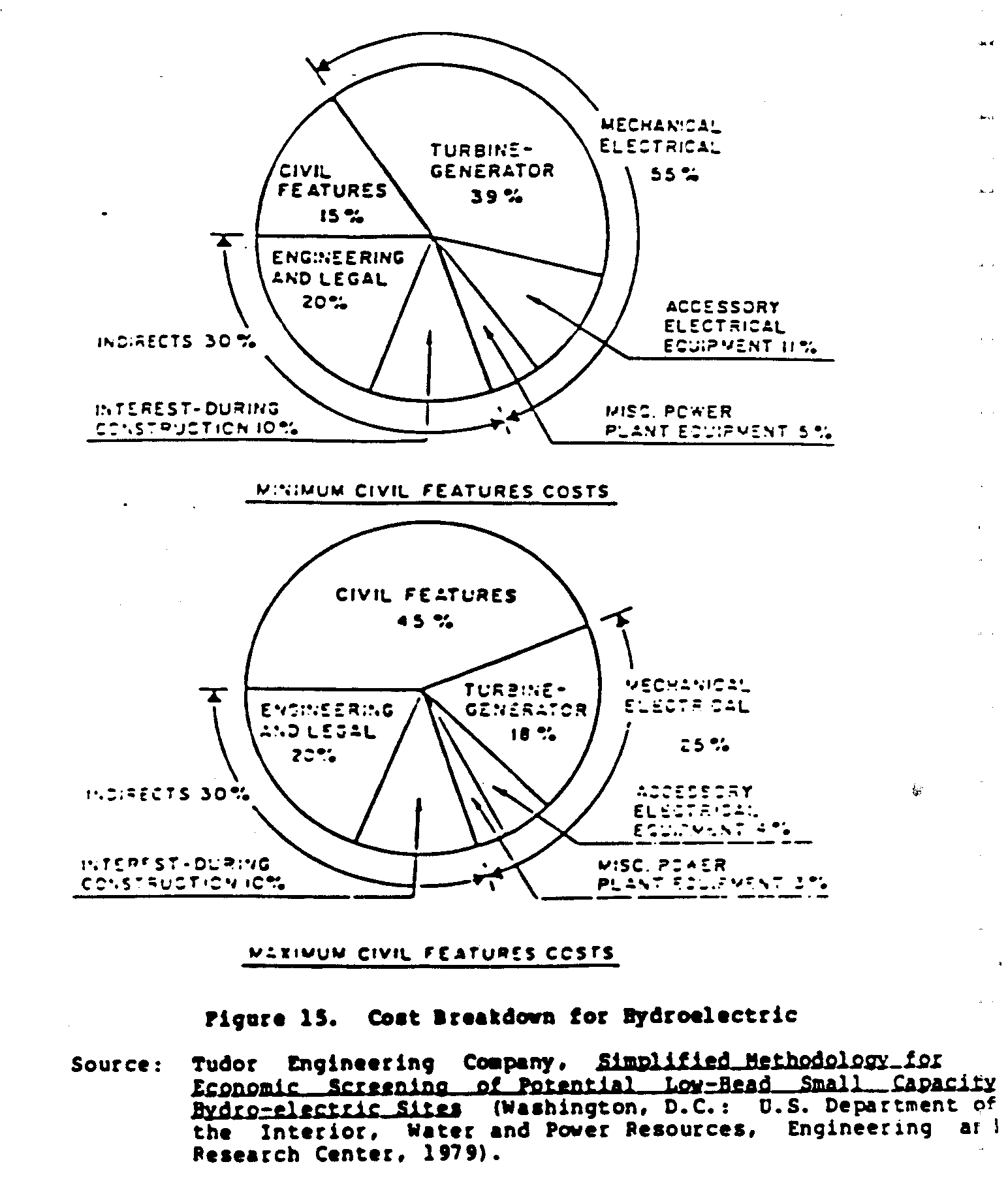
presented. The first option describes development situations in the Third World. The second option describes situations applicable to developed countries. From these two options, one can deduce that the majority of costs apply to mechanical and electrical elements and could probably be reduced by following the steps outlined previously.
This discussion demonstrates that although financial economics are important in considering hydropower installation, there are methods of reducing the financial impact to an acceptable level.
IV. COMPARING THE ALTERNATIVES
Hydropower, as previously discussed, is used primarily for electrical and motive power generation. Waterwheels are best used for motive power by direct coupling to machinery. Turbines (reaction or impulse) are best used for electrical power operation but are being used successfully for motive power as well. At this point, the question arises: "Is hydropower best for my situation, or should I use an alternate power source?" This is an important question to consider and to answer as clearly as possible. While hydropower serves some situations very well, it may be marginal or totally inappropriate for others. To determine when hydropower should be used as opposed to other alternatives, some discussion of these alternatives is necessary.
With the advent of technology transfer from technology centers in Europe and North America to developing countries, several energy sources have been perfected and successfully implemented without the supporting technology base. This has provided alternative energy sources for developing countries without the delay of technology development. Hence, solar power either through direct (photovoltaics) or indirect (steam production) methods, wind power, methane power, and alternative liquid fuel production (to name just a few) have become successful power producers in their own right. These may also become candidates for consideration along with hydropower for a particular situation. To best discuss hydropower and the alternatives, several alternative energy sources are summarized and then compared to hydropower.
SOLAR POWER
The sun provides a vast amount of energy to the earth each day. Depending upon climatic and atmospheric conditions, this energy may be harnessed and utilized. Two methods are popular (but not exclusive): photovoltaics and thermal. Photovoltaics employ silicon wafers or discs that produce electrical current in the presence of light (not necessarily restricted to visible light). When many wafers are connected together, the electricity produced may be used to power electrical machinery, electric lamps, or charge batteries. This power is in the form of direct current (DC), however, which is usually not compatible with the alternating current (AC) produced by regional electric grid systems. Thus, to power common household appliances that use AC motors, conversion from DC to AC is necessary with great losses in energy. This implies either large expenditures to produce inefficient power, or DC-compatible equipment which may be difficult to obtain.
The major drawback of photovoltaics is cost. The cost of producing silicon wafers (you have to "grow" them) is still high, despite the fact that it continues to decline steadily. Purchase of a water pump producing not more than 500 liters per minute and powered exclusively by photovoltaics would cost U.S. $7,000.00 in Kenya. This is prohibitively expensive for small communities.
Solar power may also be used to heat liquids or solids that then transport heat. Steam may be produced through intense concentrations of solar energy. This steam may be used to power a turbine (as in hydropower but with steam) for electricity or motive force. Thermal power, as created by solar energy, may also be used to heat water for domestic purposes, heat thermal masses for heat storage (passive solar heating), or even to vaporize gases as in the Minto Wheel to produce motive force.
Solar energy conversion--either by photovoltaics or thermal--may be a viable alternative to hydropower if the following conditions prevail: lack of flowing water, remoteness of site, cost, technology availability, and end use (what is the intended goal). Although solar energy can produce electrical power (DC) without the need for civil works, reservoirs, or expensive turbines and generators, photovoltaics are nevertheless expensive. Moreover, in some areas of the world, solar power is not suitable. In Darjeeling, India, for example, hydropower may be the best choice simply because of lack of sunshine during the monsoon months. Over a period of four months, the sun will not shine (except for about two weeks) because of dense cloud cover. Since power production by photovoltaics is a function of solar intensity, a huge and expensive array of solar cells would be necessary. It would in fact be prohibitively expensive. Thus, if the climatic conditions are not favorable, solar power as an alternative to hydropower must be ruled out.
WIND POWER
There is great power in the winds. The technological problem is to extract the power efficiently and without great expense. Windmills are the most popular form of power production by wind. Unfortunately, there are many designs available that claim best efficiency. Efficiency refers here to the ratio of energy produced to energy available. Available energy in the wind is great but energy produced by windmills (even the most technologically advanced) is not more than 30 percent. For development situations where high technology is scarce, typical efficiencies are less than 15 percent. This means that 85 percent of the available power has not been extracted.
As with solar power, wind power is dependent upon several factors. The most important is wind. Wind is not always available. Some developing countries are not suited for windmills simply because there is not enough wind (wind speed). Before any consideration of wind power may be entertained, data either from weather stations or from local histories must be obtained. If the average wind speed is less than about 10 km per hour, wind power will not be viable. Making effective use of wind power as an alternative to hydropower depends on the amount of wind available, availability of construction materials, expertise, and end use.
Wind power, like solar power, can become expensive when it is needed to provide large amounts of power. Wind power is best suited for motive power in pumping or turning machinery. Electrical generation by wind power is probably not viable without expensive towers, blades, governers, alternators, and batteries. This comparison to hydropower may, in situations where hydropower can be implemented, indicate that hydropower is the best choice.
METHANE
Methane gas is produced easily through fermentation of animal, crop, and human waste. By anaerobic (absence of oxygen) digestion in large containers, methane gas can be produced and used for heating, lighting, or powering internal combustion engines. This technology is rather simple but construction may be expensive and it is somewhat labor intensive.
Methane production is viable only where there are sufficient amounts of the right kind of waste. Vegetable matter (including crop residues) may be used in the digestion process but may not produce much methane due to the large cellulose content. The best waste is animal waste, which, when digested at high temperatures (about 55[degrees]C), will produce great amounts of methane. To provide this elevated temperature, all the methane produced may have to be used unless there is some other inexpensive heat source for this. Storage and transport of methane gas may be difficult and expensive. As an alternative to hydropower, methane may be the closest to actual compatibility of uses. It can replace hydropower for electrical generation and motive power by powering internal combustion engines. One problem with methane as a fuel is the high carbon dioxide, sulfur (hydrogen sulfide), and water content. All these chemicals have adverse side effects on engines when used in amounts such as those that come directly from the digester. Thus, cleaning or "scrubbing" the gas as it emerges from the digester is necessary before injection into an engine. This adds to the expense of the digester.
Both methane generation and hydropower require high capital costs but are relatively low in operating costs. Operator expertise is necessary for both, also. In sum, methane, as generated by anaerobic digestion of plant and animal wastes, presents a very viable alternative to hydropower where the necessary resources are present. Capital costs are probably lower for methane but operating costs will almost invariably be higher than those for hydropower.
LIQUID FUELS FOR INTERNAL COMBUSTION ENGINERS
The two popular fuels for internal combusion engines are gasoline (petrol) and diesel. In many parts of the world, these fuels are very difficult to obtain and are usually very expensive. Internal combustion engines are prevalent throughout the world. If other fuels can be developed to replace the expensive fossil fuels such as gasoline and diesel, they would then present viable alternatives to hydropower.
Several fuels are already in use. They include: methane (discussed previously), butane, propane, sunflower oil, and peanut oil. While there may be other possibilities, these represent the most common at this time. Butane and propane are gases which are normally used for heating or lighting. They contain high amounts of energy but are not always available, especially in remote areas. They can also be expensive to purchase and transport. Sunflower and peanut oils are just now becoming popular for diesel engines. They contain high amounts of energy but if not purified extensively, will cause contamination and subsequent destruction of the engine. None of these alternate fuels contains as high an energy content per unit volume as gasoline or diesel. Thus, more must be used to obtain the same output from an engine. Butane and propane are usually obtained from underground deposits (along with crude oil) and thus are not available worldwide. Methane, as discussed above, can be produced locally and with low technology. Sunflower and peanut oils can also be produced locally but require expensive pressing and purification processes before they can be used. If economics allow use of alternative internal combustion fuels to produce electricity and motive power, they present good alternatives to hydropower.
This description of alternatives to hydropower is not meant to be exhaustive or complete. If hydropower is a possibility for a particular situation, consideration of other alternatives is necessary from an economic, social, and end use perspective. By comparing the alternatives presented above, one can begin to determine whether or not hydropower is the best choice. However, it is very important to consider hydropower alternatives in more depth than given above. This is a technological discussion but the importance of social and cultural considerations is just as important, if not more so. Keep in mind, however, that hydropower is a very efficient, clean source of energy and should be seriously considered in light of the alternatives for a particular situation.
V. CHOOSING THE TECHNOLOGY RIGHT FOR YOU
Site selection, flow diversions, and environmental effects are among the important factors that must be considered before hydropower installation begins. The proper sequence of events must be adhered to for installation to be successful.
Economics strongly dictates the size of the hydropower site. Small hydropower sites become less economical due to the nonlinearity of costs and benefits. As the size increases, the benefit-cost ratio increases, providing more desirable outcomes. This is unfortunate, and many small installations, while seemingly ideal, are not implemented for this reason. Much has been done, however, to offset these negative economic indicators. Hydropower development in Pakistan, for example, has been encouraged through the "Small Decentralized Hydropower (SDH) program" (Inversin, 1981). This program assists in very small (micro) hydropower development and has been successful because the following objectives were met:
* readily available materials were used in nonconventional ways;
* hydropower designs were suited to the local realities; and
* the community was involved in the initiation, implementation, management, operation, and maintenance of the hydropower schemes.
Thus, small, decentralized hydropower in development situations is clearly feasible. Due to transportation, material and financial difficulties of larger hydropower installations, small-scale hydropower installations are very desirable. However, as stated previously, steps to develop hydropower on any scale must be taken carefully and in sequence.
Information on the availability of power must be obtained before any other steps are taken. Information on elevation differences, amounts of water available, and construction feasibility also must be obtained. Important preliminary questions to be answered include:
1. How much rainfall occurs over a year's time and how is it distributed throughout the year?
2. What type of water fall is available or must it be artificially induced?
3. How much water is available for use?
4. What is the topography of the area under consideration and how can it best be used?
5. Is the community willing to participate in such a project?
6. What type of community education is necessary and how will it be implemented?
If positive answers to these six questions can be obtained, subsequent steps can then be taken.
Financing also must be obtained. This can be difficult in Third World development situations where few grants or loans are available and where communities are not able to raise money themselves. If financing is unavailable, the project cannot be implemented. No hydropower project is free.
Environmental concerns are very important especially when major flow diversion or retention is required. Studies addressing the long-term effects of a hydropower project must be done. If these studies show that the environmental effects are minimal (there will always be some), the project can continue. If, on the other hand, the environmental effects are negative, reconsideration is necessary with the possibility of project termination.
If permits must be obtained, that must be done long before any design or construction is initiated.
Financial returns must be negotiated and benefits must be tabulated to ensure continuing installation viability.
Once the above steps are taken, design of the physical layout can begin. After exhaustive designs are completed, construction can begin. When the project is completed, the hydropower system must undergo rigorous testing. If the results of the tests are positive, operation of the hydropower system can begin.
VI. SUMMARY
Barnessing the energy from falling water is a relatively easy technology compared to internal combusion engines. By applying the methods described in this paper, abundant and clean power can be appropriately obtained.
BIBLIOGRAPHY
Alward, R.; Eisenbart, S.; and Volkman, J. Micro-hydropower: Reviewing an Old Concept. Butte, Montana: The National Center for Appropriate Technology, 1979.
Arndt, R.E.A.; Farell, C.; and Wetzel, J.M. "Hydraulic Turbines." Paper presented at the Small Scale Hydropower Feasibility Studies Seminar of the University of Minnesota, Minneapolis, Minnesota, 26-30 July, 1981.
Arndt, R.E.A.; Farell, C.; and Wetzel, J.M. "Hydraulic Turbines." In Small and Mini Hydropower Systems, pp. 6.1-6.64. Edited by Jack J. Fritz. New York: McGraw Hill, 1984.
Breslin, W.R. Small Michell (Banki) Turbine: A Construction Manual. Arlington, Virginia: Volunteers in Technical Assistance, 1980.
Deudney, Daniel. "Rivers of Energy: The Hydropower Potential." Worldwatch Paper 44. Washington, D.C.: The Worldwatch Institute, June 1981.
Durali, M. Design of Small Water Turbines for Farms and Small Communities. Prepared for the Office of Science and Technology, United States Agency for International Development by the Technology Adaptation Program, Massachusetts Institute of Technology, Cambridge, Massachusetts, 1976.
Fraenkel, P. The Power Guide: A Catalogue of Small Scale Power Equipment. New York: Charles Scribner's Sons, 1979.
Fritz, Jack J., ed. Small and Mini Hydropower Systems. New York: McGraw Hill, 1984.
Hamm, H.W. Low Cost Development of Small Water Power Sites. Arlington, Virginia: Volunteers in Technical Assistance, 1967.
Inversin, A.R. A Case Study: Micro-hydropower Schemes in Pakistan. Washington, D.C.: National Rural Electric Cooperative Association, 1981.
McGuigan, D. Harnessing Water Power for Home Energy. Charlotte, Vermont: Garden Way Publishing Company, 1978.
Ovens, W.G. A Design Manual for Water Wheels. Arlington, Virginia: Volunteers in Technical Assistance, 1975.
Sorumsand Verksted A/S Company. Mini Hydro Turbines. Sorumsand, Norway: Sorumsand Verksted A/S Company, 1981.
Tudor Engineering Company. Reconnaissance Evaluation of Small Low-Head Hydroelectric Installations. Washington, D.C.: U.S. Department of the Interior, Water and Power Resources, Engineering and Research Center, 1980.
Volunteers in Technical Assistance. Overshot Waterwheel: Design and Construction Manual. Arlington, Virginia: Volunteers in Technical Assistance, 1979.
SUGGESTED READING LIST
Microhydropower Handbook Volume I and II. Available from U.S. Department of Commerce, National Technical Information Service, 5285 Port Royal Road, Springfield, Virginia 22161 at U.S. $32.50 for Volume 1 (DE83-006-697) and $31.00 for Volume II (DE83-006-698). Written for persons who want to design their own site for producing electricity of under 100 kilowatts output. With over 800 pages (both volumes included), this is probably the most comprehensive work on the subject.
Harnessing Water Power for Home Energy, by Dermat McGuigan. This book, published by Garden Way Publishing, gives examples of microhydroelectric projects from all over the world. It is a good introduction to hydropower. Priced in most book stores at under U.S. $8.00.
Micro-Hydro Power: Reviewing an Old Concept, by the National Center for Appropriate Technology, P.O. Box 3838, Butte, Montana 59702-3838. This publication provides a good overview of microhydropower for a moderate price (less than U.S. $5.00).
Guide to Development of Small Hydroelectric and Microhydroelectric Projects in North Carolina, by John Warren and Paul Gallimore. This handbook on hydropower is available from the North Carolina Alternative Energy Corporation, Research Triangle Park, North Carolina 27709.
More Other Homes and Garbage: Designs for Self-Sufficient Living. Published by the Sierra Club. Pages 75-92 deal with producing electricity from a stream. This book, like all of the other books listed above, includes techniques for measuring head and stream flow.
Homemade Electricity: An Introduction to Small-Scale Wind, Hydro, and Photovoltaic Systems. Available from Superintendent of Documents, U.S. Government Printing Office, Washington, D.C. 20402.
Directory of Manufacturers of Small Hydropower Equipment, by Allen R. Inversin. Available from the Small Decentralized Hydropower (SDH) Program, International Programs Division of the National Rural Electric Cooperative Association, 1800 Massachusetts Avenue N.W., Washington, D.C. 20036.
ORGANIZATIONS TO CONTACT FOR ASSISTANCE
DEVELOPMENT ORGANIZATIONS
The National Center for Appropriate Technology P.O. Box 3838 Butte, Montana 59701 USA
Volunteers in Technical Assistance Suite 200 1815 North Lynn Street Arlington, Virginia 22209 USA
ARCHITECTS/ENGINEERS, CONSULTANTS, AND CONSTRUCTION FIRMS
The following are design firms, consultants, and contractors with expressed interest in hydropower development. This list encompasses a spectrum ranging from small consultant firms with minimal hydropower experience to large engineering firms that can manage a project from conception through construction. A potential user of the services of any of the firms listed should satisfy himself that the firm has the capability and experience required for the service desired.
U.S. Firms
Edward A. Abdun-nur Consulting Engineer 3067 South Dexter Way Denver, CO 80222 USA (303) 756-7226
Acres American Liberty Bank Building Main at Court Buffalo, NY 14202 USA (716) 853-7525
Allen & Boshall, Inc. Engineers-Architects-Consultants Attn: W. Lewis Wood, Jr. P.O. Box 12788 Memphis, TN 38112 USA (901) 327-8222
Anderson-Nichols 661 Harbour Way South Richmond, CA 94804 USA (415) 237-5490
Applied Energy Planners, Inc. Attn: E. Fletcher Christiansen, Pres. P.O. Box 88461 Atlanta, GA 30338 USA (404) 451-8526
Appropriate Technologies, Inc. Attn: George L. Smith P.O. Box 1016 Idaho Falls, ID 83401 USA (208) 529-1611
Associated Consultants, Inc. Attn: R.E. Palmquist 3131 Fernbrook Lane North Minneapolis, MN 55441 USA (612) 559-5511
Auslam & Associates, Inc. Economic Consultants Attn: Margaret S. Hall 601 University Avenue Sacramento, CA 95825 USA
Ayres, Lewis, Norris & May, Inc. 3983 Research Park Drive Ann Arbor, MI 48104 USA
Banner Associates, Inc. Attn: Joseph C. Lord P.C. Box 550 309 South Fourth Street Laramie, WY 82070 USA (307) 745-7366
Barber Engineering Attn: Robert W. Ross, Project Coordinator 250 South Beechwood Avenue, Suite 111 Boise, ID 83709 USA (208) 376-7330
Barnes, Henry, Meisenheimer & Grende Attn: Bruce F. Barnes 4658 Gravois Avenue St. Louis, MO 63116 USA (314) 352-8630
Barr Engineering Company Attn: L.W. Gubbe, Vice President 6800 France Avenue South Minneapolis, MN 55435 USA (612) 920-0655
Beak Consultants Incorporated Environmental Consultants Attn: Bruce Eddy, Fishery Biologist Eighth Floor Loyalty Building 317 S. W. Alder Portland, OR 97204 USA (503) 248-9507
Bechtel National, Inc. Attn: G.D. Coxon, Business Development Representative, Research Engineering P.O. Box 3965 San Francisco, CA 94119 USA
Beling Consultants, Inc. Attn: Tom Brennan Beling Building 1001-16th Street Moline, IL 61265 USA (309) 757-9800
Benham-Holway Powergroup Southland Financial Center 4111 South Darlington Tulsa, OK 74135 USA (918) 663-7622
Berger Associates Attn: Richard H. Miller P.O. Box 1943 Harrisburg, PA 17105 USA (717) 763-7391
Bingham Engineering Attn: Jay R. Bingham, President 165 Wright Brothers Drive Salt Lake City, UT 84116 USA (801) 532-2520
Black & Veatch Attn: P.J. Adams, Partner Acting Head of Power Division P.O. Box 8405 Kansas City, MO 64114 USA (913) 967-2000
Boeing Engineering & Construction P.O. Box 3707 Seattle, WA 98124 USA (206) 773-8891
Booker Associates, Inc. Attn: Franklin P. Eppert, Vice President 1139 Olive Street St. Louis, MO 63101 USA (314) 421-1476
Bookman-Edmonston Engineering Attn: Edmond R. Bates, P.E. 600 Security Building 102 North Brand Boulevard Glendale, CA 91203 USA (213) 245-1883
Booz, Allen & Hamilton, Inc. 4330 East-West Highway Bethesda, MD 20814 USA (301) 951-2200
Bovey Engineers, Inc. Attn: George Wallace East 808 Sprague Avenue Spokane, WA 99202 USA (509) 838-4111
Boyle Engineering Corporation Attn: D.C. Schroeder 1501 Quail Street P.O. Box 3030 Newport Beach, CA 92663 USA (714) 752-0505
Brown & Root, Inc. Attn: C.W. Weber, Vice-President 4100 Clinton Drive P.O. Box 3 Houston, TX 77001 USA (713) 678-9009
Burgess & Niple, Ltd. 5085 Reed Road Columbus, OH 43220 USA (614) 459-2050
Burns & McDonnell Engineers-Architects-Consultants Attn: J.C. Hoffman P.O. Box 173 Kansas City, MO 64141 USA (816) 333-4375
Burns & Roe, Inc. 550 Kinderkamack Road Oradell, NJ 07649 USA (212) 563-7700
Lee Carter Registered Professional Engineer 622 Belson Court Kirkwood, MO 63122 USA (314) 821-4091
C.E. Maguire, Inc. Attn: K. Peter Devenis, Senior Vice President 60 First Avenue Waltham, MA 02254 USA (617) 890-0100
C.H. Guernsey & Company Consulting Engineers & Architects Attn: W.E. Pack National Foundation West Building 3555 N.W. 58th Street Oklahoma City, OK 73112 USA (405) 947-5515
C.T. Male Associates, P.C. 3000 Tracy Road Schenectady, NY 12309 USA (518) 785-0976
CH2M Hill, Inc. Attn: R.W. Gillette, Director of Power Generation 1500 114th Avenue, S.E. Bellevue, WA 98004 USA (206) 453-5000
Center 4 Engineering Attn: Gale C. Corson, P.E. 523 South 7th Street, Suite A P.O. Drawer A Redmond, OR 97756 USA (503) 548-8185 Chas. T. Main, Inc. Attn: R.W. Kwiatkowski, Vice President Southeast Tower Prudential Center Boston, MA 02199 USA (617) 262-3200
Chasm Hydro, Inc. Attn: John Dowd, President Box 266 Chateaugay, NY 12920 USA (518) 483-7701
Childs & Associates Attn: Thomas R. Childs 1317 Commercial Billingham, WA 98225 USA (206) 671-0107
Clark-McGlennon Associates, Inc. Attn: Peter Gardiner 148 State Street Boston, MA 02109 USA (617) 742-1580
Cleverdon, Varney & Pike, Inc. Attn: Thomas N. St. Louis 126 High Street Boston, MA 02110 USA (617) 542-0438
Clinton-Anderson Engineering, Inc. Attn: Carl V. Anderson 13616 Gamma Road, Suite 101 Dallas, TX 75234 USA (214) 386-9191
Converse, Ward, Davis, Dixon, Inc. Geotechnical Consultants Attn: Kenneth B. King, Principal Engineer The Folger Building, Suite A 101 Howard Street San Francisco, CA 94105 USA (415) 543-7273
Crawford, Murphy & Tilly, Inc. Attn: Robert D. Wire 2750 West Washington Street Springfield, IL 62702 USA (217) 787-8050
Cullinan Engineering Co., Inc. Attn: William S. Parker P.O. Box 191 200 Auburn Street Auburn, MA 01501 USA (617) 832-5811
Curran Associates, Inc. Attn: R.G. Curran, President 182 Main Street Northampton, MA 01060 USA (413) 584-7701
Dames & Moore 445 South Figueroa Street, Suite 3500 Los Angeles, CA 90071 USA (213) 683-1560
Daverman & Associates, P.C. Architects-Engineers Attn: Gary C. Knapp 500 South Salina Syracuse, NY 13202 USA (315) 471-2181
Davis Constructors & Engineers, Inc. P.O. Box 4-2360 Anchorage, AK 99509 USA (907) 344-0571
Dhillon Engineers, Inc. Consulting Electrical Engineers Attn: B.S. Dhillon, President 1600 S.W. 4th Avenue, Suite 603 Portland, OR 97201 USA (503) 228-2877
DMJM Hilton Attn: R.W. Baunach, P.E. Suite 1111 421 S.W. 6th Avenue Portland, OR 97204 USA (503) 222-3621
Donohue & Associates, Inc. Engineers and Architects Attn: Stuart C. Walesh, Resources Engineering Department Milwaukee Division 600 Larry Court Waukesha, WI 53186 USA (414) 784-9200
Dravo Engineers and Constructors Attn: S. T. Maitland, Project Manager One Oliver Plaza Pittsburgh, PA 15222 USA (412) 566-3000
DuBois & King, Inc. Engineering & Environment Services Attn: Maxine C. Neal Route 66 Randolph, VT 05060 USA (802) 728-3376
Ebasco Services, Inc. Attn: R.E. Kessel, Manager of Proposal Development 2 Reactor Street New York, NY 10006 USA
Edward C. Jordan Company Attn: E.C. Jurick, Client Relations P.O. Box 7050, Downtown Station Portland, ME 04112 USA (207) 775-5401
Eicher Associates, Inc. Ecological & Environmental Consultants 8787 S.W. Becker Drive Portland, OR 97223 USA (503) 246-9709
Electrak Incorporated Attn: R.M. Avery 6525 Belcrest Road, Suite 209 Hyattsville, Maryland 20782 USA (301) 779-6868
Electrowatt Engineering Services Attn: U.M. Buettner 1015 18th Street, N.W., Suite 1100 Washington, D.C. 20036 USA (202) 659-9553
Emery & Porter, Inc. Attn: D.B. Emery, President 3750 Wood Street Lansing, MI 48906 USA (517) 487-3789
Energy Research & Applications, Inc. 1301 East El Segundo Boulevard El Segundo, CA 90245 USA (213) 322-9302
Energy Services, Inc. Attn: Dr. Jay F. Kunze Two Airport Plaza, Skyline Drive Idaho Falls, ID 83401 USA (208) 529-3064
Energy Systems Corporation Attn: K.E. Mayo, President 23 Temple Street Nashua, NH 03060 USA (603) 882-0670
Engineering & Design Associates Attn: Stanley D. Reed Senior Principal 6900 Southwest Haines Road Tigard, OR 97223 USA (503) 639-8215
Engineering Hydraulics, Inc. Attn: Glen Rockwell, President 320 South Sunset Street P.O. Box 1011 Longmont, CO 80501 USA (303) 651-2373
Engineering-Science, Inc. Attn: G.S. Magnuson, Vice President 125 West Huntington Drive Arcadia, CA 91006 USA (213) 445-7560
Engineers Incorporated of Versont Attn: Kenneth W. Pinkham, P.E. P.O. Box 2187 South Burlington, VT 05401 USA (802) 863-6389
Espey, Huston & Associates, Inc. Engineering & Environmental Consultants Attn: Sandra Hix P.O. Box 519 Austin, TX 78767 USA (512) 327-6847
Exe Associates - Consulting Engineers Attn: David A. Exe 428 Park Avenue P.O. Box 1725 Idahol Falls, ID 83401 USA (208) 529-0491
F.A. Villela & Associates, Inc. Civil Engineers Attn: Frank A. Villela, President 308 Walker Avenue South Wayzata, MN 55391 USA (612) 475-0848
Fay, Spofford & Thorndike, Inc. Attn: B. Campbell, Vice President One Beacon Street Boston, MA 02108 USA (617) 523-8300
Fluid Energy Systems, Inc. Attn: K.T. Miller, President/Director 2302 32nd Street, #C Santa Monica, CA 90405 USA (213) 450-9861
Ford, Bacon & Davis Utah, Inc. Attn: B.G. Slighting 375 Chipeta Way P.O. Box 8009 Salt Lake City, UT 84108 USA (801) 583-3773
Foster-Miller Associates, Inc. 135 Second Avenue Waltham, MA 12154 USA (617) 890-3200
Foth & Van Dyke Associates, Inc. 2737 South Ridge Road P.O. Box 3000 Green Bay, WI 54303 USA
Foundation Sciences, Inc. Attn: R. Kenneth Dodds, President 1630 S.W. Morrison Street Portland, OR 97205 USA
Frederiksen, Kamine & Associates, Inc. Attn: Francis E. Borcalli, Associate 1900 Point West Way, Suite 270 Sacramento, CA 95815 USA (916) 922-5481
Geo Hydro Engineers, Inc. Attn: Leland D. Squier, President 247 Washington Avenue Marietta, GA 30060 USA (404) 427-5050
Geothermal Surveys, Inc. 99 Pasadena Avenue South Pasadena, CA 91030 USA (213) 255-4511
Gibbs & Hill, Inc. Attn: E.F. Kenny, Director Planning & Development 393 Seventh Avenue New York, NY 10001 USA (212) 760-5279
Gilbert-Commonwealth Attn: C.A. Layland, Manager Government Marketing 525 Lancaster Avenue P.O. Box 1498 Reading, PA 19603 USA (215) 775-2600
Hall and Associates, Inc. Attn: Ronald R. Hall, President 1515 Allumbaugh P.O. Box 7882 Boise, ID 83707 USA (208) 377-2780
Halliwell Associates, Inc. 589 Warren Avenue East Providence, RI 02914 USA (401) 438-5020
Haner, Ross & Sporseen, Inc. Attn: J.H. Greenman 15 S.E. 82nd Drive, Suite 201 Gladstone, OR 97027 USA (503) 657-1384
Hansa Engineering Corporation Attn: Kurt A. Scholz, President 500 Sansome Street San Francisco, CA 94111 USA (415) 362-9130
Harding-Lawson Associates P.O. Box 578 Novato, CA 94948 USA (415) 892-0821
Mike Harper Professional Engineer P.O. Box 21 Peterborough, NH 03458 USA (603) 924-7757
Harrison-Western Corporation Attn: Eldon _rickle 1208 Quail Street Lakewood CO 80215 USA (303) 234-0273
Harstad Associates, Inc. 1319 Dexter Avenue North P.O. Box 9760 Seattle, WA 98109 USA (206) 285-1912
Harza Engineering Company Attn: Leo A. Polivka, Group Management Director 150 South Wacker Drive Chicago, IL 60606 USA (312) 855-7000
Hoskins-Western-Sonderegger, Inc. Attn: J.M. Carpenter, Dev. Coord. 825 "J" Street P.O. Box 80358 Lincoln, NE 68501 USA (402) 475-4241
Hoyle, Tanner & Associates. Inc. Attn: H.D. Hoyle, Jr., President One Technology Park Londonderry, NH 03053 USA (603) 669-5420
Hubbell, Roth & Clark, Inc. (HRC) Environmental Consulting Engineers Attn: George Hubbell, II P.O. Box 824 2323 Franklin Road Bloomfield Hills, MI 48013 USA (313) 338-9241
Hydro Research Science 3334 Victor Court Santa Clara, CA 95050 USA (408) 988-1027
Hydrocomp 201 San Antonio Circle Mountain View, CA 94040 USA (415) 948-3919
Hydrogage, Inc. Attn: David C. Parsons, Hydrometric Specialist P.O. Box 22285 Tampa, FL 33623 USA (813) 876-4006
Hydrotechnic Corporation Attn: A.H. Danzberger, Vice President 1250 Broadway New York, NY 10001 USA (212) 695-6800
International Engineering Company, Inc. 180 Howard Street San Francisco, CA 94105 USA (415) 442-7300
J.E. Sirrine Co. of Virginia P.O. Box 5456 Greenville, SC 29606 USA (803) 298-6000
J.F. Sato and Associates Attn: James F. Sato, President 6840 South University Boulevard Littleton, CO 80122 USA (303) 779-0667
J. Kenneth Fraser & Associates Attn: J.K. Fraser 620 Washington Avenue Rensselaer, NY 12144 USA (518) 463-4408
JBF Scientific Corporation 2 Jewel Drive Wilmington, MA 01887 USA (617) 657-4170
James Hansen and Associates Attn: James C. Hansen P.O. Box 769 Springfield, VT 05156 USA (802) 885-5785
James M. Montgomery, Consulting Engineers, Inc. Attn: Clifford R. Forsgren, P.E. 1301 Vista Avenue Boise, ID 83705 USA (208) 345-5865
Jason M. Cortell & Associates, Inc. Environmental Consultants Attn: Susan R. Thomas, Marketing Coordinator 244 Second Avenue Waltham, MA 02145 USA (617) 890-3737
John David Jones & Associates, Inc. Attn: Paul E. McNamee 5900 Roche Drive Columbus, OH 43229 USA (614) 436-5633
Jordan/Avent & Associates Attn: Frederick E. Jordan, President 111 New Montgomery Street San Francisco, CA 94105 USA (415) 989-1025
Joseph E. Bonadiman Attn: J.C. Bonadiman P.O. Box 5852 606 East Mill Street San Bernadino, CA 92412 USA
Kaiser Engineers, Inc. Attn: C.F. Burnap, Project Development 3000 Lakeside Drive P.O. Box 23210 Oakland, CA 94623 USA (415) 271-4111
Kleinschmidt & Dutting Attn: R.S. Kleinscnmidt 73 Main Street Pittsfield, ME 04967 USA (207) 487-3328
Klohn Leonoff Consultants, Inc. Attn: Earl W. Speer, President Suite 344 3000 Youngfield Street Denver, CO 80215 USA (303) 232-9457
Lane Construction Corporation Attn: D.E. Wittmer, Vice President-Engineering Box 911 Meriden, CT 06450 USA (203) 235-3351
Lawson-Fisher Associates Attn: John E. Fisher 525 West Washington Street South Bend, IN 46601 USA (219) 234-3167
Livingston Associates Consulting Geologists, P.C. Attn: C.R. Livingston 4002 Green Oak Drive Atlanta, GA 30340 USA (404) 449-8571
M L B Industries, Inc. Attn: Thomas M. Eckert, Operations Manager 21 Bay Street Glen Falls, NY 12801 USA (518) 798-6814
McGoodwin, Williams & Yates, Inc. Attn: L.C. Yates, President 909 Rolling Hills Drive Fayetteville, AR 72701 USA (501) 443-3404
Mead & Hunt, Inc. 2320 University Avenue P.O. Box 5247 Madison, WI 53705 USA (608) 233-9706
Michael Baker, Jr., Inc. Engineers & Surveyors Attn: Wayne D. Lasch, Project Engineer 4301 Dutch Ridge Road Box 280 Beaver, PA 15009 USA (412) 495-7711
Myron Anderson & Associates Civil Consultants Attn: Myron Anderson 16830 N.E. 9th Place Bellevue, WA 98008 USA (206) 747-3117
Normandeau Associates, Inc. Environmental Consultants Attn: Joseph C. O'Neill, Marketing Coordinator 25 Nashua Road Bedford, NH 03102 USA (603) 472-5191
North American Hydro, Inc. Attn: Charles Alzberg P.O. Box 676 Wautoma, WI 54982 USA (414) 293-4628
O'Brien & Gere Engineers, Inc. Justin & Courtney Division Attn: J.J. Williams, Vice President 1617 J.F. Kennedy Boulevard Suite 1760 Philadelphia, PA 19103 USA (215) 564-4282
Oscar Larson & Associates P.O. Box 3806 Eureka, CA 95501 USA (707) 443-8381
Parsons Brinckerhoff One Penn Plaza New York, NY 10001 USA (212) 239-7900
Perini Corporation Attn: R.G. Simms, Vice President-Marketing 73 Mt. Wayte Avenue Framingham, MA 01701 USA
Frank R. Pollock Consulting Engineer 6367 Verde Court Alexandria, VA 22312 USA (703) 256-3838
PRC Engineering Consultants, Inc. P.O. Box 3006 Englewood, CO 80155 USA (303) 773-3788
Presnell Associates, Inc. Attn: David G. Presnell, Jr. 200 West Broadway, Suite 804 Louisville, KY 40202 USA (502) 587-9611
R.W. Beck & Associates Attn: Richard Lofgren 200 Tower Building Seattle, WA 98101 USA (206) 622-5000
Radiation Management Corporation Environmental Consultants Attn: C.E. McGee, Director-Technical Marketing 3508 Market Street Philadelphia, PA 19104 USA (215) 243-2950
Raven Systems & Research Inc. Environmental Consultants Attn: John Dermody, Hydrographic Engineer 2200 Sixth Avenue, Suite 519 Seattle, WA 98121 USA (206) 621-1126
Resource Consulting Group, Inc. Attn: Gary Goldner, Associate 51 Brattle Street Cambridge, MA 02138 USA (617) 491-8315
Resource Planning Associates, Inc. Attn: A. Ashley Rooney 44 Brattle Street Cambridge, MA 02138 USA (617) 661-1410
Rist-Frost Associates Attn: Fil Fina, Jr., Partner 21 Bay Street Glens Falls, NY 12801 USA (603) 524-4647
Robert E. Meyer Consultants Attn: B. Tanovan, Manager-Water Resources Department 14250 S.W. Allen Boulevard Beaverton, OR 97005 USA (503) 643-7531
Ross & Baruzzini, Inc. Attn: Donald K. Ross 7912 Bonhomme Avenue St. Louis, MO 63105 USA (314) 725-2242
Russ Henke Associates Attn: Russ Henke P.O. Box 106 Elm Grove, WI 53122 USA (414) 782-0410
Science Applications, Inc. Attn: John A. Dracup 5 Palo Alto Square, Suite 200 Palo Alto, CA 94304 USA (415) 493-4326
SCS Consulting Engineers, Inc, 4014 Long Beach Boulevard Long Beach, CA 90807 USA (213) 427-7437
Shawinigan Engineering Corporation Attn: James H. Cross 100 Bush Street, 9th Floor San Francisco, CA 94104 USA (415) 433-7912
Soil Systems, Inc. Attn: Robert L. Crisp, Jr. 525 Webb Industrial Drive Marietta, GA 30062 USA (404) 424-6200
Southern Engineering Co. of Georgia Attn: J.W. Cameron Main Office 1000 Crescent Avenue, N.E. Atlanta, GA 30309 USA (404) 892-7171
Spooner Engineering - North Attn: John A. Spooner, Partner 7 Fulton Avenue Oshkosh, WI 54901 USA (414) 231-1188
Stanley Consultants, Inc. Stanley Building Muscatine, IA 52761 USA
Stone & Webster Engineering Corp. Attn: J.N. White, Vice President 245 Summer Street Boston, MA 02107 USA
Storch Engineers Attn: Herbert Storch 333 East 57th Street New York, NY 10022 USA (212) 371-4675
STS Consultants, Ltd. Hydraulics & Hydrology Attn: Constantine N. Papadakis Wolverine Tower, Suite 1014 3001 South State Street Ann Arbor, MI 48104 USA (313) 663-3339
Sutherland, Ricketts & Rindahl, Consulting Engineers, Inc. Attn: Donald D. Ricketts 2180 South Ivanhoe Street Denver, CO 80222 USA (303) 759-0951
Sverdrup & Parcel Associates, Inc. Attn: D.L. Fenton, Vice President 800 North 12th Boulevard St. Louis, MO 63101 USA (314) 436-7600
System Control, Inc. Attn: W.H. Winnard 1901 N. Fort Myer Drive, Suite 200 Arlington, VA 22209 USA (703) 522-5770
Terrestial Environmental Specialists, Inc. R.D.1, Box 388 Phoenix, NY 13135 USA (315) 695-7228
Tetra Tech, Inc. Attn: R.L. Notini, Engineer 630 North Rosemead Boulevard Pasadena, CA 91107 USA (213) 449-6400
The Kuljian Corporation Attn: Dr. T. Mukutmoni, Vice President-Research Engineering 3624 Science Center Philadelphia, PA 19104 USA (215) 243-1972
Tippitts-Abbett-McCarthy-Stratton (TAMS), Engineers & Architects Attn: Eugene O'Brien, Partner 655 Third Avenue New York, NY 10017 USA (212) 867-1777
Tudor Engineering Company Attn: David C. Willer 149 New Montgomery Street San Francisco, CA 94105 USA
Turbomachines, Inc. Attn: John W. Roda, President 17342 Eastman Street Irvine, CA 92705 USA
United Technologies Research Center Silver Lane East Hartford, CT 06108 USA (203) 565-4399
Veselka Enginering Consultants, Inc. Attn: A. William Veselka, P.E. 325 South Mesquite Street Arlington, TX 76010 USA (817) 469-1671
W.A. Wahler & Associates Attn: J.L. Marzak, Vice President 1023 Corporation Way P.O. Box 10023 Palo Alto, CA 94303 USA (415) 968-6250
Whitman Requardt & Associates Attn: Henry A. Naylor, Jr. 1111 North Charles Street Baltimore, MD 21201 USA (301) 727-3450
Wilsey & Ham 1035 East Hillsdale Boulevard Foster City, CA 94404 USA (415) 349-2151
Wind & Water Power P.O. Box 49 Harrisville, NH 03450 USA (603) 827-3367
Woodward-Clyde Consultants Attn: Joseph D. Bortano, Sr. Project Engineer 3 Embarcadero Center, Suite 700 San Francisco, CA 94111 USA (415) 956-7070
Richard S. Woodruff Consulting Engineer 4153 Kennesaw Drive Birmingham, AL 35213 USA (205) 879-8102
Wright, Pierce, Barnes & Wyman Attn: L. Stephen Bowers, Vice President-Marketing 99 Main Street Topsham, ME 04086 USA (207) 725-8721
Non-U.S. Firms
Crippen Consultants Attn: R.F. Taylor, P.E. 1605 Hamilton Avenue North Vancouver, B.C. Canada V7P 2L9 (604) 985-4111
Engineering & Power Deveopment Consultants, Limited Marlowe House, Sidcup Kent, DA15 7AU England (01-300 3355)
Montreal Engineering Co., Ltd. Attn: G.V. Echkenfelder, Vice President P.O. Box 777, Place Bonaventure Montreal, Quebec, Canada H5A 1E3
Motor-Columbus Consulting Engineers Parkstrasse 27 CH-5401 Baden, Switzerland (617-875-6171)
Shawinigan Engineering Corporation Suite 310 33 City Centre Drive Mississanga, Ontario, Canada L5B 2N5 (416) 272-1300
Sogreath Consulting Engineers 47, Avenue Marie-Reynoard 38100 Grenoble, France (76) 09.80.22
SUPPLIERS/MANUFACTURERS
PRIME MOVERS
Independent Power Developers, Inc. Pelton and propeller units, Route 3, Box 285 company systems Sandpoint, ID 83864 USA
The James Leffel Company Francis/propeller/Hoppes units Springfield, OH 45501
Associated Electric Company 54 Second Avenue Chicopee, MA 01020 USA (Manufacturer Representative)
Gilberg, Gilkes & Gordon, Ltd. Wide range of turbines from Westmorland, England LA9 7BZ 10 KW to multi-megawatt, Turgo and Kendal
Small Hydroelectric Systems Pelton, with power range 5 P.O. Box 124 to 25 KW for heads from 50 Custer, WA 98240 USA to 350 feet
Cssberger Turbinenfabrik Crossflow (Michell or Banki D-8832 Weissenberg type) turbines of 1 to 1000 KW Postfach 425 Bayern, West Germany
Westward Mouldings, Ltd. Fiberglass water wheels Greenhill Works, Delaware Road Gunnislake, Cornwall, England
Campbell Water Wheel Company Water wheels 420 South 42nd Street Philadelphia, PA 19104 USA
Manitou Machine Works, Inc. 14 Morris Avenue Cold Spring, NY 10516 USA
GSA Associates Francis units 223 Katonah Avenue Katonah, NY 10536 USA
Niagara Water Wheels, Ltd. Four models of propeller 706 E. Main Street turbines with power in range Welland, Ontario L3B 3Y4, Canada of 20 to 250 KW
Barber Hydraulic Turbines, Ltd. Propeller and Francis Barber Point, P.O. Box 340 turbines Welland, Ontario L3B 3Y4, Canada
Canyon Industries Francis, miniature turbine 5346 Mosquito Lake Road set offering 50 to 750 watts Deming, WA 98244 USA
New Found, Inc. Small crossflow turbines Route 138 Hope Valley, RI 02832 USA
Northern Water Power Company Axial flow propeller turbines P.O. Box 49 with output range from 20 to Harrisville, NH 03450 USA 250 KW
Alaska Wind and Water Power Pelton turbines P.O. Box G Chigiak, AK 99567 USA
Pumps, Pipe and Power Pelton turbines Kingston Village Austin, NE 89310 USA
Obermeyer Hydraulic Turbines Crossflow and Pelton 10 Front Street turbines Collinsville, CT 06020 USA
Leroy-Somer Siphon turbines 16 Passaic Avenue Fairfield, NJ 07006 USA
Belle Hydroelectric Crossflow turbines 3 Leatherstocking Street Cooperstown, NY 13326 USA
Maine Hydroelectric Belfast turbines Development Groups Goose Rocks, ME 04046 USA
Allis Chalmers Large turbines Hydro Turbine Division P.O. Box 712 York, PA 17405 USA
MISCELLANEOUS EQUIPMENT SUPPLIERS
Windworks Gemini inverter Box 329, Route 3 Mukwonago, WI 53149 USA
Lima Electric Company, Inc. AC alternator 200 East Chapman Road Box 918 Lima, OH 45802
Woodward Governor Company Mechanical governor 5001 N. 2nd Street Rockford, IL 61101 USA
Natural Power, Inc. Governor New Boston, NH 03070 USA