ISBN: 0-86619-017-1
FIRST PRINTING FEBRUARY 1967 REPRINTED 1975 REPRINTED FEBRUARY 1976 REPRINTED FEBRUARY 1977 REPRINTED APRIL 1977 REPRINTED AUGUST 1991
Prepared By: VITA 1600 Wilson Boulevard, Suite 500 Arlington, Virgnia 22209 USA Tel: 703/276-1800 * Fax: 703/243-1865 Internet: pr-info@vita.org
Introduction
The VITA Solar Cooker was especially designed to be sturdy, relatively easy to make, easy to repair, and low in cost. It uses the principle of the Fresnel reflector which concentrates light and heat by using several simple reflecting surfaces. Most other cookers use a doubly-curved reflecting surface. The VITA Fresnel design has a number of advantages:
-It gives a broad uniform focal region the size of the cooking pot rather than a sharp, intense spot of heat, making it safer and more efficient;
-Rings can be added or removed to increase or decrease the cooker's power output;
-The solar cooker described in this manual is designed to give enough heat for the cooking needs of a medium-sized family (3-5 children),
-to use cheap readily available materials. In the United States the materials used are mainly Masonite sheet, aluminized Mylar, wood, and iron strip. In both the United States and Morocco, the cost of materials is about three dollars ($3.00). In developing countries the Mylar will have to be imported but it is lightweight and inexpensive,
-to be as simple as possible.
The VITA Solar Cooker requires more labor than, for example, forming a paraboloidal reflector by spinning an aluminum sheet; the labor requirement may make it uneconomical for developed countries, but this cooker was designed specifically for developing ones.
Before one decides to begin manufacturing this solar cooker, there are some serious drawbacks that should be considered carefully. It is generally agreed that an average of 2,000 or less hours of sunlight per year is too little for the cooker to be practical. It should also be pointed out that the cooker will be more effective in dry climates and high altitudes.
The cooker is not effective early in the morning or late in the afternoon; therefore it could not be used by people who ordinarily eat their large meal in the evening. Also the women must accept doing their cooking outside in the open.
Though the cooker is not difficult to use once one is accustomed to it, it does require some instruction. Experience in Morocco indicates that learning to use it is about like learning to knit; therefore one can probably not expect a "natural" market to exist; one must be prepared to follow up manufacturing with personal introduction.
Although the cooker construction is not difficult, spreading the Mylar on the glued Masonite is tricky and requires some practice. One will probably ruin the first few cookers in the process of learning. Therefore it is probably impractical to plan on making fewer than a dozen or so cookers as a start.
Lastly, and perhaps most importantly, one wants to be sure that other cooking procedures are comparatively quite expensive. Exactly how much time or money does the average family spend on obtaining fuel and hence how long would it take to recover the initial investment by savings on fuel costs? This is probably an important consideration in a subsistence agricultural economy where there is not much cash available. Also, of course, the cooker can never be used all the time so it can never substitute completely for convential cooking methods.
I. TOOLS AND MATERIALS
This section lists all the tools and materials needed to build the VITA Solar Cooker. The best choice of materials may vary from place to place. Other kinds of wood or composition board may be cheaper than the materials indicated here in some countries. Any sheet material such as plywood or certain sheet metals, can substitute for the Masonite.
A. Reflecting Surface
Tools
Fine sandpaper Paint brush Safety razor blade or sharp knife Clean, dry, lint-free cloth Two (2) spoons Rubber blade window washer (squeegee) or a smooth stiff rubber windshield wiper Rubber roller (double print photograph roller) Four (4) boards 5 =. x 5 cm. x 135 cm. Hammer and coping saw (bandsaw if available) Ruler and pencil
Materials
About 120 cm. x 120 cm. Masonite (0.3 cm. to 0.6 cm. thick) as free as possible of pits and structure defects, 80% - 95% ethyl alcohol approximately 50 cc/cooker Epoxy cement (resin, hardener, and solvent 80% - 95% alcohol) approximately 75 cc. of mixed cement Clean dry cup Clean smooth stick (size of pencil) A roll of aluminized Mylar (.0005" thickness) 160 cm. wide Polyurethane paint or if not available use good oil paint
B. Frame
Tools
Paint brush Ruler and pencil Protractor Hammer, hand saw Screw driver Drill capable of drilling metal (6 mm. diameter) Vise
Materials
15 cm. strip of 18 mm. x 3 mm. hot rolled iron Two (2) 2 cm. x 120 cm. boards (oak for strength but pine or other woods are sufficient) Two dozen aluminum nails (or screws) about 5 cm. long (or other non-rusting material) 10 cm. x 6 mm. bolt with fitting wing nut
C. Utensil Holder
Tools
Ruler and pencil Drill capable of drilling metal (6 mm. diameter) Cold chisel or metal cutting hand saw Vise
Materials
40 cm. strip of 18 mm. x 3 mm hot rolled iron 50 cm. strip of 18 mm. x 3 mm. hot rolled iron Wood stock 25 mm. x 25 mm. x 80 cm. preferably a hard wood Two (2) 25 mm. x 6 mm. steel bolts and fitting wing nuts One (1) 11 cm. x 6 mm. steel bolt with fitting wing nuts One (1) 3 cm. x 6 mm. steel bolt with fitting nut
II. HOW TO MAKE THE VITA SOLAR COOKER
Note: Be sure you feel you can complete all the steps before starting construction.
Construction can be divided into nine parts:
1. Applying a sealing finish to the Masonite 2. Making the surface smooth and dust free 3. Applying thin uniform coat of adhesive 4. Applying the aluminized "Mylar" 5. Cutting out the rings 6. Preparing the legs 7. Bending the rings into shape and mounting them on the legs 8. Providing a cooking vessel support 9. Providing an adjustable brace
- Applying a sealing finish to the Masonite (to keep the Masonite from absorbing glue and moisture).
A. If the 120 cm. x 120 cm. Masonite is rough to the touch, sand it smooth with medium sandpaper. If it 1s already smooth, this step can be omitted.
B. Brush polyurethane paint smoothly on both sides of the Masonite, covering all areas. If polyurethane paint is not available, a coat of epoxy cement may be used in the front side (the side to be used as the reflector), and varnish or lacquer may be used on the back. Do not use varnish or lacquer on the front.
C. Let the paint dry on a dust-free area.
D. Clean the brush with oil base paint thinner (or alcohol for varnish, or water for epoxy).
- Making the front surface smooth and dust free.
A. Choose the smoother side of the Masonite as the front (or the side with epoxy already on it.)
B. Using a safety razor blade, remove major imperfections, such as drip marks, from this front side.
C. Rub the surface smooth with steel wool or fine sandpaper, until it feels very smooth to the touch. If it does not, apply another coat of sealer to the smooth side, let it dry and sand it again.
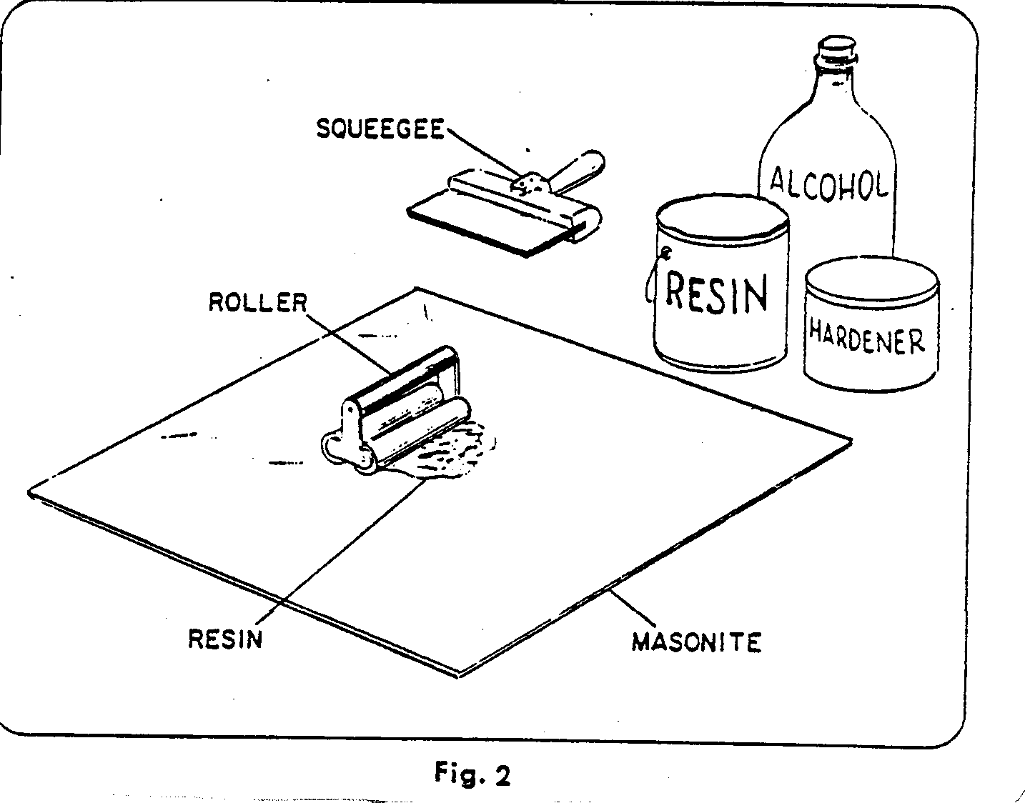
D. From scrap wood cut out four (4) wedges 10 cm. long and 5 cm. high as shown in Fig. 2. These will be used in part 4.
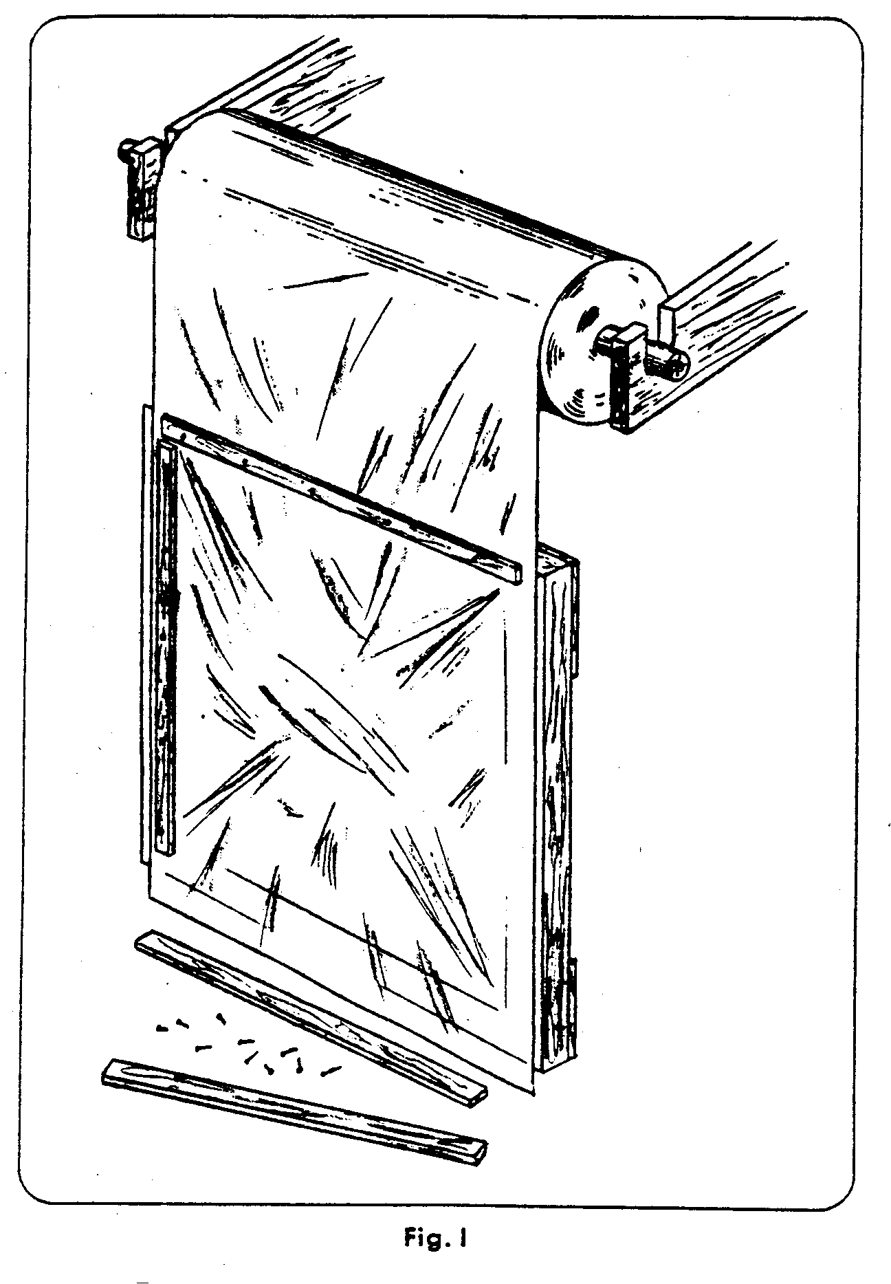
E. Nail four (4) pieces of scrap wood into a 150 cm. square frame as shown in Fig. 1. This will be used in step 4.
- Applying a thin uniform coat of adhesive. See Fig. 2.
Note: Before you prepare the epoxy, complete steps 4A and 4B so that the Mylar will be ready to be glued.
A. Some important notes to remember about epoxy-resin cements:
The cement hardens in about 20 minutes on the tools and in a bit longer time when spread on the Masonite. Once hardened, it will not dissolve again even in its own solvent. Before hardening it may be dissolved in water, but once water is added it will never harden. Wash all tools and containers which touch the cement with water before it hardens if you want to use them again. Do not let water come into contact with the cement being used for the actual cementing. Do not mix hardener and resin except when actually preparing to use it. Do not put a spoon covered with hardener into the resin can. Do not put a spoon covered with resin into the hardener.
B. Mix equal portions of hardener, resin and 80% - 95% alcohol in a clean dry cup with a clean smooth stick. Two tablespoons or six teaspoons of each should be sufficient.
C. Dust the Masonite surface with a clean, dry, lint-free cloth immediately before applying the prepared cement. Place the Masonite on a table or a similar large flat surface, preferably above the ground, to lessen the amount of dust that will settle on the surface while you are working.
D. Pour the prepared cement on the center of the Masonite and spread it evenly over all the surface in a very thin coat with a stiff squeegee or rubber blade. Use long, smooth strokes to prevent ridges and press down quite hard. (See Fig. 2.)
E. Roll the cemented surface with a double-print roller until the surface appears shiny and uniform from a glancing angle. Work out ridges and regions of varying thickness by going back and forth in various directions. Again, press down quite hard.
F. Clean all the equipment within a half-hour. (You can finish the next step first if you have time.) Don't let any water get on the cemented surface of the Masonite and keep the surface away from dust. The cemented surface will stay workable for at least a half-hour.
- Applying the aluminized Mylar.
A. Decide which side of the Mylar is aluminized. It is the underside of the roll (if the Mylar comes in a roll) or the shinier side or the side from which the aluminum can be rubbed off with your fingernail and you can see the scratches you have made, through the Mylar. The last test is absolutely certain.
B. Using a safety razor blade, cut a 160 cm. x 160 cm. square section from the Mylar roll.
C. Nail the Mylar to the top of the 135 cm. x 135 cm. square frame (from step 2E) with the alumunized side down. Use small nails or carpet tacks or thumb tacks or staples every foot or so, or nail down four (4) wood strips along the frame. Stretch the Mylar tightly enough so that it hangs down a few centimeters in the center. The Mylar is very strong but it tears very easily so be careful when you nail it down.
See Fig. 1 for the above two steps. If you have a Mylar roll, the easiest way to fasten the Mylar is to drape it vertically down in front of the frame.
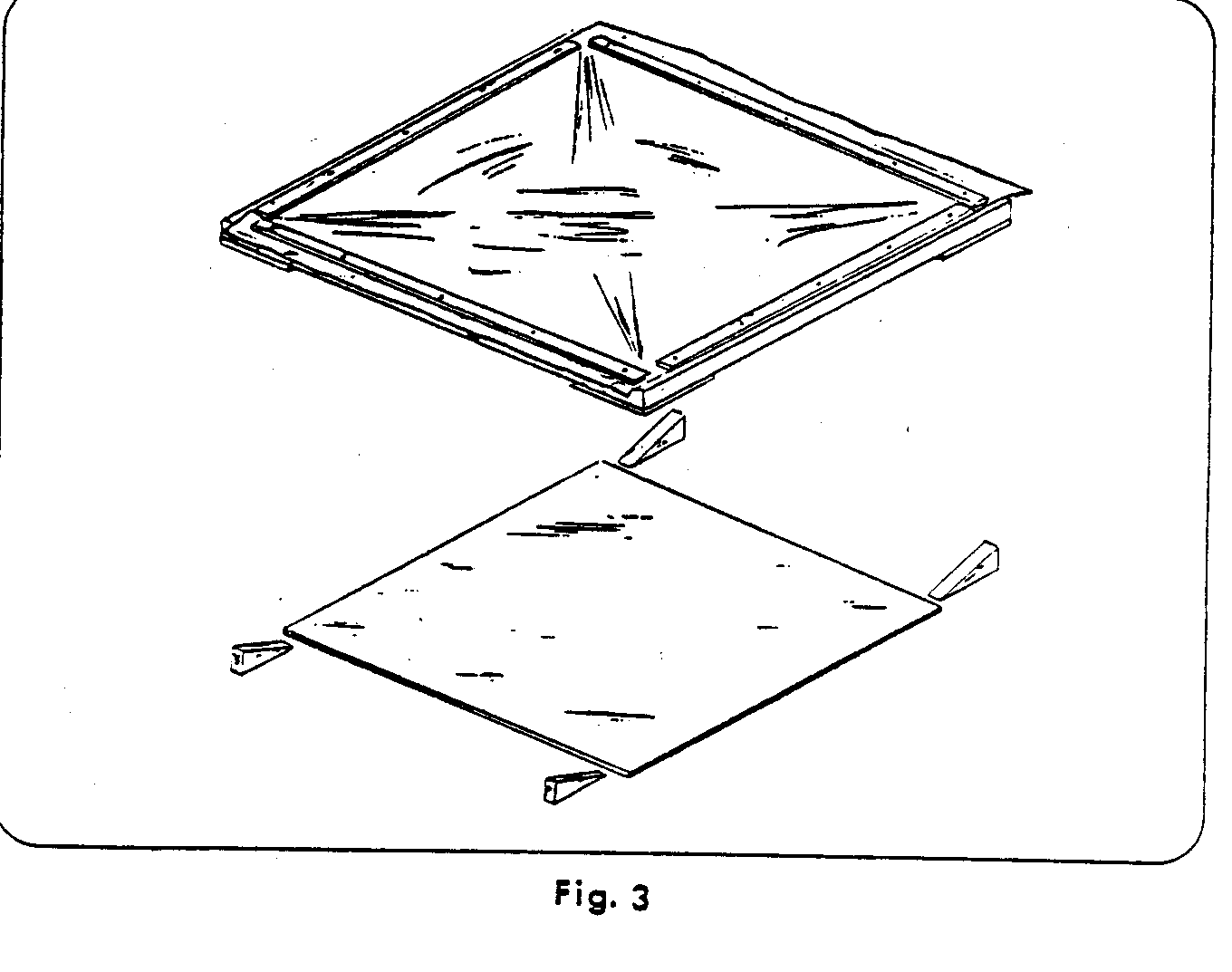
D. Place the frame over the glued surface of the Masonite on the four (4) wedges with the aluminized side down. Pull the wedges out until the center of the Mylar hangs a few cm. above the center of the glue-covered Masonite. (See Fig. 3)
E. Apply the Mylar to the Masonite with a stiff dry squeegee, working from the center outward (see Fig. 3A), using
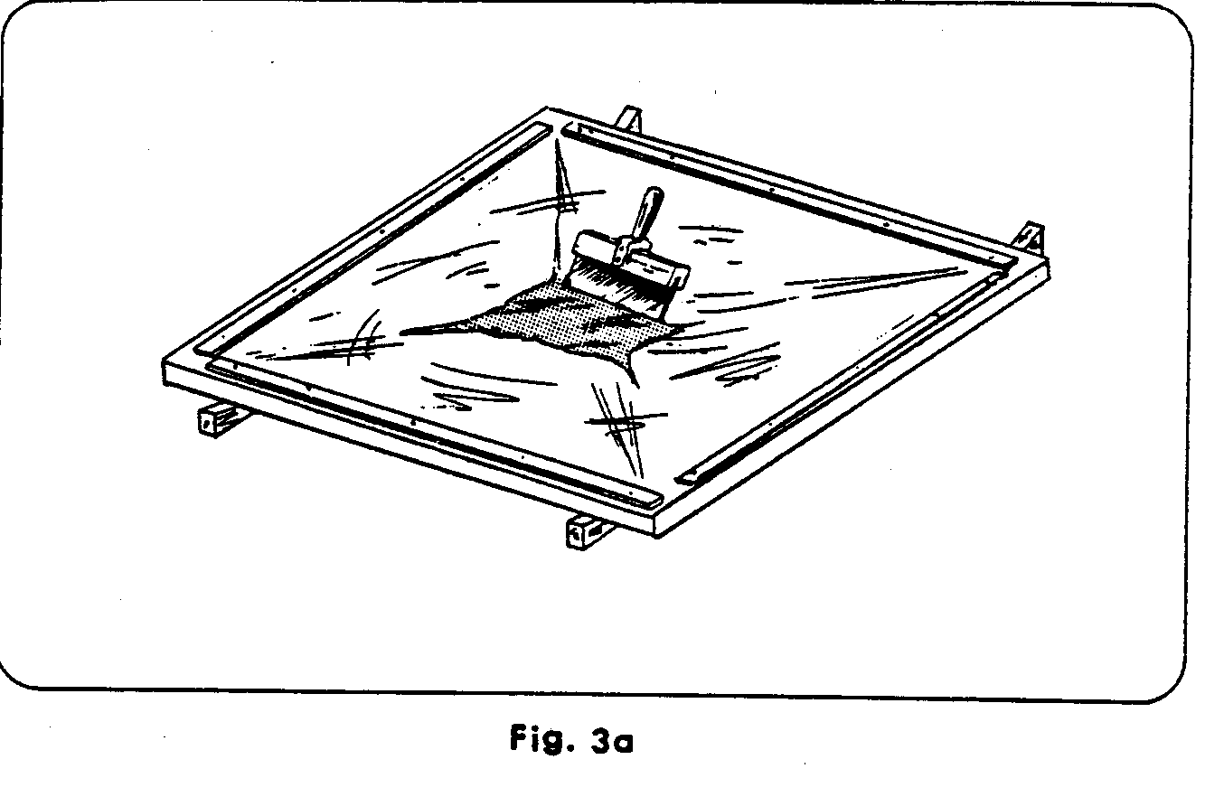
short, firm strokes. Try to keep the Mylar quite taut between the glued area and the frame so that the Mylar does not touch the Masonite until the squeegee strokes pull it down. If the Mylar rips from the frame and falls on the Masonite, it will form many ridges and bubbles. In any case, ridges and bubbles are sure to form and the Mylar must be lifted and reapplied in the wrinkled regions.
Try the following procedure: spread the Mylar, starting from the center as far toward the edges as possible, using the tension suppled by the frame. Gradually lower the edges, let the force of the strokes rip the Mylar from the frame. If serious ridges or bubbles appear far from the edge, free the Mylar from that region either by lifting the frame or by ripping the Mylar from part of the frame and pulling it upward and outward by hand. Don't worry about the four corners as they will be sawed off anyway.
Remember that applying the Mylar is the most difficult part of building the solar cooker; it takes some practice and patience and you are fortunate if the first few efforts are successful.
F. Trim the overhanging edges of the Mylar with a razor blade.
G. With a needle or the razor blade, puncture all the air bubbles and press them down; small air bubbles fixed in this way are hardly noticeable afterward.
H. Clean the surface of any traces of glue with a damp cloth.
I. Allow one day for the glue to dry.
- Cutting out the rings. (see Fig. 4)
A. Locate the geometric center of the Masonite by marking where the two diagonals meet. Be careful not to tear the Mylar.
B. Cut out the rings with a coping saw or a jigsaw if one is available, using the holes in the supplied template as radii. It may be convenient to nail down the center and rotate the whole sheet, keeping the saw stationary. This may save the trouble of drawing out the rings.
C. From the inner ring cut out a section with a width at the outer edge of .5 cm.
D. From the next most inner ring cut out a section with a width at the outer edge of 2.8 cm.
- Preparing the legs.
A. Cut Out the two legs, using the template enclosed. (You may wish to copy the template onto sheet metal.) Use 2 cm. x 12 cm. x 150 cm. pieces of wood. At the center notch one leg from above and one from below as shown on the template, so that their edges are flush. B. Fit the two pieces together at the 2 cm. center slots. Cut a wooden tie bar about 40 cm. long (with 45[degrees] ends if you would like) and nail or screw it to the backs of legs so that the legs form an angle of exactly 90[degrees]. (See Fig. 5)
- Bending the rings into place and mounting them onto the legs. (See Fig. 6)
A. Place the inner ring (#1) on the frame and squeeze it closed at one of the cross pieces, nailing both ends to the same leg. Nail down the ring at the other places where it crosses the frame as well, using 5 cm. aluminum nails (or screws).
B. Do the same thing with ring #2; the ring should fit easily into the slots in the legs.
C. Saw through ring #3 if you haven't already. Work it into the slots on the frame and ovelap it somewhere between two crosspieces. It should overlap 8.8 cm. on the outer edge and 6 cm. on the inner edge. Clamp it into place. D. Do the same with the outer ring (#4). It should overlap 19.8 cm. on the outer edge and 14.5 cm. on the inner edge.
E. Place a light source about five meters from the cooker and point the cooker at this source. Looking at the cooker from about a meter directly in front, adjust rings #3 and #4 until the reflection is even all the way around all four rings. If the rings and legs have been properly cut, very little adjustment would be necessary.
F. When you are satisfied, there are two ways to fasten the outer two rings in place:
- Close the rings by bolting or riveting them through the Masonite where they overlap, at two or three locations not lying on the same radius. Then nail them to the frame; or:
- Cut a wider slat in one of the crosspieces and overlap the rings on top of this crosspiece. Nail through the two layers of Masonite. This latter method is less durable and produces a less satisfactory shape of the outer rings.
G. Clean the rings with a damp cloth and paint or tape the expanded edges of the rings to prevent weathering underneath the Mylar.
- Providing a cooking vessel support.
Any support will do as long as the pot is placed so that the pot rests in the bright focal region about one meter from the cooker. A separate tripod is one possibility. Another design is as follows:
A. Drill a 6 mm. hole about 2 cm. from one end of a 50 cm. x 18 mm. x 3 mm. strip of hot-rolled iron. Using a cold chisel, make radial indentations around the hole on one side.
B. Bend the strip into a circle of the desired dimeter (the right size to hold a cooking vessel), with the chisel marks on the outside of the ring formed. A round wooden form will help.
C. Drill a 6 mm. hole in the other end of the strip at the place where they overlap to form the closed ring. Drill another hole directly opposite this one.
D. Drill a 6 mm. hole 1 cm. from each end of a 40 cm. x 18 mm. x 3 mm. strip of hot-rolled iron. Score around earch hole with the chisel. Place this strip in a vise so that the middle 10 cm. are securely held. Grip the strip about 4 cm. from the vise with a wrench with adjustable jaws; give a quarter turn so that the end is horizontal. Repeat this with the other end. (Fig. 7)
E. Bend the horizcntal ends to form a "U" with the chisel marks on the inside and the ends about as far apart as the width of the ring formed in step B. (Change the dimensions in step D if necessary.) Drill a 6 mm. hole in the center of the bottom part of the "U".
F. Cut a 2. 5 cm.-deep slot diagonally into one end of the support rod (25 mm. x 25 mm. x 80 cm.), a little narrower than 3 mm. Flatten the edges of the rod and drill a 6 mm. hole across the slot. (Fig. 8)
G. Secure the metal "U" in the slot with a 3 cm. x 6 mm. stove bolt. Mount the metal ring between the ends of the "U" with two 25 mm. x 6 mm. stove bolts and fitting wing nuts, with lock washers between the ring and the "U" if you wish.
H. Cut a short triangular wooden block to fit snugly into position at the vertex of the two legs. Nail it in place.
I. Take the cooker outdoors. Rest the support rod in place in the vertex of the two legs, place a pot in the metal ring and aim the cooker at the sun. Change the distance which the support rod projects until the brightest part of the focal spot is on the bottom of the pot. Mark the position of the support rod.
J. Chisel off the upper edge of the support rod at its lower end and drill a hole down through it, the vertex of the legs, and the triangular wooden block. Bolt the rod in place with an 11 cm. stove bolt with fitting wing nut. (Fig. 9)
- Providing an adjustable brace.
Brace the cooker in a position facing directly into the sun so that the bright focal spot is on the bottom of the cooking vessel. It must be adjusted about every twenty minutes as the sun moves. The angle adjustment can be done with notched pieces of wood propped against the tie bar. A better system, however, is the leg assembly shown in Fig. 9. This will be more secure. It requires s strip of iron, two 4 cm. bolts, a longer bolt, and two pieces of wood, one about twice as long as the other. Their exact length will depend on your latitude and the time of day the cooker is commonly used.
Anchor the legs firmly to keep the cooker from being blown over by the wind.
Aluminized Mylar and epoxy may have to be imported. Addreses where they can be obtained in the United States are:
.0005-inch chrome metalized Mylar, 160 cm. wide, $1.00 U. S. per yard:
Coating Products, Inc. 101 West Forest Avenue Englewood, New Jersey 07631 U.S.A.
Epoxy: Astro Special 1100, 8 pounds per gallon at $1.30 U.S. per pound.
Hardener: Astro Special 2950, 8 pounds per gallon at $1.65 U.S. per pound.
Astro Chemical Company, Inc. 1205 Godfrey Lane Schenectady, New York 12309 U.S.A.
Figure 10. Using the Cooker
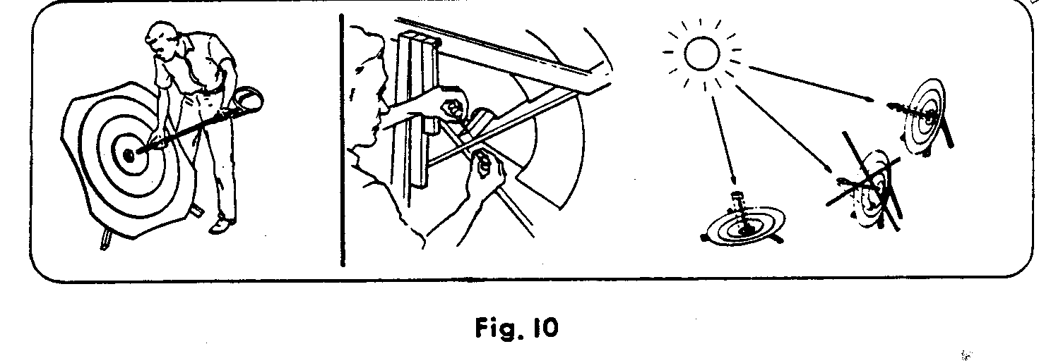
- Install the support rod in place in the vertex of the two legs. Aim the cooker at the sun.
- Adjust the support rod so that the brightest part of the focal spot hits the bottom of a pot placed in the support. Drill a hole through the support rod, the vertex of the legs and the triangular wooden block. Bolt the rod in place.
- Brace the cooker so that it faces directly into the sun, with the bright focal spot on the bottom of the cooking vessel. The shadow of the cooking vessel will be in the center of the cooker. If the shadow is outside the center, the cooker is not facing direatly into the sun.
- Adjust the cooker every 30 minutes as the sun moves.
SOLAR COOKER LEG TEMPLATE
This template is to be used to make a 152-cm (5-toof) template for the legs of the VITA Solar Cooker. See Paragraph 6A and Fig. 5,
page 11. The complete template is AB (88.5cm) plus BC (63.5cm). To make the template, cut out the four pieces shown and

string or a straightedge to be sure ACB is a straight line.
SPECIAL NOTE ON THE VITA SOLAR COOKER MANUAL
Although we are sending you the VITA Solar Cooker Manuals, we feel it is important to point out some limitations in its use. These are partially covered on pages 1 and 2 of the manual and are repeated here for emphasis.
The VITA Solar Cooker is not useful for day by day cooking in most circumstances. To be useful requires understanding of the following limitations.
1. The cooker is probably not practical where the average of the hours of sunlight is under 2000 hours per year.
2. The cooker is not useful for cooking meals in early morning or late afternoon.
3. The cooker must be frequently shifted in position during use (once every 10 minutes or so) to take advantage of the sun's position.
4. Making a good contact between the Mylar film and its backing is tricky and requires practice. One will probably ruin a few cookers in the process of learning how to make this seal. For this reason it is important to order enough materials for a few cookers in hopes of getting one good one. After this techniques mastered, there is little material spoilage.
5. It requires the development of some technique to cook with the cooker. This process can be developed by a trial and error procedure. So experienced people have compared this learning process to be about as difficult as learning how to knit.
6. In many areas of the world the cooker cannot compete economically with existing methods of cooking. For example, one should calculate how long it would take to recover the initial investment in the cooker from the savings on fuel that come about because of its use.
7. To properly introduce the cooker to a local populace requires careful thought and painstaking effort. Those experienced in the process of introduction should be consulted to see how it can best be put to use in the given culture. Aside from local taboos (religious, social traditional, etc.) there will be the very formidable barrier of resistance to change. People will be quick to point out the difference in taste (whether there is one or not) the longer or shorter cooking times, the space required to store the heater, the need for being outside while cooking, etc.
Nevertheless, the cooker does represent a method of putting the free-for-the-asking energy of the sun to work, and if this can be accomplished economically in your community, it will bring the further advantages of a more smoke-free atmosphere, less real danger of open flame, and an opportunity to prove to the local people that a new method can sometimes prove to be an advantage over old procedures, thereby reducing that major obstacle to progress, "resistance to change."
If you decide to go ahead with the construction and introduction of the cooker with full knowledge of its problems and limitations, and you think through a plan of introduction, you could well make a real contribution to the people of your community. Do not, however, expect to quickly build a cooker properly the first time and be adequately cooking with it on your first try. Good luck in your efforts.
SOLAR COOKER ADDENDUM
VITA has been able to locate a substitute for one of the less easily obtainable materials (aluminized Mylar film) called for in the solar cooker manual. That substitute is aluminum foil. The problem of using aluminum foil, however, is that conventional attempts to fasten the foil yield discouraging results (the foil wrinkles easily) and commonly available cements and/or glues will not hold the foil to the cooker surface adequately. The following procedure, then, will help you over the difficulties of applying aluminum foil successfully:
- Remove the foil from the roll with a minimum of wrinkling;
- Apply the cement in the same manner mentioned in the manual.(*) However, apply the cement to not more than one foot of the cooker surface at any one time;
- Gently lay on appropriate length of foil down on the cemented surface while anchoring one end of the foil with one hand to prevent it from slipping;
- Smooth the foil with your right hand, keeping that hand wet by dunking it in water (if your right hand becomes dry while rubbing the foil, it will tend to bounce along the foil, causing ridges);
- The foil is then rolled with a roller. Do not press hard on the roller;
- Repeat the above process on successive sections of the cooker surface until the cooker is covered. If too many wrinkles appear on the foil, remove that section and try again.
* One substitute for the epoxy cement shown in the manual is "waterglass" (sodium or potassium silicate). A fairly strong solution of water-glass when applied as a substitute to the epoxy cement will harden within 20 minutes when placed in direct sunlight. Note that "water-glass" will dry most rapidly in dry climates, so where extended drying periods are needed, do the gluing in a cool damp room. The water in this mixture will tend to soak through the masonite; therefore it is suggested that you place the masonite disk on a flat surface to prevent warping. And if the glue is too thin, it can be made more pasty by mixing in a smooth filler powder such as red lead or kaolin, without affecting its hardness or stregth.
Material submitted by:
Mr. Terance Maaske Scottsdale, Arizona
IF YOU NEED MORE manual or on other technical matters, VITA (Volunteers in Technical Assistance, Inc.) can send it to you. If you have specific questions, VITA can put you in contact with an expert who can answer them.
VITA is an international association of scientists, engineers, technicians, businessmen, educators and others who volunteer their spare time to consult on questions from persons in developing areas.
Simply send your request to:
Volunteers In Technical Assistance 1600 Wilson Boulevard. Suite 500 Post Office Box 12438 Arlington. Virginia 22209-8438 USA
To help the VITA Volunteer who answers your request, you should:
- Be quantitative -- give measurements, costs, materials available, sketches when possible.
- Describe the best solution, if any, found nearby and any limiting cultural factors.
- Indicate a deadline for action. You will hear directly from the VITA Volunteer; keep in contact with him; inform the VITA Office if correspondence stops.
ABOUT VITA
Volunteers in Technical Assistance (VITA) is a private, nonprofit, international development organization. Started in 1959 by a group of concerned scientists and engineers, VITA maintains an extensive documentation center and worldwide roster of volunteer technical experts. VITA makes available to individuals and organizations in developing countries a variety of information and technical resources aimed at fostering self-sufficiency--needs assessment and program development support; by-mail and on-site consulting services; information systems training. It publishes a variety of technical manuals and manuals.