A VITA PUBLICATION
VITA 1600 Wilson Boulevard, Suite 500 Arlington, Virginia 22209 USA Tel: 703/276-1800 . Fax: 703/243-1865 Internet: pr-info@vita.org
ACKNOWLEDGEMENTS
Production of Six Simple Pumps has required the advice and expertise of many VITA Volunteers. VITA is indebted to them, not only for the original designs, but also for their expert guidance during the preparation of the manual. Special thanks go to:
Derek W. Adams, technical manager of engineering and R&D for Daystrom Ltd., Gloucester, U.K.; Stephen Bernath, consultant in forest hydrology and watershed management; Leonard G. Doak, professional engineer and literacy consultant; Dale Fritz, expert in pumps, wells, and farm equipment; V. Geethaguru, research technologist at the Shri AMMA Murugappa Chettiar Research Centre, Madras, India; William Kennedy, member of the faculty of engineering mechanics at the Open University, Milton Keynes, U.K.; Dr. Richard G. Koegel, Research Agricultural Engineer with the U.S. Dairy Forage Research Center in Madison, Wisconsin; Jerry Lundquist, technical writer and editor; Loren Sadler, senior design engineer for the Sperry New Holland Co.; Dr. Clifford L. Sayre, Jr., professor of mechanical engineering at the University of Maryland; Dr. Charles D. Spangler, sanitary engineering consultant to the World Bank, WHO, USAID, and others; and Dr. Yaron M. Sternberg, professor of civil engineering and director of the International Rural Water Resources Laboratory at the University of Maryland.
Christopher Schmidt, free-lance artist, provided the drawings, and Julie Badger of the VITA staff did typesetting and layout. Other staff assistants were Gregory A. James and Robert Reining.
Publication of Six Simple Pumps was made possible by a grant from Dresser Industries, Inc., a leading manufacturer of pumps and pumping apparatus. With its own commercial products unaffordable by many people in developing countries, Dresser supports VITA in this effort to help those same people attain a reliable supply of water.
Margaret Crouch, VITA Publications Volunteers in Technical Assistance Arlington, Virginia December 1982
TABLE OF CONTENTS
INTRODUCTION
-
DIAPHRAGM PUMP (Irrigation)
-
PITCHER PUMP (Irrigation or potable water)
-
SPANGLER PUMPS (Potable water or irrigation)
-
INERTIA PUMP (Irrigation)
-
ANIMAL DRIVEN CHAIN PUMP (Irrigation)
-
ARCHIMEDES SCREW (Irrigation)
CONVERSION TABLES
REFERENCES AND RESOURCES
APPENDIX I - DECISION MAKING WORKSHEET
II - RECORD KEEPING WORKSHEET
III - WOODEN BEARING BLOCK FABRICATION
INTRODUCTION
Over the years VITA has made available designs for a wide variety of manually operated pumps, developed or modified primarily by VITA Volunteers for projects in the field. The designs respond to local conditions--a pump with wooden parts for Vietnam where little metal was available; another based on polyvinyl chloride (PVC) pipe; still others adapted from tried and true designs, but with added efficiency or ease of construction.
VITA has compiled some half dozen of these designs into this manual. The collection snows a range of options for simple pumps that are relatively cheap and easy to build and maintain with local skills and materials. They present viable alternatives to more expensive pumps requiring costly fossil fuels for operation. Several would also serve well as the basis for small manufacturing enterprises.
Because they must be primed or otherwise cannot be sealed, most of the pumps and water-lifting devices presented here are primarily useful for irrigation purposes. The Spangler pumps, and the pitcher pump in certain applications, however, can be used effectively in sanitary wells for potable water supply systems.
For health and safety reasons, the well to be used with the pumps should be covered if possible. Small-bore sanitary wells should be sealed with cement or stone- or brick-work to prevent contamination of the water supply. Larger wells may be covered with sturdy platforms. The well cover provides a base for attaching the pump-stand, and helps prevent entrance into the well of debris that might damage the pump or cause excessive wear on the moving parts.
The ground around the well should be sloped away from the well opening to allow excess water to run off. This helps prevent the seepage of polluted water back into the well. It also helps prevent the buildup of mud anti stagnant pools that are prime breeding grounds for hookworm, mosquitoes, and other pests.
But this is a pump book, not a wells manual. The editors do presume a level of experience--or access to expertise--with wells. For further information on building and operating water wells, readers are referred in the Resources section to several excellent books on the subject. And for the proper protection of drinking water wells, check with the nearest sanitary inspector of the Ministry of Health.
Complete instructions for building each pump are included in the manual, with detailed drawings to guide construction. Operating and maintenance directions are also given. Efficiency comparisons enable the user to choose the best design for a particular situation.
Readers who may be using this manual as part of an irrigation or water supply project are urged to contact VITA for needed technical assistance. The decision making guide in Appendix I will help frame questions and focus project considerations. VITA can also provide technical. and management assistance to those who may be interested in manufacturing the pumps.
Table of Uses and Costs
Pump Deep Shallow Flow: Est. cost: type well well gal/min. 1981 US$
1. Diaphragm
to 25 ft. 10 to 30 $10 to $20
2. Pitcher
15 ft. 8 to 10 $20 to $40
- Spangler 50[plus] ft. to 20 ft. 5 to 15 $20
4. Inertia
12 to 24 ft. 20 to 70 $10 to $20
5. Animal
maximum 100 to 150 $50 to $100 Driven 20 ft. plus, de- Chain pending on availabil- ity of parts
- Archi-
- 1 to 2 ft. 50 to 150 $10 to $50 medes Screw
DIAPHRAGM PUMP
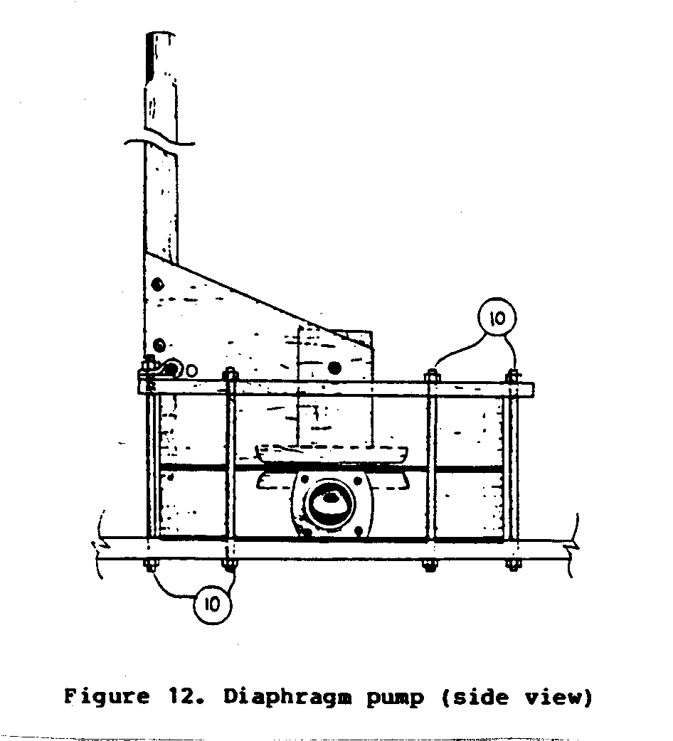
This hand-operated pump <see figure 1-5> was designed for use in Vietnam in the
early 1960s. It is made primarily of wood and rubber, plus metal fasteners, washers, and bushings at two wear points. It consists of a pumping chamber that is a watertight wooden box fitted with two rubber flap valves. A diaphragm made from inner tube rubber forms the top of the lower pumping chamber. A vertical pump handle is attached to the center of the diaphragm. Moving the pump handle increases or decreases the volume of the pumping chamber. It is the change of volume in conjunction with the two flap valves that forces water through the pump.
Two or three liters of water can be pumped a vertical distance of three to four meters at each stroke. If the pump is made smaller, it will pump a smaller amount of water a greater distance. If it is made larger, it will pump a larger amount of water a shorter distance.
The pump can be operated by one or two people, and can be adapted for use with animal or wind power. Bamboo piping or other low cost piping can be used with the pump to deliver water economically for considerable distances. Two or more pumps can be used side-by-side to move more water per stroke, or end-to-end to move water farther.
This pump has the following advantages:
1) It is extremely simple, without any close-fitting or machined parts. It can be built and repaired with skills and materials found in the average village.
2) Unlike hand irrigation with buckets, the worker remains stationary while only the water moves. In using pole and buckets, the worker must raise his entire body weight, plus that of the pole and buckets. This is nearly twice the weight of the water. In addition, the worker with buckets must make a return trip. The pole and bucket system wastes a great deal of human energy.
Dr. Richard G. Koegel, the primary designer of this plan, is with the U.S. Dairy Forage Research Center at Madison, Wisconsin. A VITA Volunteer for many years, Dr. Koegel has long experience in Asia and Africa where he designed, built, and tested many technologies disseminated through VITA.
MATERIALS AND TOOLS
MATERIALS:
Part Description Size Quantity Number
1 Handle 2" by 2" by 36", hardwood 1
1a Handle arm 1" by 6" by 8-1/2", hardwood 2
1b Bolts, arm to pump handle 3/8" dia. by 4", machine 2 bolts with nuts and flat washers
1c Pivot rod for handle 1/2" dia. by 8" steel rod 1 or G.I. pipe
1d Pivot rod mounting clamps Approx. 1/16" by 1" by 4" 2 sheet metal strip
2 Top plate 1" by 14" by 14", hardwood 1
3 Upper and lower chamber 1" by 4" by 10", hardwood 4 frame parts
3a Screws, upper and lower Approx. 1/4" by 2" lag 12 frame bolts or wood screws
4 Diaphragm Approx. 1/16" by 12" by 12" 1 inner tube rubber
4a Diaphragm supports 1" by 7" by 7", hardwood 2
4b Diaphragm support Approx. 1/4" by 3-1/2" 12 fastening screws lag bolts or wood screws
4c Diaphragm support arm 2" by 4" by 6", hardwood 1
4d Diaphragm support arm 3/8" dia. by 5" machine 1 connector bolt, nut and flat washer
5 Upper and lower frame parts 1" by 4" by 12", hardwood 4
5a Same as part 3a Same as part 3a 12
6 Outlet check valve Approx. 1/16" by 2-1/2" by 1 2-3/4" inner tube rubber
6a Outlet check valve Approx. 1/16" by 2-1/2" 1 reinforcement dia. sheet metal disk
6b Outlet valve reinforcement 1/4" dia. by 1" machine 1 bolt bolt, nut, and flat washer
Part Description Size Quantity Number
6c Outlet check valve 3/4" long flat head nails 3 fastener
6d Outlet valve gasket Approx. 1/16" by 4" by 6" 1 inner tube rubber
6e Spacer block 2" by 4" by 6", hardwood 1
6f Outlet valve gasket Approx. 1/16" by 4" by 6" 1 inner tube rubber
6g Outlet flange 2" inner dia. pipe flange 1
6h Outlet valve assembly 3/8" dia. by 4-1/2" machine 4 bolts, nuts, and flat bolts, nuts, and flat washers washers
7 Inlet check valve Approx. 1/16" by 2-1/2" by 1 3-3/4" inner tube rubber
7a Inlet check valve Approx. 1/16" by 2-1/2" 1 reinforcement dia. steel disk
7b Inlet valve reinforcement 1/4" dia. by 1" machine 1 bolt bolt, nut, and flat washer
7c Inlet check valve fasteners 3/4" long flathead nails 3
7d Inlet valve gasket Approx. 1/16" by 4" by 6", 1 inner tube rubber
7e Inlet flange 2" inner dia. pipe flange 1
7f Inlet valve assembly 3/8" dia. by 1-1/2" machine 4 bolts bolts, nuts, and flat washers
8 Bottom gasket Approx. 1/16" by 12" by 12" 1 inner tube rubber
9 Baseboard 2" by 14" by 48", hardwood 1
10 Unit assembly bolts 3/8" dia. by 12" machine 12 bolts, nuts, and flat washers (24)
Waterproof glue, gum, or pitch--about 2 ounces for sealing joints
Notes: 1) When lifting water for more than three or four meters, it may be necessary to use more layers of rubber or to use thicker rubber in the diaphragm, Part 4. 2) The two metal pipe flanges, Parts 6g and 7e, should be bought before drilling the two 2-inch holes in the lower chamber frame parts, Part 3. The size of these flanges, and the holes for the mounting bolts may require changes in the two bottom frame parts. If such pipe flanges are not available, you can make substitutes by welding a 2-inch pipe coupling to a 1/4-inch steel plate with a 2-inch hole cut in it. 3) In making this pump, you can substitute narrower boards that are adequately cross-braced for planks of 12- and 14-inch widths.
TOOLS:
Drill for metal: 3/8", or any means of cutting 3/8" hole in sheet metal Wood drills: 1/4", 3/8", and 1/2", or metric equivalents Pliers or suitable adjustable wrench Wood chisel or tool for making 2" hole in hardwood Metal saw or hacksaw Wood rasp or file Screwdriver Tin snips Wood saw File
CONSTRUCTION
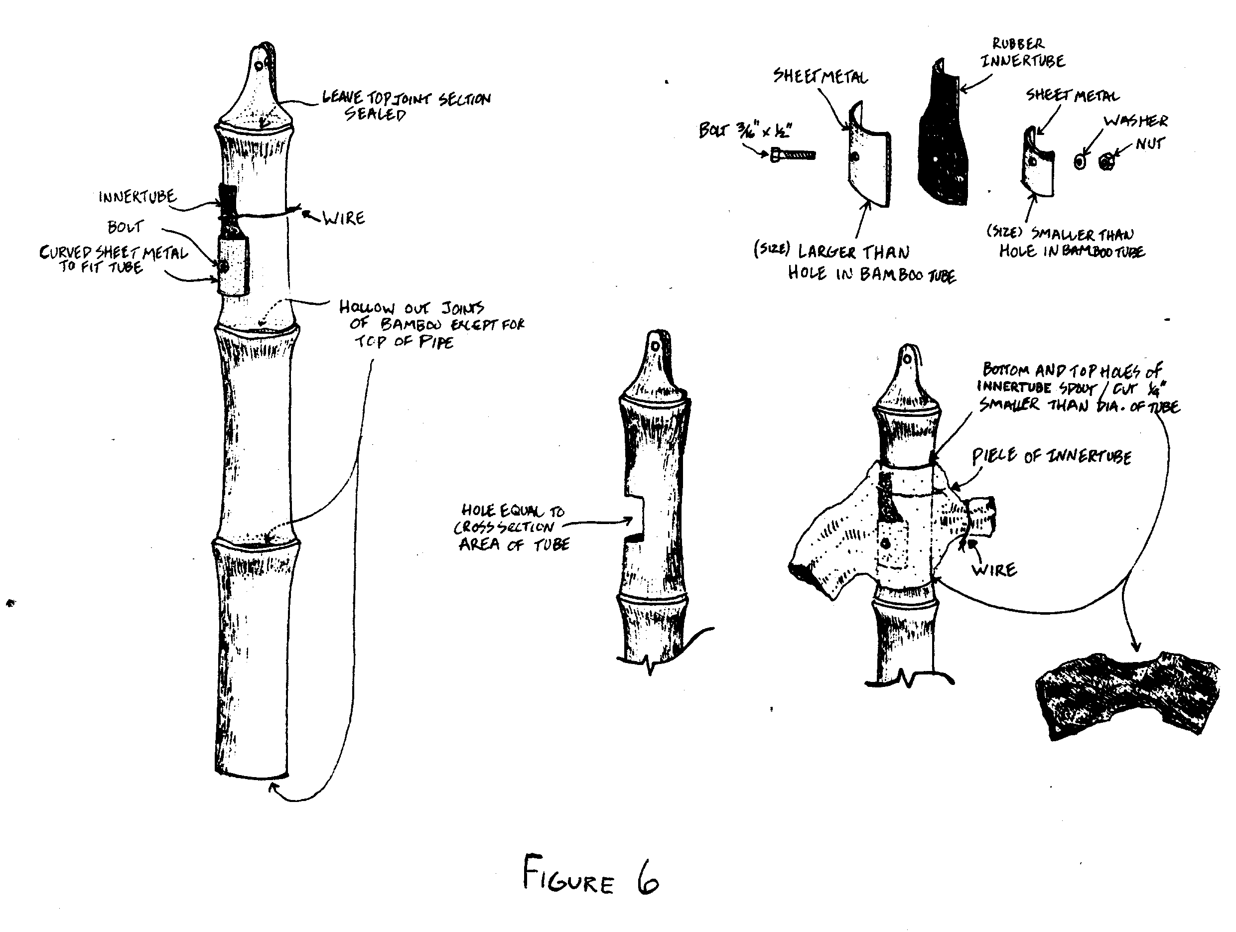
Handle, Part 1, Figure 6
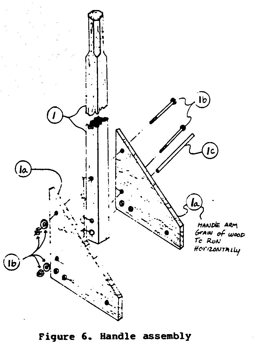
Smooth handle along the top 8" to 10" to make it easier to grip with your hands. Bore two 3/8"-diameter holes, one 2" from the bottom and one 5" from the bottom. Bore a 1/2" hole 1" from the bottom and from the same side as the other two holes.
Handle Arm, Part 1a, Figures 6, 7

Bore a 3/8"-diameter hole 1" from the pointed end of the 6"-long side, and another 3/8" hole 3" down from that one. Both holes should be 1" from the edge. Bore a 1/2" hole 1" from the 6" side and 1" from the 8" side. Drill a second 1/2" hole 1" from the first and 1" in from the 8" edge. Bore a 3/8" hole 2" from the other end of the 8" side and 1" in from the edge. The two handle arms should be identical.
Pivot Rod Mounting Clamps, Part 1d
These two clamps are made from approximately 16-gauge sheet metal. Wrap each one over the pivot rod for handle, Part 1c, and drill a 3/8" hole through both thicknesses (See Figure 9).
(These clamps will later be mounted to the top plate, Part 2, by unit assembly bolts, Part 10).
Diaphragm, Part 4
Cut the diaphragm, Part 4, from inner tube material. Center the two diaphragm supports, Part 4a, over the diaphragm. Drill the 12 holes for the diaphragm support fastening screws, Part 4b. Round the edges of the diaphragm supports that touch the diaphragm. Screw together the two diaphragm supports with the diaphragm between them. Saw out the diaphragm support arm, Part 4c, so the wood grain runs vertically in the material (See Figure 8).
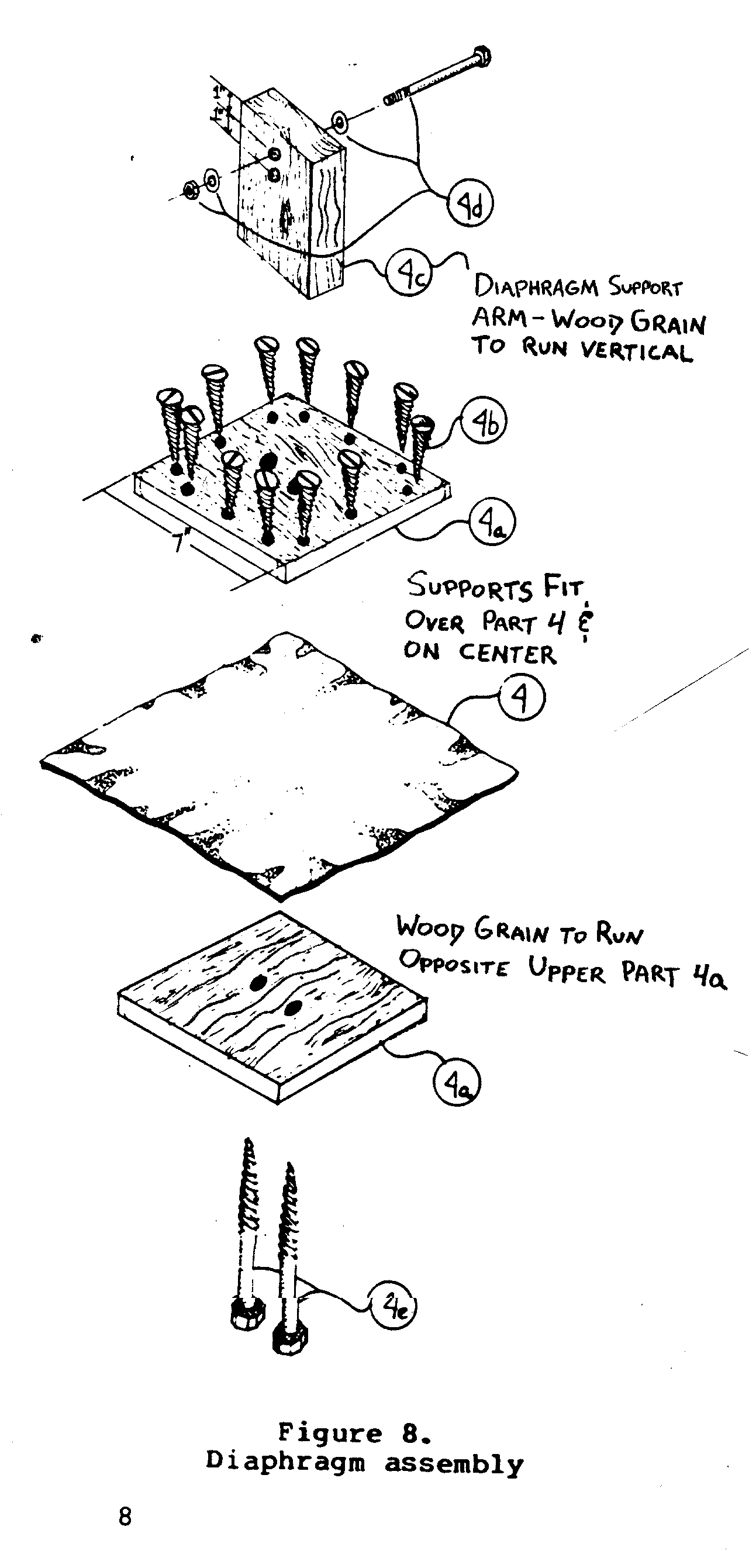
Bore two 3/8"-diameter holes in the support arm, one 1" from the top and the other 2" from the top, each 2" from the edge. (The lower hole is needed later.)
Fasten the support arm, Part 4c, to both supports with the two 1/4" by 3-1/2" wood screws or lag bolts, Part 4e. NOTE: The pump has been built and used with screws joining the two diaphragm supports. It will be easier to replace the diaphragm if bolts are used to join the diaphragm supports, and to join the assembly to the diaphragm support arm.
The diaphragm assembly is now ready to be joined to the pump handle arm by a 3/8" by 5" machine bolt, two flat washers, and a nut. The diaphragm support arm should pivot easily on the bolt.
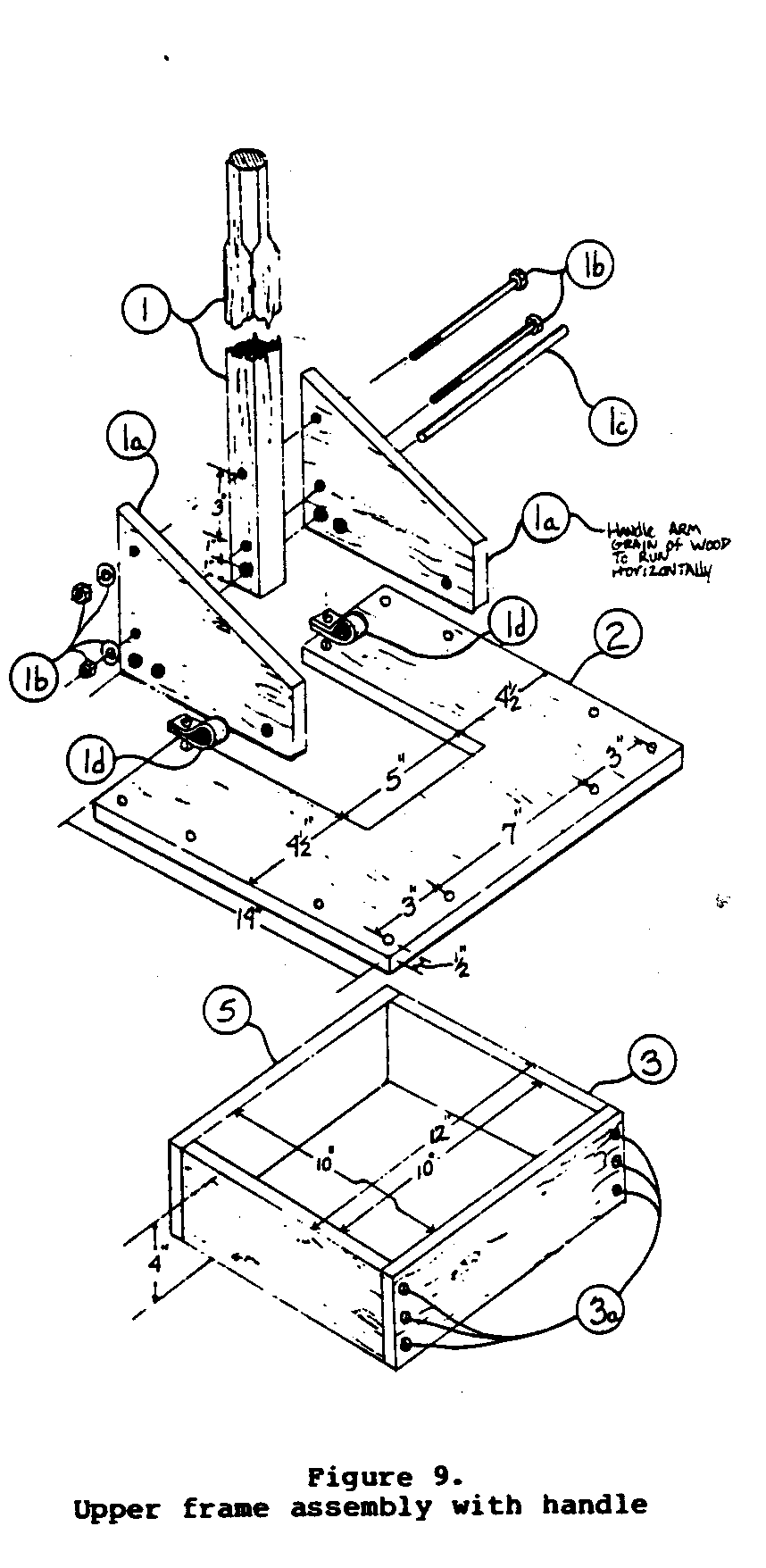
Frame Assemblies, Figures 9, 10

The top and bottom chamber frames, Parts 3 and 5, must be cut and assembled to be as flat and square as possible. In making the top frame assembly--two of Part 3 and two of Part 5--the bottom must be very flat and square because this is used to hold the diaphragm in place.
Top Frame, Figures 9, 10
Two top frame pieces, Part 3, and two top frame pieces, Part 5, should be assembled using three 1/4" by 2" lag bolts at each joint (Part 3a). Before assembling, make sure that the ends to be joined are smooth and flat. Use glue, gum, or pitch in the joints.
Bottom Frame and Valve Assemblies, Figure 11:
The two metal pipe flanges, Parts 6g and 7e, should be sawed so that the two straight edges are parallel and 3-3/4" apart. Bore 3/8" holes in each, as shown in Figure 11.
Cut parts 6, 6a, 7, and 7a from rubber inner tube material to the sizes shown in the parts list. Round the bottom edges of parts 6 and 7.
Join the outlet check valve and the outlet valve reinforcement, Parts 6 and 6a, with the outlet valve reinforcement bolt, washer, and nut, part 6b. Join the inlet check valve and the inlet check valve reinforcement, Parts 7 and 7a, with the inlet valve reinforcement nut, washer, and bolt, Part 7b.
Bore a 2"-dia. hole in the center of each bottom frame part, Part 3. Using the two metal pipe flanges as guides, one to each Part 3, center the flange on the 2" hole, then mark and drill the four 3/8" holes around the 2" hole on each piece.
Cut one outlet valve gasket, Part 6d, and one inlet valve gasket, Part 7d, from inner tube rubber to the dimensions shown in the parts list. Cut a 2" hole in Part 7d and a 3" square hole in Part 6d, as shown. Cut the second outlet valve gasket, Part 6f. Cut a 2" hole in the second gasket.
Cut a spacer block, Part 6e, to the size shown in the parts list. Cut a 3"-square hole in its center. Bore four 3/8"-dia. holes in the spacer block to line up with the four holes in the outlet flange.
Now assemble the bottom frame in the same way as you did the top frame. Nail the outlet check valve on the outside of the outlet valve hole with the outlet check valve fasteners, Part 6c. Be sure the outlet check valve reinforcement is on the side away from the bottom frame. Now do the same for the inlet check valve, but this time have the reinforcement on the inside of the bottom frame (See Figure 11).
Assemble the outlet valve gasket, Part 6d, the spacer block, Part 6e, the second outlet valve gasket, Part 6f, and the outlet flange, Part 6a, on the outlet side of the bottom frame, using the 3/8" by 4-1/2' machine bolts, nuts, and flat washers. Use glue, gum, or pitch to seal these parts.
Assemble the inlet valve gasket, Part 7d, and the inlet flange, Part 7e, on the inlet side of the bottom frame, using the 3/8" by 1-1/2" machine bolts, nuts, and washers, Part 7f. Use glue, gum, or pitch to seal these parts.
Final assembly of the pump will be simplified if you make a pattern for boring holes for the unit assembly bolts, Part 10. The pattern should be a square of thin stiff material 2" larger than the top and bottom frame parts. (For this size pump, make the pattern 14" on each side.) Mark a line 1/2" in from each edge. Using a nail, make a hole through the pattern 1/2" in from each corner. Then make additional holes 3" from each corner hole, each 1/2" from the edge of the pattern. Use this pattern for marking the places to drill holes through the top plate, Part 2, and the baseboard, Part 9.
The holes in the baseboard should be drilled 18-1/2" from the end and 1/2" in from the two edges, using the pattern to mark the position of the holes.
Assemble the pump by putting a 3/8" by 12" machine bolt and washer, Part 10, through each of the four corner holes in the baseboard, from the bottom. Put the bottom gasket, Part 8, in place. Using glue, gum, or pitch between each surface, put the bottom frame section, the diaphragm, Part 4, and the upper frame section in place. Fit the top plate, Part 2, over the four bolts (See Figure 12).
Loosely fit a flat washer and a nut, Part 10, on each of the four bolts. Complete the assembly by inserting the remaining bolts with washers through the complete pump. Put a washer on top of each bolt, and loosely fit nuts on them.
Tighten each of the nuts with your fingers, starting in one corner and tightening each in turn. Then tighten all of the nuts with a wrench, one at a time, with gradual even pressure. Do not tighten one nut as tight as it will go, and then another. Tighten each one a little bit at a time.
PRECAUTIONS
Woodgrain
The grain of the wood must be in a specified direction on certain parts of this pump:
- Top plate, Part 2: the grain in this wood should run in the same direction as the slot that is 5" wide and 11" long.
- Diaphragm supports, Part 4a: when these two parts are assembled on the diaphragm, the grain in one piece should be 90[degrees] from the grain in the other.
- Diaphragm support arm, Part 4c: the grain in this part should run from one 4"-wide end to the other.
- Spacer block, Part 6e: the grain here should run from one 4"-wide end to the other.
- Baseboard, Part 9: the grain in this part should run the length of the wood; that is, from one 14"-wide end to the other.
Waterproof glue, gum, or pitch. Where two wood parts are to be joined with glue, gum, or pitch, the surfaces should be as smooth as possible. This will improve the seal at the joint.
Bottom frame pieces. These are screwed together in these instructions. If long threaded rods are used in place of the screws, the bottom frame parts can be tightened more easily if a leak develops. To use threaded rods, you must bore holes through the bottom frame parts, Part 3, from end to end.
Pipe flanges. The pipe flanges, Parts 6g and 7e, should not touch the baseboard or overlap the upper frame because this would affect the watertightness of the joints. Cut the face of the flange to a size that will avoid this problem.
Handle mounting. Be sure that the connecting bolt, Part 4d, does not rub against the slot in the top plate, Part 2. If it does, either shorten the bolt, or cut a notch in the slot so the parts do not rub against each other.
OPERATION AND MAINTENANCE
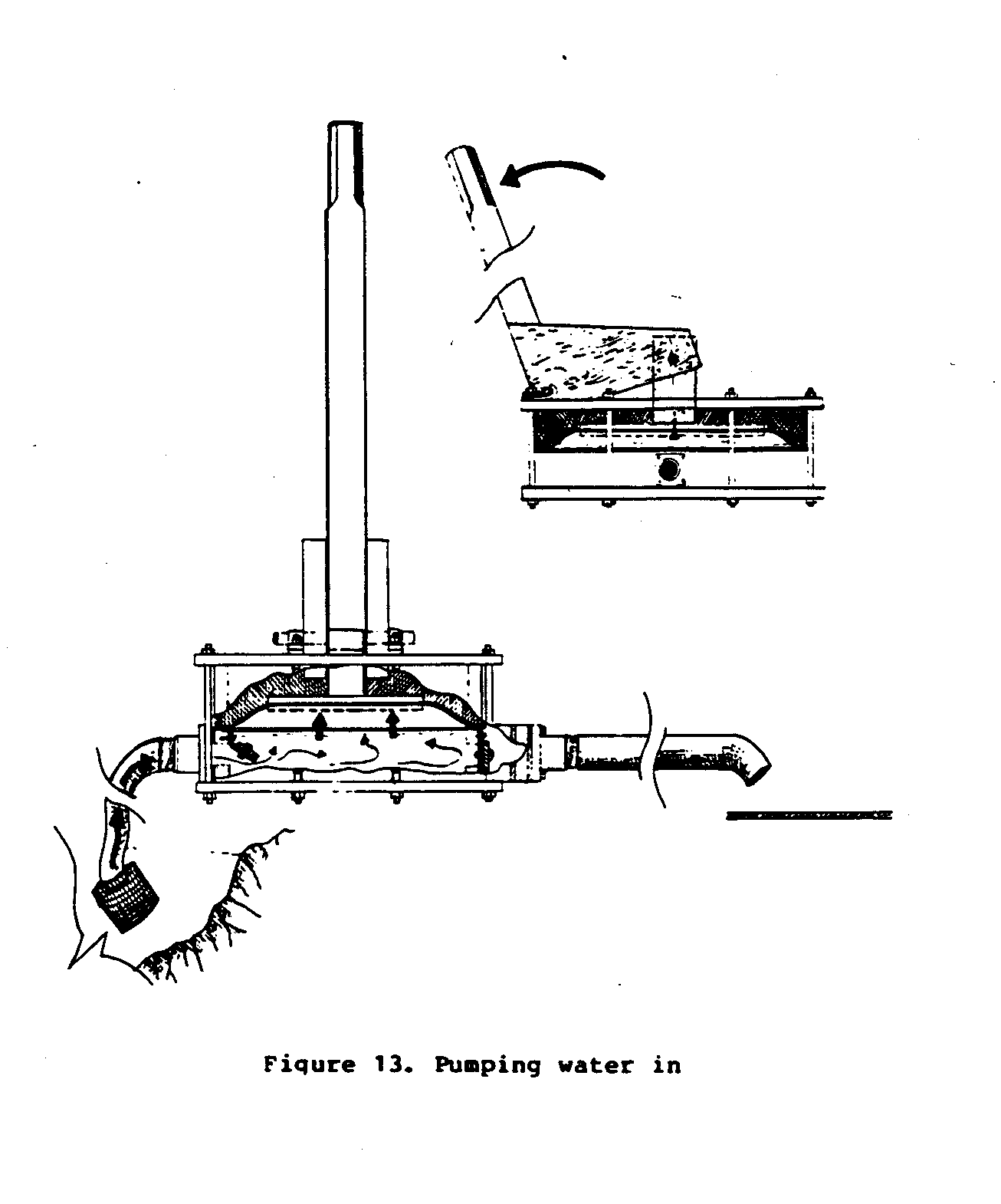
When you are ready to use the pump, fill the diaphragm chamber with water. Do this by pivoting the pump on its inlet side. Prop the outlet valve open and pour water through the valve. With the pump in this position and the inlet hose inserted into the water source, operate the pump while pouring water into the chamber. The pump will soon start working. The time and effort needed for this depends on the length of the inlet hose. Usually five to ten strokes of the handle will be sufficient. <see figures 13 & 14>
Two pumps can be mounted side by side, as shown in Figure 15,
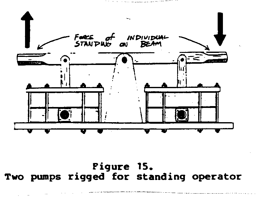
and operated by a person standing on the beam and rocking from side to side. This is an easy way to operate the pump.
The rubber valves and the diaphragm may need replacing after 9 to 12 months when the pump is used two to three hours a day. You may need to replace them sooner if the water is dirty, or if the pump is used more every day, or if the rubber material is not in good condition.
If the pump does not pump water, the trouble probably is with air leaks either from faulty construction or alignment of the valves, or worn valves or diaphragm.
A small quantity of grease should be applied to the two pivot rod mounting clamps, Part 1d, when they squeak.
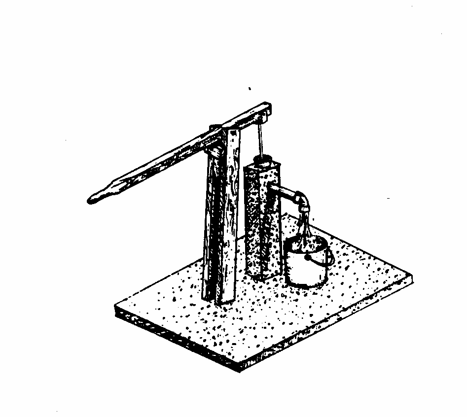
PITCHER PUMP
Variations of the pitcher pump, a piston-type handpump, have been in use for centuries in many parts of the world. Commercially manufactured pumps are produced in a wide range of sizes to meet many different needs. The pump presented here <see image> is
durable and easy to use. It is a good design for production in a central shop. Or it can be made by anyone with access to the necessary equipment.
The pump lifts between eight and ten gallons per minute for about 10- to 15-foot suction. The maximum lift is about 20 feet.
Some welding may be required, as well as pipe threading, but alternative construction processes are given to accommodate available resources and skills.
MATERIALS AND TOOLS
MATERIALS:
Part Number Description Quantity
1 2" x 5" x 24" hardwood handle 1 1a 1/4" x 3" steel rod or G.I. pipe; 1 pin in each end 1b 3/8" x 3-1/2" steel rod or G.I. pipe; 1 pin in each end 1c Metal strap 1/4" x 1" x 8" 2 2 3" I.D. x 18" - G.I. pipe cylinder 1 (threaded on one end) 3 1/2" dia. x 18" steel rod 1 (threaded on one end at least 1") 3a 3/16" dia. x 1-1/2" cotter pin or nail 1 3b 1/2" I.D. flat washer 1
Part Number Description Quantity
3c 2-1/2" O.D., 1/2" I.D. rubber 1 inner tube disk 3d 2-3/4" dia. x 1-1/2" hardwood 1 block (piston) 3e 1/8" x 1" x 9-1/2" leather strap 1 Note: brads or screws required to hold leather strap to 3d. Will need about 10 to 12 1"-long flat headed nails; use brass nails if available 3f 1/2" machine nut--to fit on 1 Part 3 4 3-1/2" to 4" I.D. pipe coupling 1 4a 1/4" x 1" x 1-1/2" steel bar stock 4 4b 1" I.D. pipe flange. Substitute 1 can be a 1" I.D. pipe coupling welded to a 1/4" thick x 3-1/4" dia. steel ring. 5 1/8" x 2-1/2" dia. leather disk 1 cut to an oval shape, shorter dia. [+ or -]2" 5a 1/4" I.D. x 1-1/2" O.D. sheet 1 metal disk 5b 1/4" x 1" machine screw and nut 1 5c 3/16" x 1-1/2" machine screws 2 and nuts 6 1" G.I. pipe length as needed to 1 reach aquifer
G.I. - Galvanized iron I.D. - Inner diameter O.D. - Outer diameter
TOOLS:
Hammer Drills for metal, sizes 3/16", 1/4", 3/8", and 1/2" Wrenches (pliers and pipe wrench) Wood plane Hacksaw Screwdriver File welding equipment Wood saw Shears capable of cutting sheet metal, leather, and rubber Emery paper
CONSTRUCTION
- Handle Assembly, Figures 2, 3:
Cut the handle according to the following drawing (Figure 4)
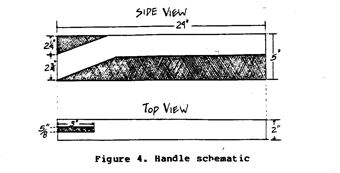
from good hardwood stock measuring 2" x 5" x 24".
Cut a 3" x 5/8" slot, centered on the 2" edge, into the short end of the handle. This slot will hold the piston rod. Taper and smooth the long end of the handle to permit easy hand action.
Drill a 1/4" hole through the slotted end, about 1/2" in from the top and front edges. This hole will accommodate pivot Part 1a which secures the piston rod.
Drill a 3/8" hole at a point 5" or 6" from the 1/4" hole, and parallel to it, approximately equidistant from top and bottom edges. Position this hole carefully in order to prevent as much as possible the horizontal movement of the pump rod.
Bend Parts 1c, the 1/4" x 1" x 8" steel straps, into a 20[degrees] angle at the midpoint.
Drill 3/8" holes at one end of the straps. This is to support the handle via the pivot Part lb.
Weld the straps to the cylinder as shown in the cutaway view (see Figure 5).
Alternate method of constructing the handle, Part 1c:
Part 1c could also be constructed by slotting and drilling a 12" long section of 2" x 4" piece of wood to accommodate the handle. The wooden piece could then be strapped onto the cylinder by two wooden clamps, each of which would be cut to fit halfway around the cylinder, thus avoiding the necessity of welding equipment.
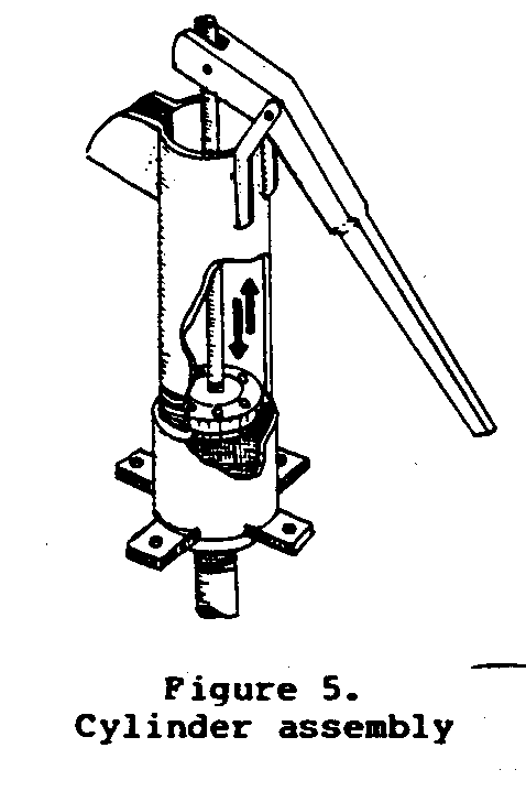
- Cylinder assembly, Figure 5:
The cylinder is made simply from a piece of 3" inside diameter G.I. pipe. Make the spout for the cylinder by cutting two slots in the unthreaded end of the pipe. One slot should be cut 3" long straight down from the unthreaded end; the other slot should be cut 2" across the unthreaded end and at a point perpendicular to the bottom of the first slot. Bend the two resulting tabs outward and weld a metal plate across the bottom.
To eliminate welding, the bottom of the spout could be bolted to the sides.
The inside of the cylinder must be sanded as smooth as possible with emery paper or equivalent to prevent unnecessary wear on the piston leathers.
- Piston rod assembly, Figure 6:
The piston rod assembly is as shown (3, 3a), but a few additional points are worth mentioning: a 1/4" hole should be drilled through the piston rod 1/2" down from the top. Another hole 3/16" diameter should also be bored 2" up from the threaded or bottom end of the rod.
- Piston assembly, Figures 7, 8, 9:
Carefully drill the holes in hardwood block 3d. The 1/2" diameter center hole must be exactly on center and parallel to the sides of the block. The 3/8" diameter side holes should be equidistant from the center hole, and should also be parallel to the sides of the block. The distance from the center hole to the centers of the side holes should be 1" (See Figures 7 and 8).
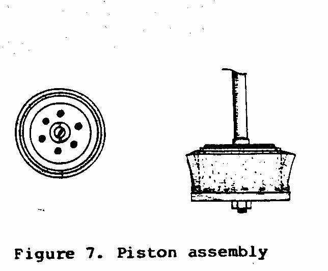
As shown in Figure 9, the lower
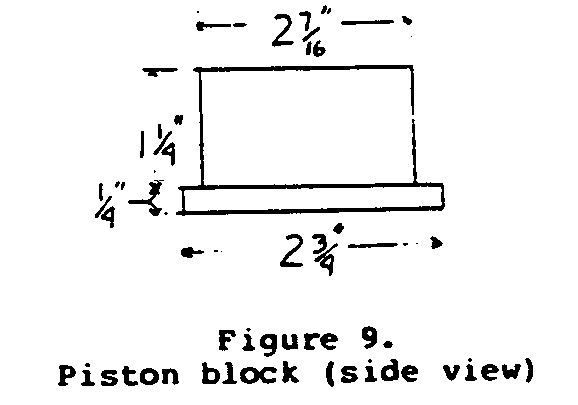
portion of the piston block has a slightly larger diameter than the upper portion. The lower portion should be 1/4" thick and 2-3/4" in diameter. The upper portion should be 2-7/16" diameter (See Figure 9).
Part 3e is a section of leather strap wrapped around the piston block and tacked onto the smaller upper section. Tack the leather along its lower edge to permit the upper half to bend outward. The leather strap should be pounded with a hammer all along its upper edge before it is tacked to the block. This will force the leather into a cone shape so it will seal more effectively against the cylinder wall. It might be helpful, but is not necessary, to sew the strap together at the joint.
Finally, fit rubber disk 3c over the top of the piston. Pit large metal washer 3b over 3c.
- Connector/reducer assembly:
The connector/reducer assembly consists of a 3-1/2" or 4" (inside diameter) pipe coupling (4) that has a pipe flange (4b) welded onto one end. The mounting holes in the pipe flange are welded shut. If a pipe flange is unavailable, a substitute can be made with a 1" (inside diameter) pipe coupling and a steel ring (3-1/4" outside diameter, 1-1/4" inside diameter and 1/4" thick). The 1" coupling is then simply welded to the ring and the resulting assembly welded to the connector as before. Take care to make these welds watertight.
The connector also serves as a housing from which the pump can be mounted.
Weld four 1/4" x 1" x 1-1/2" metal bars (4a) at right angles to each other on the very bottom end of the pipe connector. Bore 3/8" diameter holes in these four metal bars. Note that the metal bars should be slightly rounded where they contact the pipe coupling (See Figure 12).
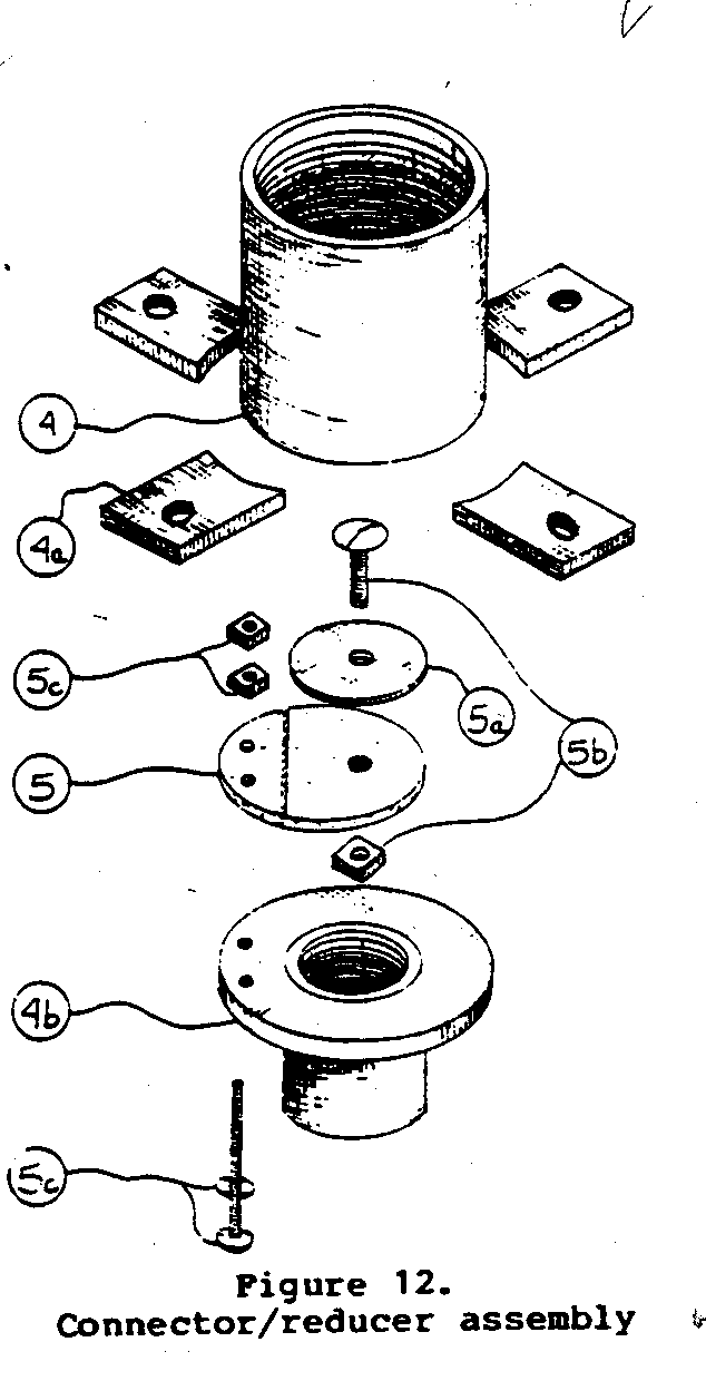
- Foot valve assembly, Figures 10, 11:
The foot valve assembly consists of an oval-shaped leather disk (5), a sheet metal disk (5a), a 1/4" x 1" machine screw and nut (5b), and two 3/16" machine screws with nuts (5c).
Shape the foot valve leather into an oval as shown in Figure 12 (larger diameter 2-1/2"; smaller diameter 2"). Punch a 1/4" hole through the leather at a point about 5/8" to 3/4" in from one end. Bolt the sheet metal disk to the leather oval through this hole as shown in the diagram. The bolt and sheet metal disk reinforce the leather as it closes over the suction inlet. Cut two 3/16" holes through the leather about 1" apart and 1/2" in from the closest point of contact with the side of the leather.
Drill two corresponding 3/16" holes into the reducer assembly (4b) as shown in Figure 12. Mark these holes carefully as they determine the location and effectiveness of the foot valve leather to a considerable extent.
Cut a slight groove, 1/32" deep across the leather (5) so that it will bend along a specified line. Cut the groove as close as possible to the 3/16" nuts that mount the leather disk.
Insert the 3/16" machine screws through the bottom of the reducer assembly. Then place the foot valve leather, then the two 3/16" nuts. Apply some tar or pitch to the holes in the reducer before and after the insertion of the 3/16" machine screws to prevent air and/or water leaks.
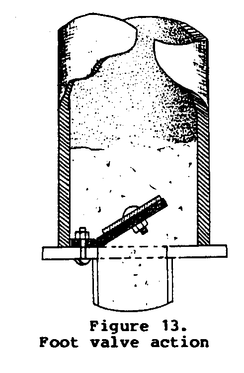
The effectiveness of the foot valve will be determined by the seal it makes with the suction inlet. Be very careful to make the suction inlet as flat and smooth as possible before mounting the foot valve leather. It is very important to locate the foot valve so that it does not come in contact with the piston as this will make operation very difficult. <see figure 13>
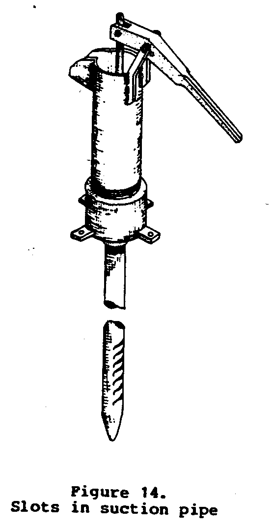
- Suction pipe and inlet filter assembly:
Cut 1" diameter pipe to the required length. Note that the total lift of water must not be more than 20 feet.
Make the inlet filter by cutting approximately 75 slots 1" long at the bottom end of the suction tube. The width of the slots will equal the width of the hacksaw blade. Start cutting slots 2 ft. from the bottom of the pipe. Space slots over a 2 ft. length. This will give a 2 ft. sand trap. Take care to stagger the slots and avoid cutting too deeply as this will weaken the suction pipe.
Pound the bottom end of the pipe flat to force the water to be drawn in through the slots. Or thread the pipe and install an end cap. <see figure 14>
OPERATION AND MAINTENANCE
The pump must be primed to begin working. Pour water into the cylinder while pumping the handle for a few strokes. This develops a low pressure area below the piston and above the foot valve. The low pressure area draws water in through the foot valve as the piston moves upward. At the top of the stroke of the piston, the foot valve will close and prevent the water from escaping back down into the suction pipe.
As the piston moves downward, the water is forced through the holes in the piston, past the rubber disk and into the area above the piston. By the time the piston is at the bottom of the stroke, most of the water should be above the piston. As the piston is again lifted, the water spills out of the spout. At the same time, more water enters through the foot valve.
Quite often when this type of pump is first installed in a bored tube well, it becomes necessary to draw very fine silty and clay particles through the filter before the water will enter the suction tube readily. This process is known as "developing the well" and it may take from two hours to several days of continual use of the pump before the water becomes clear. If the pump is mechanically sound, you will note that the pump also becomes easier to operate as the water becomes clearer.
The piston and foot valve leathers will need to be replaced periodically. Exact life of the piston leather and foot valve depend on the quality of leather. Pumps made with factory machine tools and materials will often last 7 or 8 months under continued use before the leathers must be replaced.
If, after the well is developed, i.e., the water is clear and flowing freely, the pump continues to be easy to operate but draws little water, an air leak may have developed. Air leaks may occur in one of four places: 1) where the cylinder is screwed into the connector reducer unit; 2) where the suction tube is screwed into the connector reducer unit; 3) where the piston rod meets the rubber disk and/or, 4) where the piston leather meets the cylinder.
If the leaks occur in the threaded parts, put pipe compound or equivalent on the threads before screwing the parts together.
If the leaks occur where the rubber disk contacts the piston rod, replace the rubber disk, making the inner hole slightly smaller than 1/2" in diameter.
If the leaks occur where the piston leather meets the cylinder, replace the piston leather and/or rub it with a good leather oil or equivalent.
Grease moving parts at frequent intervals.
SPANGLER PUMPS
Commercial pumps have traditionally been made of cast iron because of its strength and durability. And the cylinders have often been lined with brass to ensure smoothness and prevent wear on the pump leathers. Unfortunately, however, use of these metals has often made the pumps either too costly to purchase or too complicated to fabricate. <see image>
During the early 1970s, VITA Volunteer C.D. Spangler, a sanitary engineer, began experimenting with pumps made of polyvinyl chloride pipe. PVC pipe is lightweight, durable, easy to work with, and relatively inexpensive. It can be made into pumps that are far easier to build, install, maintain, and repair than cast iron pumps. It is now available in most countries in sizes suitable for construction of even deep well pumps. And pumps made of PVC pipe can be sealed and used in sealed wells so that they are well suited to potable water supplies. VITA published Spangler's original designs in 1975 in Handpumps for Village Wells. They have found wide acceptance, especially in southern Asia. Chulalongkorn University in Bangkok tested the pumps extensively and suggested improvements to the piston assembly in an environmental health project supported by the World Health Organization and the United Nations Development Programme. By the end of 1981, nearly 10,000 of the pumps were in use in Thailand alone.
PVC pumps are especially suitable for community water supplies and as the basis for small scale manufacture. The parts are relatively simple and can be fabricated by small shops or factories in a given design. Most countries now have plants to extrude PVC pipe, even where the raw material is imported.
This section of Six Simple Pumps differs somewhat from the other chapters in that it actually covers two separate pumps, one for shallow wells and one for deep wells. Both are made of PVC pipe, however, and so have very similar construction techniques. Pipe sizes and piston styles vary with the type and depth of the well being used. Basic methods for working with PVC pipe are included, as are techniques for making a variety of valves and pistons. Construction drawings for each of the pumps provide guidelines to the sizes and quantities of materials required.
Both of the pumps are of the piston type. The shallow well pump, for a water table 5-20 feet beneath the surface of the ground, will discharge 5-15 gallons per minute. For the deep well pump, pump discharge depends on the diameter of the piston, the length of the stroke, and the number of strokes per minute. If the water level is less than 30 feet below the surface of the ground, the cylinder could be up to 4 inches in diameter. If the water level is farther from the surface, the longer column of water that must be lifted becomes heavier and a greater effort is required to operate the pump. The greater the distance to the water level, the smaller the diameter of the piston should be, so it is not too hard to pump.
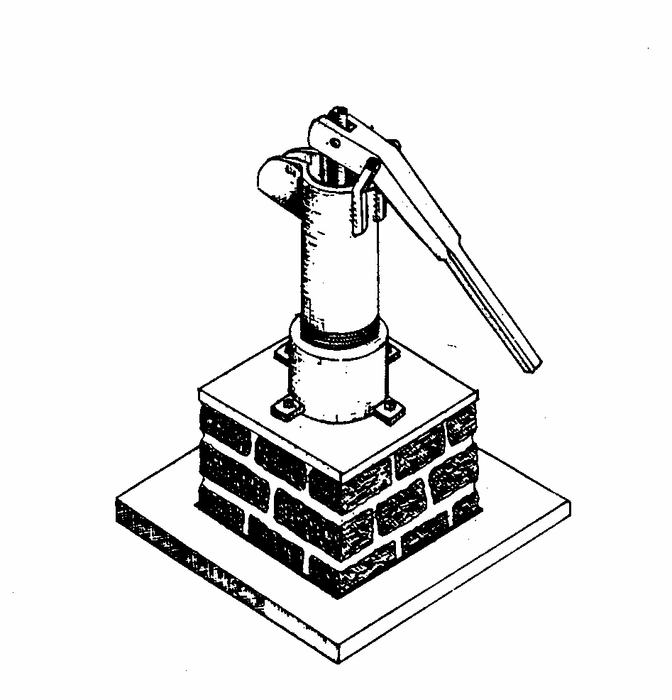
The traditional pump stand is made of cast iron. It supports the handle and contains the discharge spout. Direct suction pumps, or shallow well pumps, have the piston and lower valve in the pump stand, which is also the cylinder. Traditional deep well pumps have the cylinder with piston and valves below the lowest water level in the well and suspended from the base of the pump stand by the discharge pipe.
In the designs presented here, the handle is supported on a separate post next to the well and pump stand. The pump stand without the handle provides only a passage for the rod, a channel for the water, and a discharge spout. In shallow wells it is also the cylinder and the support for the suction pipe. Since the pump stand does not bear the load and stress caused by the handle, it need not be so strong, and therefore does not have to be of cast iron.
If the PVC pump stand needs protection, a concrete pipe, brick pier, or wooden post can be placed around it, with the spout extending beyond the protection. Such a pump will use a minimum of expensive materials and can be easily repaired.
The post supporting the handle can be made of concrete, bricks, stone, or wood, depending on local availability and cost. The distance from the post to the pump can vary so as to provide the best leverage. The closer the handle pivot is to the well, the easier it will be to pump. The length of the stroke will be smaller, however, and so will the discharge.
The handle can be made of wood that can be replaced locally when worn or broken. The handle should also have a stop on the support post so it will not strike the top of the pump stand.
The seal between the piston and the cylinder wall is usually provided by a leather or rubber disk with a turned-up edge, called a "bucket." Quality control is important if good leather or rubber buckets are to be obtained. These are not expensive and if good ones cannot be obtained locally, they can be imported from many countries in the developing world--India, Pakistan, Korea, Thailand, and others.
The pump is simple, dependable and low in cost. The object of a pump project should be to develop a pump that can be produced in quantity by local technology to meet the needs of most of the rural population in the area. A pump similar to that shown in Figure 2 has been developed in Thailand at a cost of about
US$30. It delivers about 5-15 US gallons per minute depending on depth to water. It is being used for irrigation as well as for domestic purposes.
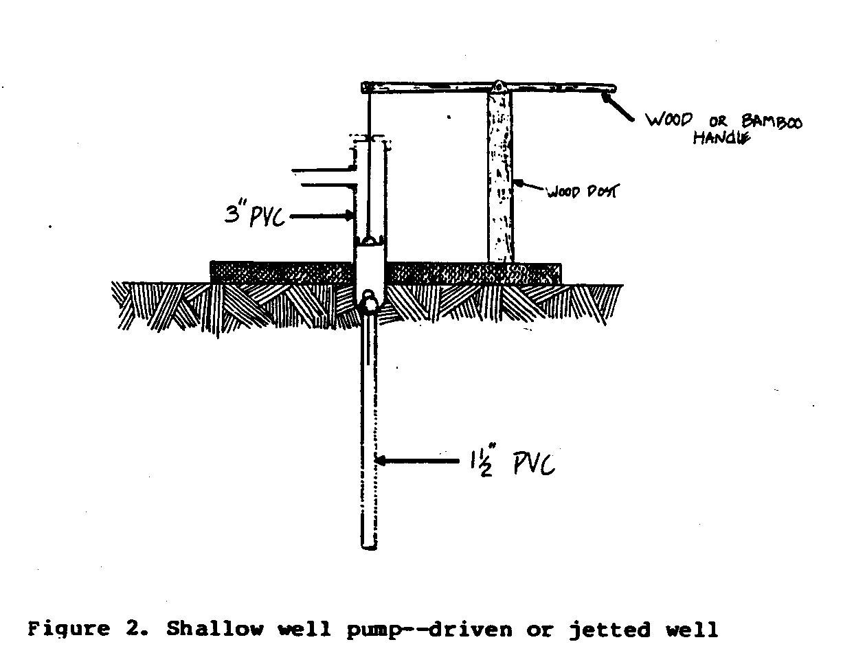
SHALLOW WELL PUMP
This suction type pump is usually used with shallow wells but may also be used with deep driven, jetted, or drilled wells where the pressure in the aquifer is enough to keep the water level at all times within 20 feet of the ground surface. The pump stand is a length of 3" PVC pipe, which also serves as the pump cylinder. The well casing itself may be the suction pipe in driven or small-diameter jetted or drilled wells. In dug wells, the 1-1/2" suction pipe is suspended from the 3" PVC pump stand, which in either case must be set firmly in the platform.
The top of the pump stand should be several inches above the spout and have a removable cap with a slot to allow for the small back and forth movement of the rod. To remove the piston and replace the leather bucket it is only necessary to disconnect the rod from the handle, remove the cap and pull out the piston. If the lower valve is a poppet type valve it can have a small loop at the top and can be fished out using a wire with a hook at the end.
DEEP WELL PUMP IN CASED WELL <see figure 3>
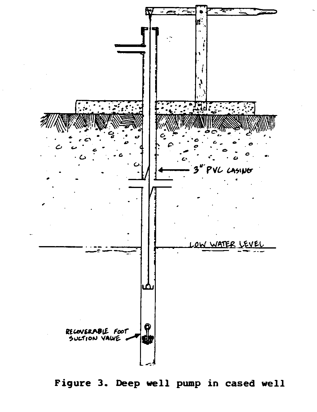
PVC casing can be used in either jetted or drilled wells. In jetted wells the hole is full of water and the PVC casing can be placed in the hole with little possibility that there will be caving before the casing is in place. The same is true of wells drilled by the rotary process. With percussion drilled wells the best procedure is to drive a metal casing and then insert a PVC casing and screen after the aquifer has been penetrated. The metal casing is then removed to be used again. In wells with PVC casings, the PVC casing can also act as the cylinder.
If the water level is less than 50 feet below the surface, the handle support should be placed to enable the pumper to lift the column of water in a 3" PVC casing without too much exertion. If the water level is deeper than 50 feet, a 2-1/2" of 2" PVC casing should be used.
The lower valve can be the same basic design as the piston valve, except that it has a slightly larger diameter. It then fits very tightly in place and does not need a separate valve seat. But it can be removed for repairs if necessary. Another method is to fix a permanent valve seat into the casing at a joint below the farthest travel of the piston. The valve seat can be made of brass, glass, or flat PVC cemented into place. In this case a flap or poppet type of valve should have an eye bolt with the loop at the top so the valve can be fished out with a hook for repairs as necessary.
The length of the rod is chosen to place the piston below the lowest water level in the well. The piston may be standard, with one or two leathers. The top of the well and the handle support are the same as in the suction type shallow well pump. It is easy to remove the rod and piston for repairs.
MATERIALS AND TOOLS
MATERIALS:
PVC piping as indicated Cement Pipe compound
A. Pump Body and Well Pipe Deep Well
- Well casing PVC pipe rated at 120 lb/in.sup.2
- Threaded couplings or cement unions to join the well casing pipe sections
- PVC inlet screen, commercial or locally fabricated. Length depends on depth and flow rate of the aquifer (consult with driller)
- PVC end cap (inlet screen body)
- 1.5" to 2" PVC outlet spout
Shallow Well
Same as above except that Numbers 3 and 4 are generally not required, if for dug well.
B. Flap-Type Piston Assembly
- Valve body--hardwood
- Threaded steel assembly rod (galvanized would be good, but is not essential)
- Brass nut
- Brass washers
- Rubber disk (valve flap)
- Piston leather (strip approx. 1" x 7", cut to fit)
- Galvanized fitting to connect to pump rod (specification depends on type of pump rod used)
C. Recoverable Flap-Type Foot Valve
Same as B above except a threaded brass rod is substituted for Number 1.
Also, a galvanized eye bolt may be used instead of threaded brass rod in some situations.
D. Pump Rod Galvanized
- Galvanized steel rod, sections 3/8" to 1/2" with threaded ends. (Number and length depend on depth of well)
- Galvanized steel threaded unions, as required
- Galvanized lock nuts, as required
- Top and bottom connections to piston and pump handle (specifications will depend on design chosen)
PVC
- 1" PVC pipe. 120 lb/[in.sup.2] rating in sufficient length
- Bamboo or hardwood support and guide blocks (enough to place four every 6 to 7 feet)
- Brass nuts and bolts to attach guide blocks
- Top and bottom threaded couplings to connect to piston and link to pump handle
- Steel link-rod coupling
- Self tapping screws to attach pilot block
TOOLS:
Hacksaw File Hammer Emery paper, sandpaper Screwdriver Pliers Wrenches Shears capable of cutting leather and rubber Clamps
CONSTRUCTION
WORKING WITH PVC PIPE
Cutting
Make cuts square with long axis of the pipe, using a mitre box or temporary jig at the work site. Use a wood-working saw or a hacksaw with a coarse-tooth blade. Remove all burrs on cut edges with a scraper and sandpaper.
Threaded Joints
Use threaded joints wherever pipe sections must be taken apart for repair and maintenance. Thick wall (schedule 80) pipe sections may be threaded externally (male thread) with a pipe thread cutter and joined with a threaded female union. Care should be taken when joining two sections of casing with a union to be sure that the two ends are butted flat together with no space between them.
When joining thin wall and small diameter pipe, use a combination cement and threaded coupling. If the casing is made of bell and spigot pipe, the bell end should always be down. Drive the straight end as far as possible into the bell. This will make it easier to remove the piston and/or lower valve.
Where threaded joints must be water tight, use a non-hardening, non-solvent, non-toxic joint compound.
Note: If small diameter PVC pipe is used <see figure 4> as the pump rod in
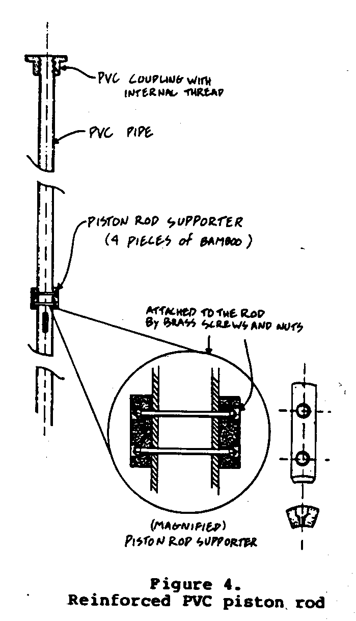
conjunction with the Recoverable Flap-Type Foot Valve, use lock nuts at each joint to prevent the sections from unscrewing during installation or recovery of the foot valve.
Cemented Joints
Cemented joints are generally cheaper than threaded joints and are used where the joint is expected to be permanent. Use female unions to join sections of pipe. End caps, "T" fittings, reducing unions, and other fittings can also be cemented directly to plain pipe.
The surfaces to be joined must be free of oil, water, and dirt. Clean the surfaces with fine sandpaper or solvent cleaner.
Test each fitting and joint prior to cementing.
Apply a light, even coating of the solvent cement recommended by the pipe manufacturer. The cement dries quickly, so join the parts immediately. Give each joint a one-quarter turn as it is being assembled (not after) in order to distribute the cement evenly. Allow the joint to cure for 5 minutes before installation or application of mechanical stress.
PUMP ROD AND PISTON
Metal Rod
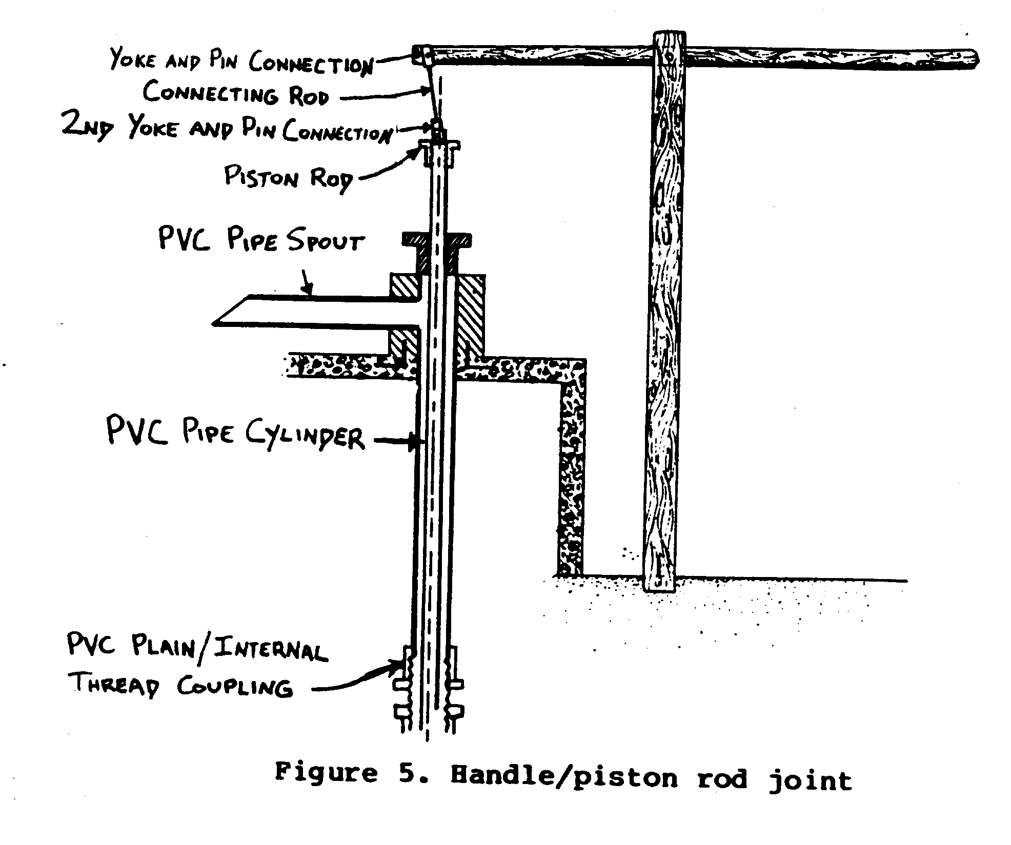
Metal rods are generally available commercially. Or, they can be made from 1/4" to 3/8" galvanized steel rod and galvanized steel pipe fittings. The rod makes a movable connection at the top of the piston and with the pump handle using a yoke and pin arrangement at both places.
The yoke and pin connection between the rod and the handle will move through a small arc and will cause a small side movement in the upper end of the pump rod. This creates a slight rocking motion in the piston as it moves up and down, and causes uneven wear on the piston leathers or rubber buckets. To overcome this, the Thai researchers added another yoke and pin connection to the piston rod. The second connection greatly extends the life of the leathers, but the pins in both connections must be parallel to each other or the second connection will not be effective (See Figures 5 and 8)
PVC Pipe
The pump rod can also be made of 1" PVC pipe. This has the advantage of being cheaper, lighter, and non-corroding. Use thick wall, pressure-rated PVC. Since PVC pipe is flexible, attach wooden guides to the pipe to prevent the pipe from buckling on the down stroke (See Figure 6). The guides will
help prevent the side to side movement at the rod caused by the pumping action. Connect the top of the PVC pump rod to the pump handle with a double-jointed link, as described above (See Figure 5).

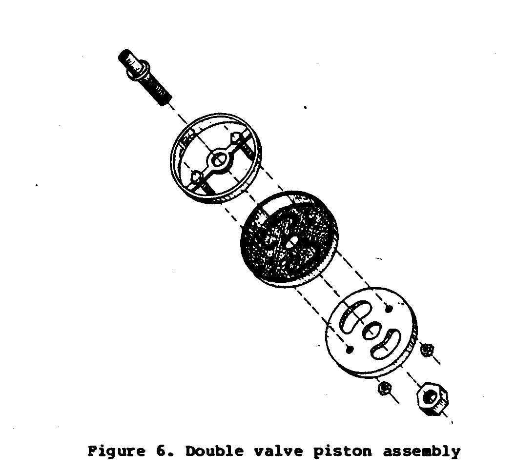
Piston
Ready-made piston valves are usually readily available and inexpensive. However, if desired, a piston valve can be hand fabricated according to the instructions on pp. 22-24 of Chapter 2, Pitcher Pump.
The Thai researchers found that a double piston valve (Figure 8)
made the pump more efficient and prevented undue wear on the leathers. Other types of valves are shown in Figures 6 and 7.
FOOT VALVE ASSEMBLY
There are several good designs and means of fabricating foot valves for the piston pump. One of the best options is to purchase a high quality ready-made valve and incorporate it into the assembly of the pump. If possible, choose a foot valve that allows easy replacement of the wearing parts of the valve. One type of recoverable flap-type foot valve that can be locally manufactured is shown in Figure 10.
Other options for the foot valve are a ball valve in a seat (though this may cause excessive wear), a leather or rubber flap valve, or a poppet valve (see Figure 9). If the lower valve seat is a permanent ring of PVC or other material, it can be cemented inside the casing at a joint as the casing is assembled.
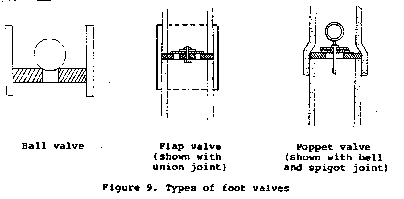
Another method has been used by Rev. George Cotter of the Buhangija Mission in Shinyanga, Tanzania. This is to crimp or squeeze in place the PVC ring that acts as a seat for the steel ball making the foot valve. Once the length of PVC pipe has been determined, immerse the lower end in hot oil until soft, insert the ring an inch or two up the pipe, and use common auto radiator hose clamps to squeeze the pipe above and below the ring position. The hose clamps can be used again and again as the PVC pipe will not return to its original shape once it has cooled. The easiest way to handle the hot oil is simply to have a paint can (or other metal container) of used engine oil. This can be reheated again and again. Cotter also suggests that the end of a section of PVC pipe can be softened and flared to fit over a metal pipe or another section of PVC pipe by this same method.
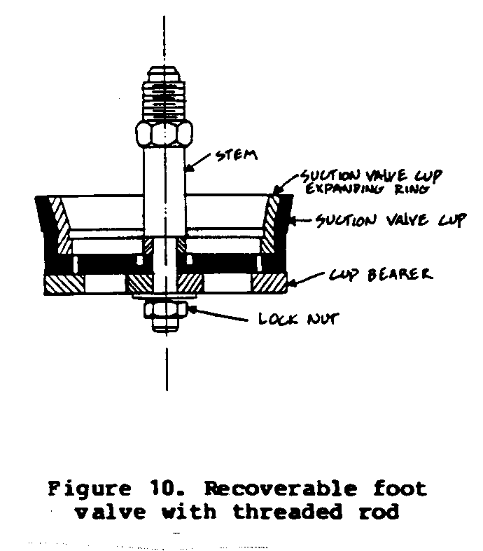
RECOVERABLE FLAP-TYPE FOOT VALVE
Construction of this valve is essentially the same as the construction of the piston assembly, with minor changes.
- The valve body and leather seal must fit very tightly in the well casing. Size will vary according to the type of PVC pipe used and so cannot be specified in advance. The valve is wedged tightly into place in the well casing to prevent it from shifting during use. It can, however, be removed for maintenance.
- While the piston assembly is held together with a galvanized steel bolt, the foot valve is assembled with a brass bolt with exposed threads. The brass threads will not corrode significantly and will allow a threaded connection to be made whenever it is necessary to repair or replace the foot valve (See Figure 10).
- Alternatively, fasten the foot valve with an eye bolt as shown in Figure
- The valve can then be removed by means of a long hook.
PVC INLET SCREEN CONSTRUCTION (DEEP WELL)
The inlet screen sits below the pump in the well. It prevents sand from entering the pump. PVC is a superior material for construction of the screen because it does not corrode and does not tend to become encrusted with mineral deposits.
Inlet screen can be purchased or fabricated, and the International Rural Water Resources Laboratory at the University of Maryland has developed a fabrication method that is readily adaptable to local, small-scale manufacturing facilities (See Resources section). Making the screen by hand is tedious, but may be the only option. If the screen is made by hand, the following specifications must be used:
2" heavy wall PVC, 3 to 9 feet long (depending on depth and flow rate of water).
Cut fine slots one inch apart as shown in Figure 12. Do not cut more than one-third of the way through the pipe.
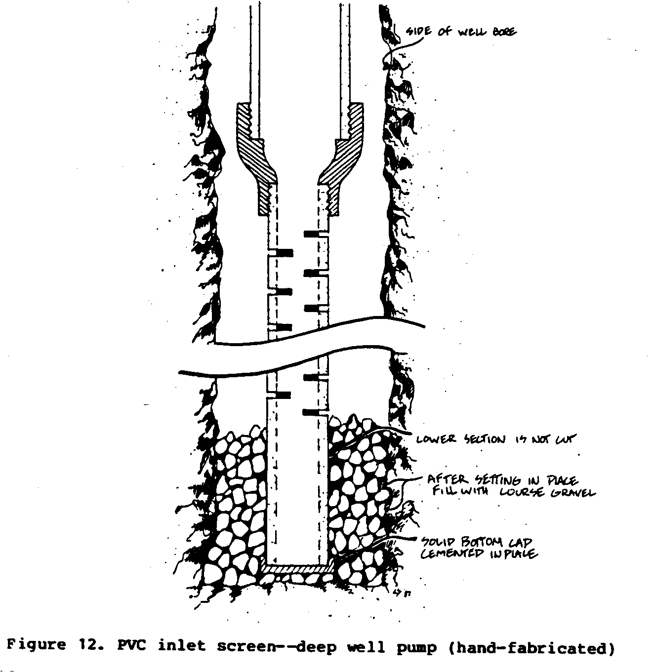
Start cuts 24" from the bottom end of the pipe. This provides for a 24" sand trap.
Slots should alternate and not be directly opposite one another. Cut at least 75 slots. After the screen and well casing are in place, backfill around them with fine gravel or coarse sand that has a particle size slightly larger than the slots.
PUMP STAND AND OUTLET SPOUT
In both designs presented here, the pump stand is an extension of the pump cylinder and well pipe. A PVC spout must be attached to this PVC well pipe. A piece of 1.5" to 2" PVC pipe is cut to the desired length. One end is then "welded" to the 3" well pipe: the end of the spout that connects with the well pipe-is-cut and sanded until it fits the exact curvature of the well pipe. A spare section of well pipe or iron pipe with the same outside diameter can be used as a sanding form for this purpose.
Cut a hole the same size as the internal diameter of the spout in the well pipe. Fix the spout into place as described under "Cemented Joints". Support the spout until the cement sets (about 5 minutes).
To assure longer life, it may be desirable to make a protective enclosure for the pump stand. A wooden, brick, or stone "box," or poured concrete are all options that have been tried successfully. Choice will depend on cost and availability of materials.
PUMP HANDLE DESIGN <see figure 13>
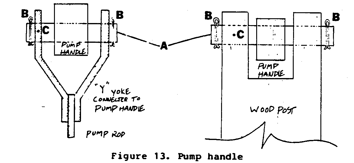
A. Smooth metal rod or section of G.I. pipe that works as bearing. 5/8" in diameter.
B. Cotter pins to hold bearing in place.
C. Pin through bearing and support so bearing will not rotate. The angular rotation will take place in the wooden handle, which is easy to replace when it wears.
D. The distance along the handle between the bearing holes should be set so the mid-point of the arc through which the end of the handle travels is over the center of the well casing. This is important to minimize the slight rocking motion of the piston (See Figure 14).
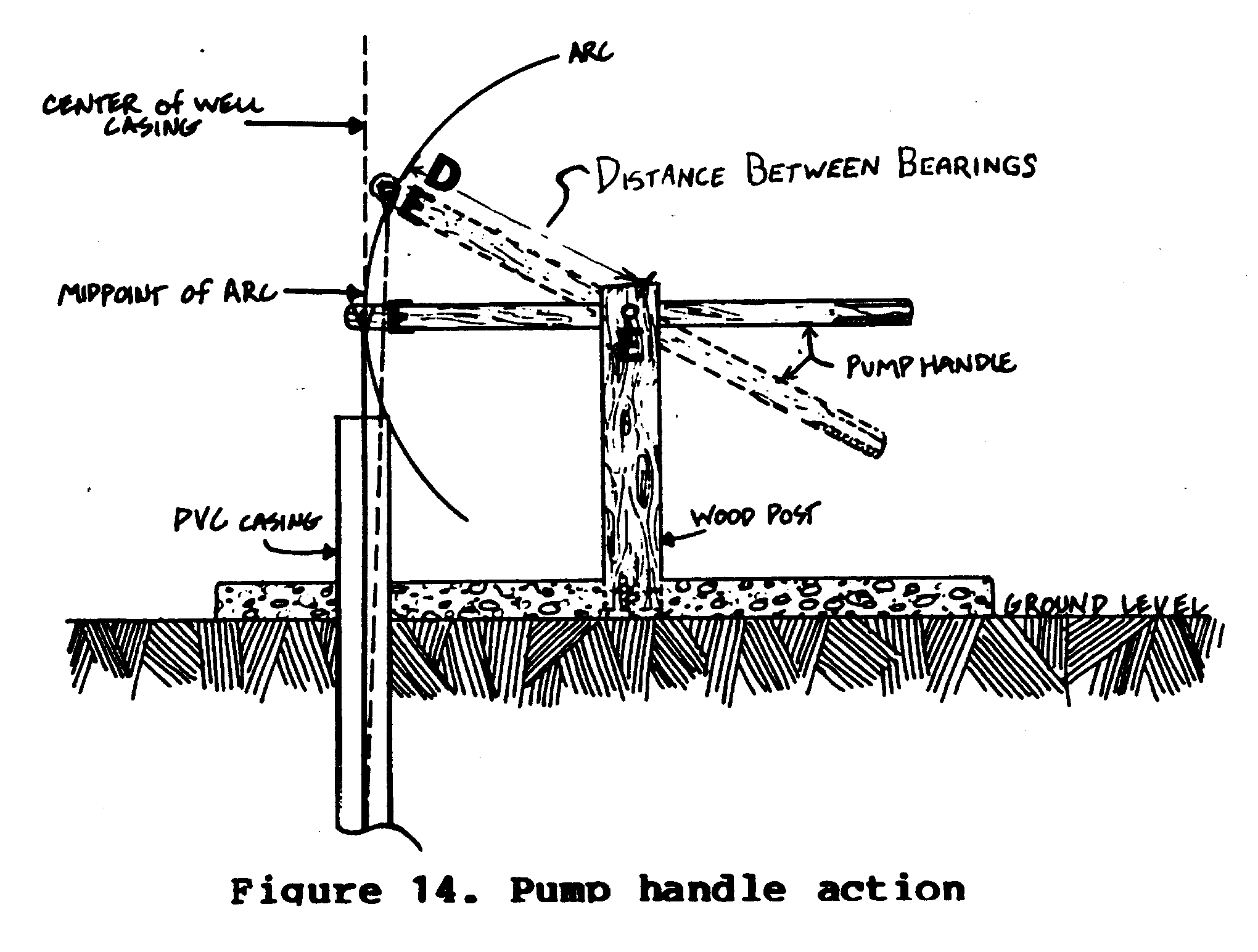
E. The bearing holes in the handle should give a smooth, tight fit on the bearings. The holes should be soaked with used motor oil before installation, and after installation should be lubricated often with a few drops of oil.
ASSEMBLY AND INSTALLATION OF DEEP WELL PUMP
In some situations it may be necessary to assemble and install the pump and well pipe as quickly as possible in order to reduce the risk of collapse of the well bore. In these situations, it is advisable to use threaded well pipe joints as these may be put into use without the delay involved in waiting for cemented joints to cure.
In all situations it is advisable to pre-assemble or "test fit" all PVC components and pump parts to assure that everything will go smoothly during the actual installation. It is also advisable to pre-test the pump, especially if the piston and foot valve have been hand fabricated. If a recoverable flap-type foot valve with a hardwood valve body is used, install the valve in the pump cylinder and soak the assembly in a bucket of water for several days in order to test for fit and removability.
To assemble and install the pump and well pipe:
- Assemble the inlet screen.
- Position the foot valve seat, if required, between the inlet screen and the part of the well pipe used as the Pump cylinder.
- Cement the inlet screen coupling to the pump cylinder section.
- Tie a safety line to the top of the pump cylinder section and lower the combined inlet screen and pump cylinder section into the well bore until only a short section remains above ground.
- Tie a safety line to the top of the next section of well pipe and join it to the top of the pump cylinder. If a cemented joint is used, wait 5 minutes before proceeding.
- Untie the safety line from the pump cylinder and carefully lower the combined sections into the well bore.
- Add additional well pipe sections as in steps 4-6 until the inlet screen is resting on the bottom of the well bore and a section of well pipe 3 feet high remains above the top surface of the well platform.
- Backfill the bore with enough fine, clean gravel or coarse sand to cover the inlet screen section and the pump section. The remainder of the well bore should be backfilled with dry clay, if cheap and available. The clay will form a grout-seal to prevent surface water from running down the side of the well pipe and contaminating the well. If clay is too expensive, fine soil should be used and a cement-grout used to fill the last 10 feet of the well bore.
- Pour the concrete for the well platform (if not already done) and set the pump handle stand in place with concrete, metal, or wooden clamps. Be sure to permit concrete to cure properly.
- Pour the concrete for the pump stand cover if this option is selected, or install a protective wooden box around the pump stand.
- Install the spout.
- Lower the recoverable foot valve if this option is selected. Using the threaded-brass bolt and nut method of foot valve recovery is recommended for wells over 30 feet deep. For shallower wells, a hook ring can be used instead of a threaded connection and the foot valve pushed into place with a couple of sections of 2" PVC pipe.
- Lower the piston assembly.
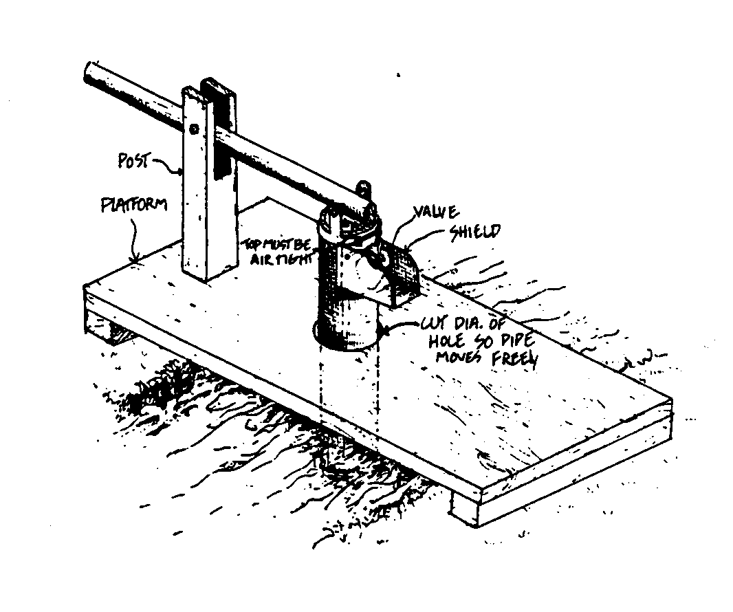
- Cover the pump stand with a removable cap of PVC, light sheet metal, or wood. Cut a slot in the cap just large enough to allow the movement of the pump rod. If desired, the pump may be sealed more closely by the addition of a flexible "stuffing": cut inner tube rubber or similar material to a disk that is slightly larger than the inside diameter of the pump stand. Cut a hole in the center of the disk that is just large enough to allow the passage of the pump rod. To assemble, slip the rubber disk over the last length of pump rod and fit it into the top of the pump stand. Put the cap into place with the pump rod poking out through the slot.
- Install the pump handle and connect the pump rod to the handle.
- Pump the well until the water is clear.
- Disinfect the well.
ASSEMBLY AND INSTALLATION OF THE SHALLOW WELL PUMP
The installation procedure for the shallow well pump depends on the type of well bore that exists. If the well bore is not much larger than the well pipe (a drilled or jetted well), installation is similar to the deep-well installation procedure. If the well bore is large (a dug well) then assembly and installation are different.
If the dug well is structurally sound and if the depth of water in the well is adequate, the pump and suction pipe are assembled and suspended in the well from the platform/well cover. An inlet strainer is generally not required.
A large community well may be covered and two or three or more pumps installed, depending on the demand on the well.
OPERATION AND MAINTENANCE
This pump does not require priming. Water should flow easily when the handle is pumped. Once or twice a week check to be sure that the pump action is smooth. Be sure the handle is not loose. Put a few drops of oil on the handle pins. There are only a few things that may prevent the pump from working well:
* worn piston leathers * worn or broken flap valves * broken or badly worn handle
Check these regularly and replace if necessary.
If the pump is not working properly, do not wait until it fails, but find out what is wrong and fix it promptly. This will keep downtime to a minimum.
The design of the pump is so simple that villagers in Thailand who do not have special equipment or tools have had no trouble making repairs and replacing worn parts. After varying periods of use, a survey found almost all the pumps in operation, with downtime for repairs less than 5%.
INERTIA PUMP
With only three moving parts, the inertia pump <see figures 1-5> is simple to
build and maintain. The design of the pump is unique: the entire pump moves up and down, rather than working parts inside. The pump can be made of sheet metal, as described here, or of PVC pipe or bamboo, although the bamboo may not last long.
The inertia pump is efficient for lifting water short distances, up to a maximum of about 4 meters. The capacity of the pump depends on its size and how fast the pump is moved up and down. The 8-cm version will lift 75 to 114 liters of water per minute a distance of 4 meters. The 15-cm version will lift 227 to 284 liters of water per minute a distance of 1 meter.
Dale Fritz, a long-time VITA Volunteer and a former staff member, developed the pump in Afghanistan in the mid 1950s. The pump has since been used by people all over the world.
MATERIALS AND TOOLS
Table 1: Materials (dimensions are given in centimeters)
Pump Diameter
8 cm 10 cm 15 cm
Galvanized sheet metal Shield, Part 2 43 x 30 49 x 30 61 x 21 Shield cover, Part 3 15 x 20 17 x 20 21 x 22 Top of pipe, Part 5 8 x 8 10 x 10 15 x 15 Pipe, Part 8 17 x 450 35 x 279 49 x 149 Spout 27 x 30 35 x 30 49 x 30
Barrel metal Handle bracket, Part 1 15 x 34 15 x 40 15 x 54 Valve bottom, Part 4a 6 x 6 8 x 8 12 x 12 Valve top, Part 4c 11 x 11 13 x 13 18 x 18
Wire Hinge, Part 4d 32 x 4mm dia.
Rubber, from inner tube Gasket, Part 4b 11 x 11 13 x 13 18 x 18
Table 2: Tools
Hammer Anvil (railroad rail or iron pipe) Saws, for metal and wood Tinsnips Soldering equipment Drilling tool and drills for wood and light sheet metal (or punch)
Table 3: Dimensions for three sheet metal pumps
Pump Diameter
Part Dimension 8 cm 10 cm 15 cm
Handle bracket, A 34 cm 40 cm 54 cm Part 1 B 24 30 44 C 3.5 5 8.5 D 7 10 17
Shield, E 43 49 61 Part 2 F 14 16 20 G 14 16 20 H 3 3 2.5 I 8 10 15 J 4 4 K 30 30 32
Shield cover, L 15 17 21 Part 3 M 20 20 22
Valve bottom, N 6 8 12 Part 4a
Gasket, O 11 13 18 Part 4b
Valve top, P 11 13 18 Part 4c
Hinge, Q 16 18 22 Part 4d
Top of pipe, R 8 10 15 Part 5 Handle, Part 6 Wooden pole, about 5 cm dia. by 2 m long
Post, Part 7 Wooden pole, about 12 cm dia. by 140 m long
Table 4: Lift and capacity for three sheet metal pumps
Pipe Diameter Pipe Length Height of Capacity in liters Lift per minute(*)
8 cm 650 cm 2 to 4 m 75 to 114 10 cm 400 cm 1 to 2 m 114 to 152 15 cm 300 cm 1 m 227 to 284
(*) At 1830 m elevation. Will be greater at lower altitudes.
CONSTRUCTION
Tables 1 and 3 give the dimensions for making this pump in three sizes. Table 4 shows the length of pipe needed for these three sizes, the height water can be lifted, and the amount of water that can be pumped.
The pump is made from the thickest galvanized sheet metal that can easily be worked by a tinsmith. Successful models have been made from 24- to 28-gauge sheet metal.
The pipe is formed and made airtight by soldering all joints and seams. The valve is made from the metal of discarded barrels and a piece of truck inner tube rubber. The bracket for attaching the handle is also made from barrel metal. The pump can be built easily by anyone used to working with sheet metal.
Cut the parts to the correct sizes taken from the tables. Assemble according to the drawings. The two larger pumps may need to be strengthened to prevent the pump body from collapsing if the pipe hits the side of the well. Do this by forming "ribs" about every 30 cm below the valve or by attaching bands made of barrel metal. The bands should be clamped around the pump body, using small bolts.
Smooth the pump handle at one end so it can be gripped easily. Make the supporting post about as high as a person's waist to make operation easier. Attach the handle to the pump and the post with 10 mm bolts or nails of about that size.
In making any of these pumps, the hole covered by the valve should have the same area as the pump body.
It is very important that the plug in the top of the pipe be made completely airtight.
To pump more water more easily, build two of the 8-cm models. Mount them about 1 meter apart on a pivot on a platform over the well. Connect the two pumps by a wooden beam wide enough for a person to stand on. Build troughs to catch the water as it pours out of the pumps. To use the pump, the operator stands on the beam, shifting his weight from side to side.
OPERATION AND MAINTENANCE
The pump must be primed, and the bottom of the pipe must be submerged far enough to develop the pull required to lift the water. For a lift of approximately 4 meters, for example, the pipe should extend into the water 1.5 meters. Check lengths in Table 4.
The pump works by suction. That is, it builds up a quantity of water within the cylinder. A particular rhythm is necessary to pump the water up and down. Using short strokes at the rate of about 80 per minute works best.
Otherwise, there is no real rule of thumb to guide the user, and some practice and "trial and error" experimenting is required.
With so few moving parts, there is little to wear out. The valve rubber will wear, however. Check it frequently and replace it if necessary. Periodically examine seams and joints for airtightness. Seal with solder if leaks develop.
Check pivots in the handle. These will wear over time and may cause too much play in the pumping action. If this occurs and the pump is in danger of damage from striking the side of the well, make a new handle. Be sure the holes for the pivot rods are the same size as the original, and not the new worn-out size.
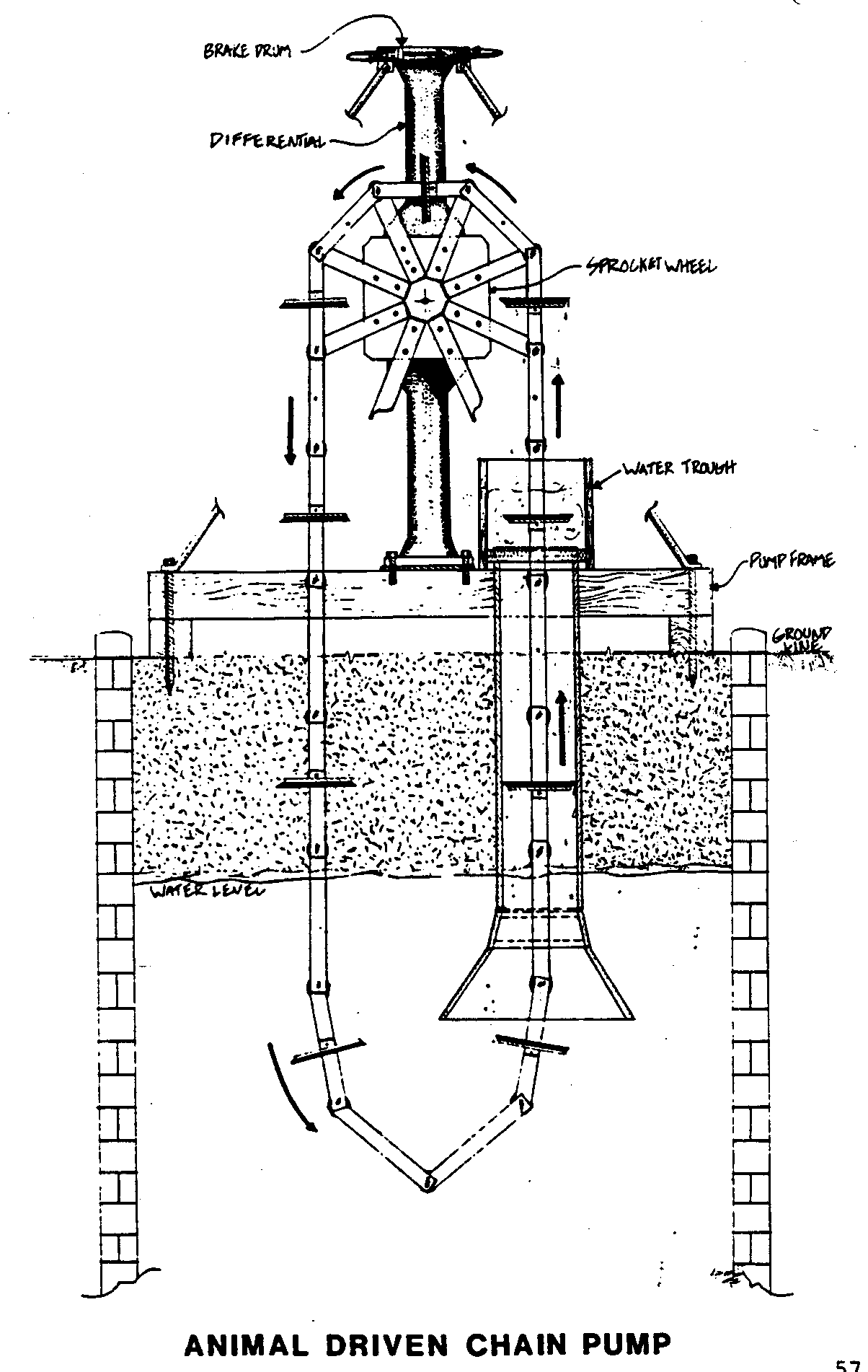
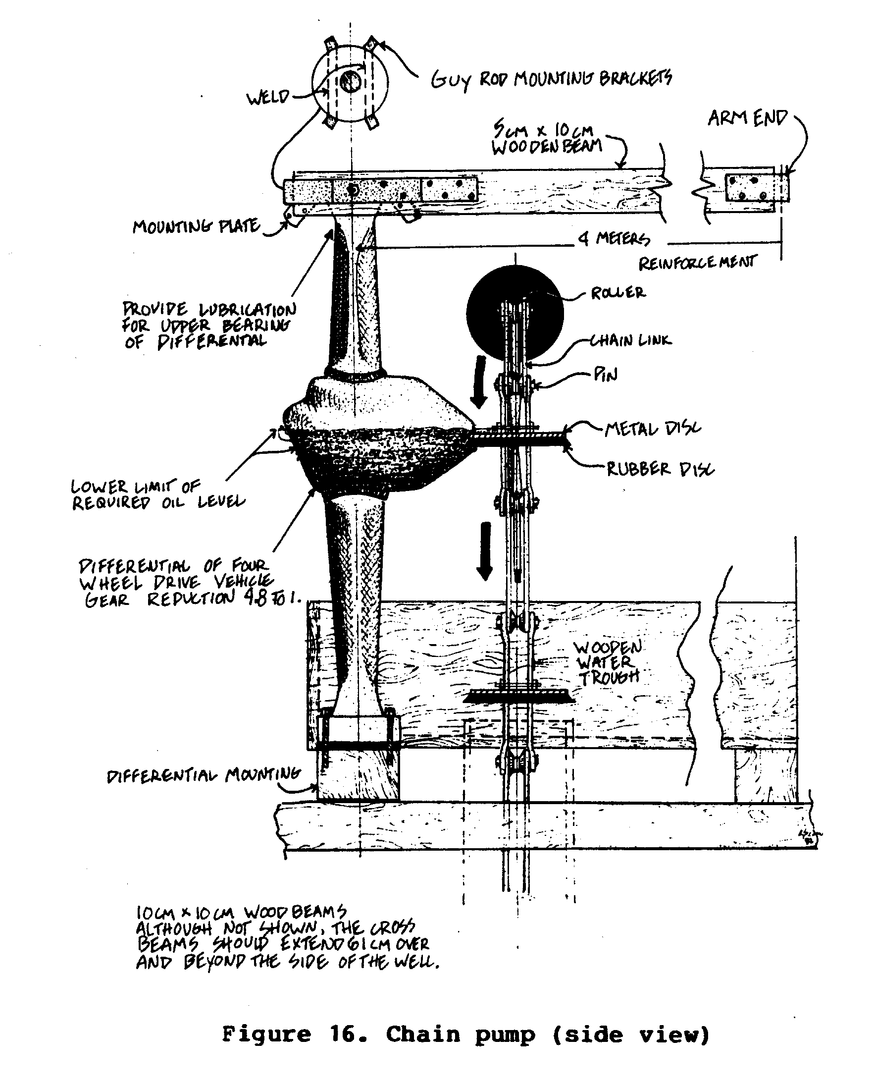
Chain pumps, which can be powered by people or animals, have been in use for centuries. The pump takes its name from the series of links and disks forming a continuous chain that pulls water up through a pipe as it passes around a sprocket wheel.
The pump presented here uses salvage auto parts, scrap metal, and heavy lumber. It was adapted by Peace Corps Volunteers in Chad from a basic chain pump that appears in VITA's Village Technology Handbook. It will lift water from depths of up to 6 meters (20 feet), it the rate of 8,000-9,000 gallons per hour.
This is the most expensive and complex of the pumps included in the manual. It also has the greatest potential output. Cost of the pump depends on the availability of salvage materials and can be reduced by substituting less expensive locally available materials where appropriate.
MATERIALS AND TOOLS
As shown in Figure 1, the finished pump frame is partially made of sawed lumber. If sawed lumber is not available in the area, logs can be used.
Torque arms also can be made from round poles or angle iron, depending on materials available. If the pump is to be moved from one well to another the logs should be kept between 7.5cm and 12.5cm in diameter. The frame and pump can be carried without a great deal of difficulty. Or, the pump assemblage can be pulled by an animal from one location to another.
Please note on the materials list that quantities are not shown for the rollers, chain links, disks, attaching pins, or rubber gasket material. These quantities must be calculated according to the depth of the particular well.
Note also that some parts can be made of wood instead of metal, if it is more readily available. These parts include the rollers, disks, and chain links.
These plans call for 15cm-diameter PVC pipe. Should a smaller or larger diameter pipe be used, it will be necessary to alter the size of the rubber gasket and the metal disk accordingly. The metal disk should be approximately 6 mm smaller in diameter than the inside diameter of the pipe chosen. The rubber disk, on the other hand, should be 3mm larger in diameter than the inside diameter of the pipe. A funnel-type apparatus is attached to the bottom of the PVC pipe to guide the chain and disks into the pipe. For a 15cm pipe the flared end of the funnel should be 36cm to 46cm in diameter.
MATERIALS:
- Four-wheel drive vehicle differential with brake drums attached.
- 8 steel arms 26.7cm x 5cm x 10mm thick steel plate
- 30.5cm x 30.5 x 6mm thick steel plate (hub)
- 5cm diameter steel or cast iron rollers(*)
- 26.7cm x 2.5cm x 6mm thick plate steel(*) (chain links)
- 14.6cm diameter steel disks 1.2mm thick(*) (18 gauge)
- 15.6cm diameter rubber gaskets 3mm thick(*) (made from old inner-tube)
- 10mm diameter steel rods 6.7cm long(*) (connecting pins)
- 7 - 35.6cm x 5cm x 5mm thick steel plates (torque arm reinforcement, arm end piece and mounting plates for guy rods)
- 4 - 3cm x 3cm x 3mm angle steel(*) (guy rods)
- Scrap steel plate and inner-tube rubber (enough to cover and seal bottom of differential housing)
- 1 gallon of motor oil (lubrication)
- Cotter pins(*) (2.5cm length)
- 24 bolts, 10mm x 2.5cm, with nuts (hub sprocket and guy rod assembly)
- 12 bolts, 10mm x 8cm, with nuts
- 4 bolts, 10mm x 14cm, with nuts (torque arm and bracket)
- 2 bolts, 13cm x 10cm, with nuts (torque arm)
- 6 - 13mm nuts
- 12 bolts, 10mm x 22cm, with nuts
(*) Depends on well dimensions or depth of well.
- 15cm diameter PVC pipe(*)
- Wood(*) (trough)
- 10cm x 10cm wood lumber(*) (frame)
- 2 - 5cm x 10cm x 4.5meters wood lumber (torque arms)
Miscellaneous - 10mm dia. nails, glue, metal clamps
TOOLS:
Hammer
Needle-nose pliers (fastening cotter pins)
Compass
Metal drill and bits
Metal hacksaw and blades
Ruler
Casting facilities (rollers)
Knife (to cut gasket materials)
Rivet machine
Pencil
Anvil (optional--read instructions)
Adjustable wrench
Welding equipment with cutting attachments (cutting steel plates)
CONSTRUCTION
This chain pump consists of four major components: 1) chain and disk assembly, 2) sprocket hub and arms assembly, 3) differential and frame assembly, and 4) torque arm attachment.
* Depends on well dimensions or depth of well.
I. Prepare the chain and disk assembly.
Determine the length of the chain. To do this, attach a large rock to a length of rope and lower the rock into the well until it barely reaches the bottom. The length of the rope indicates the depth of the well and provides a guide to the number of chain links, disks, and rollers needed. Because the chain is continuous, it has to be two times the depth measurement of the well plus-2.0m.
Figure 2 shows the dimensions of the chain links. To find the
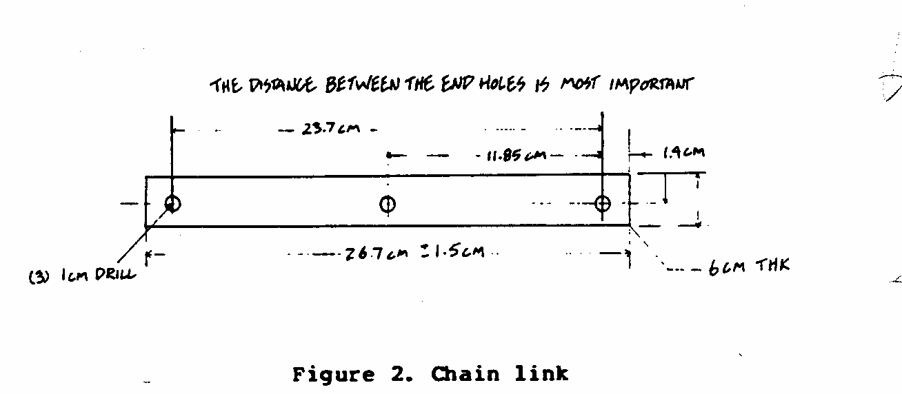
number of links needed for a given well, measure between the end holes (23.7cm) and divide this number into the total length of the chain needed. The result should be an even number; if odd, use the next lower even number.
Cut 6mm thick steel plate to the dimensions shown in Figure 2. Make two pieces for each section of chain link. Drill holes as indicated.
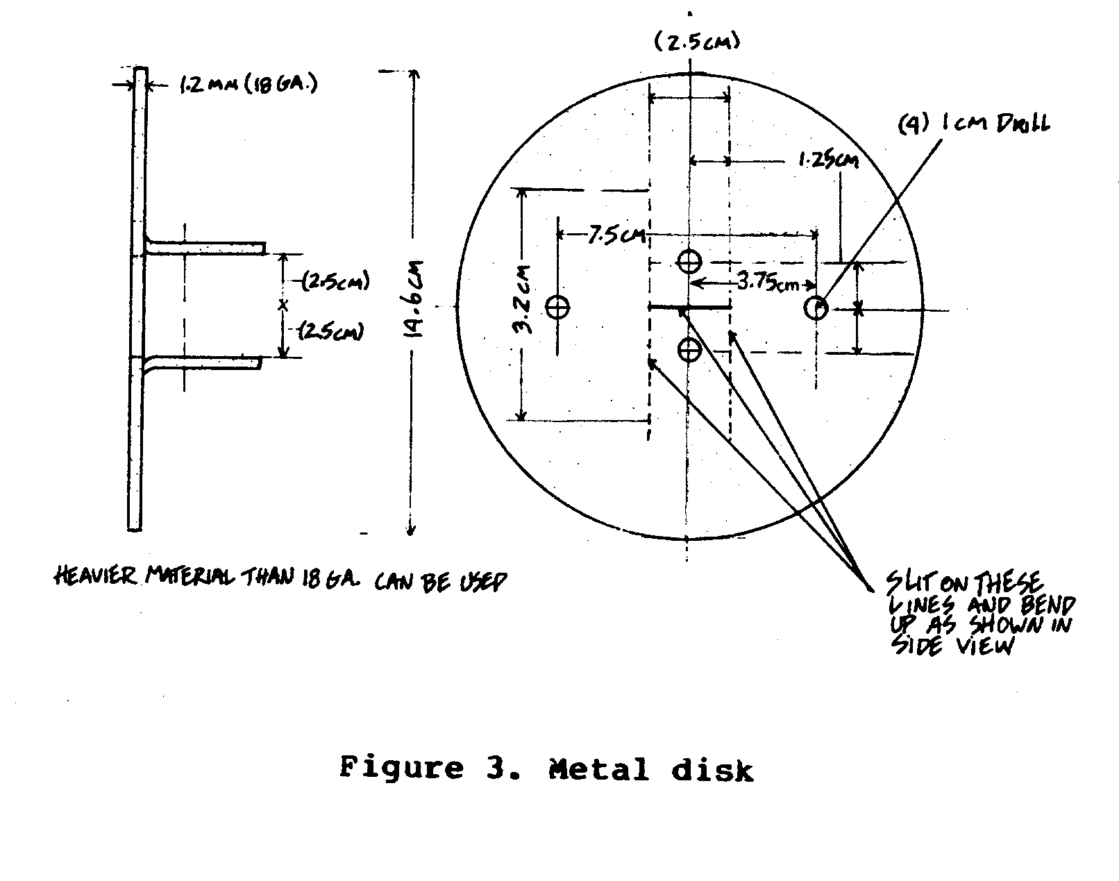
Determine the number of disks required by dividing the total number of links by two: there will be one disk for every two links in the chain. Figure 3 and 4 show the two disk components.

Figure 3 is a metal disk and Figure 4 is the rubber
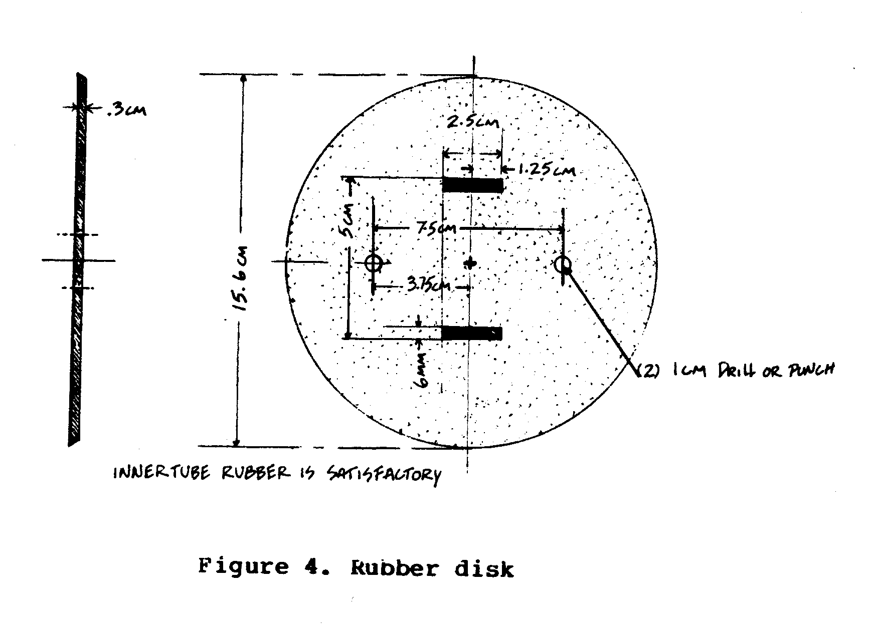
gasket.
Cut the rubber gasket carefully. It is better to start with the holes too small. If the holes are too large, water will escape between the chain link and the gasket.
Construct the required number of each component and set aside.
Make rollers. The number of rollers needed is equal to the number of links. The rollers are of steel or cast iron. If unavailable locally, it will be necessary to have them made. Dimensions for the rollers are provided in Figures 5 and 6.
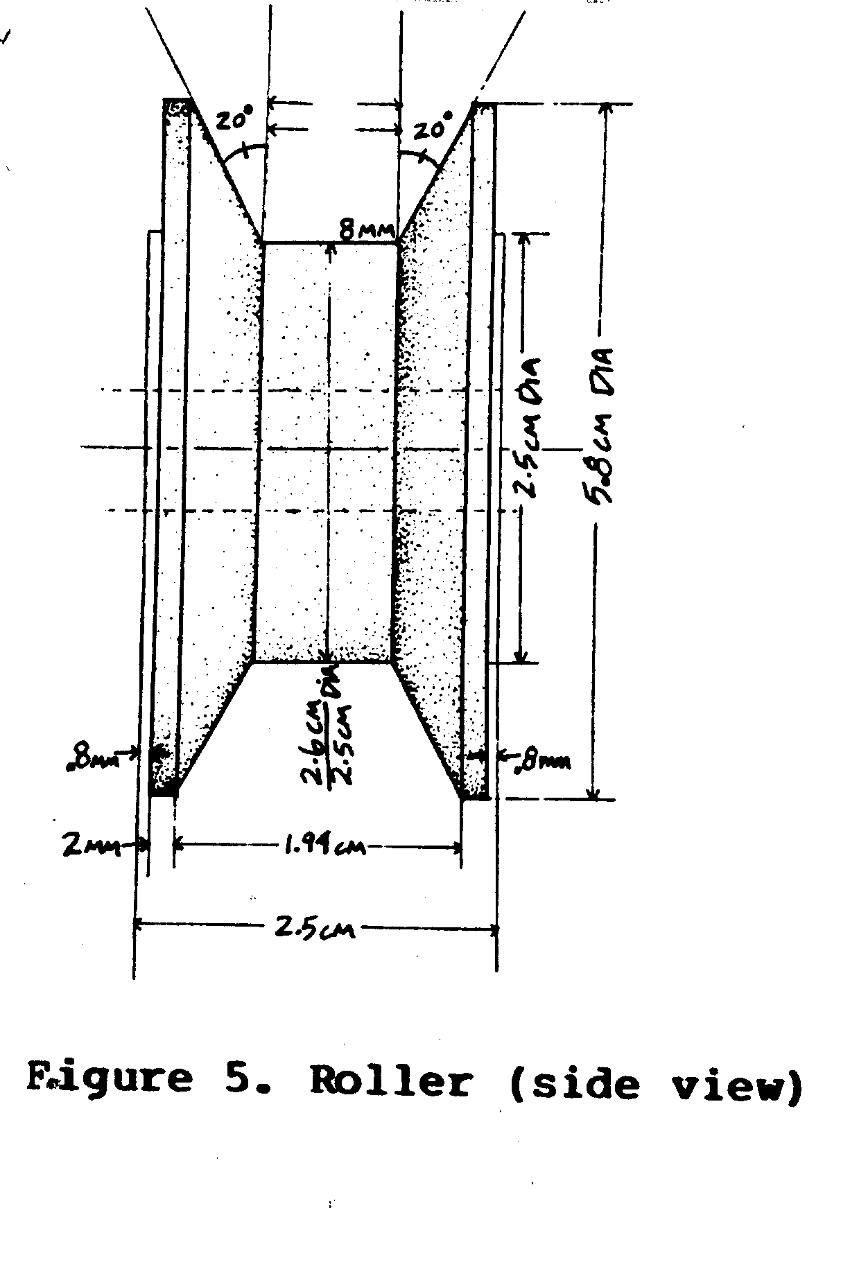
An alternative to the one-piece cast roller is a roller made of three wood or metal disks bolted together, as shown in Figure 7.
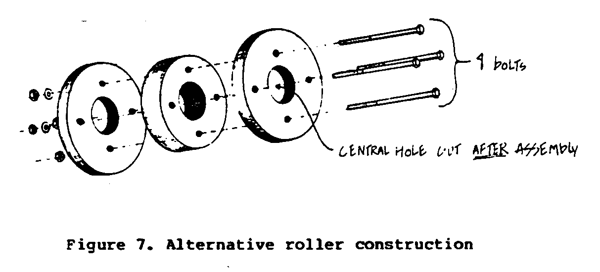
Dimensions should be approximately the same as the cast roller.
Make connecting pins. The number needed equals the total number of links and disks. Figure 8 shows the dimensions of the pins.
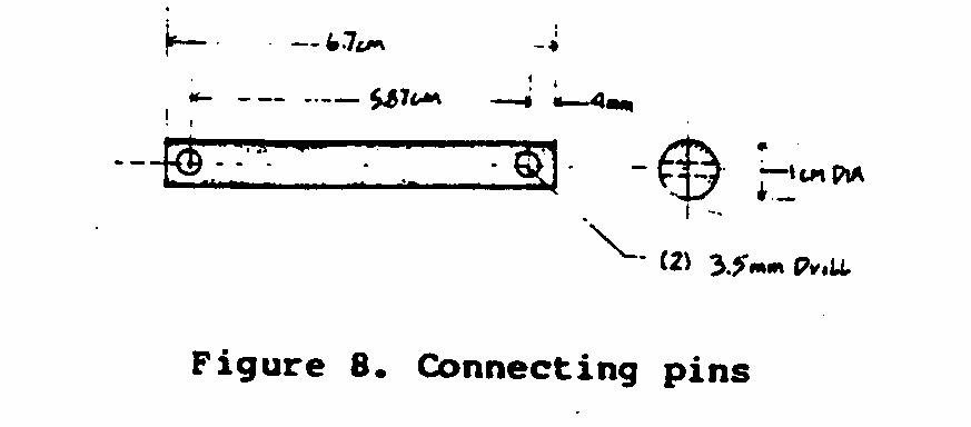
Drill two 3.5mm holes in each pin. The pins should be made from cold drawn steel rods for maximum life expectancy. Construct the required number of pins and set aside.
Assemble the chain as shown in Figure 9. Use the 6.7cm cotter
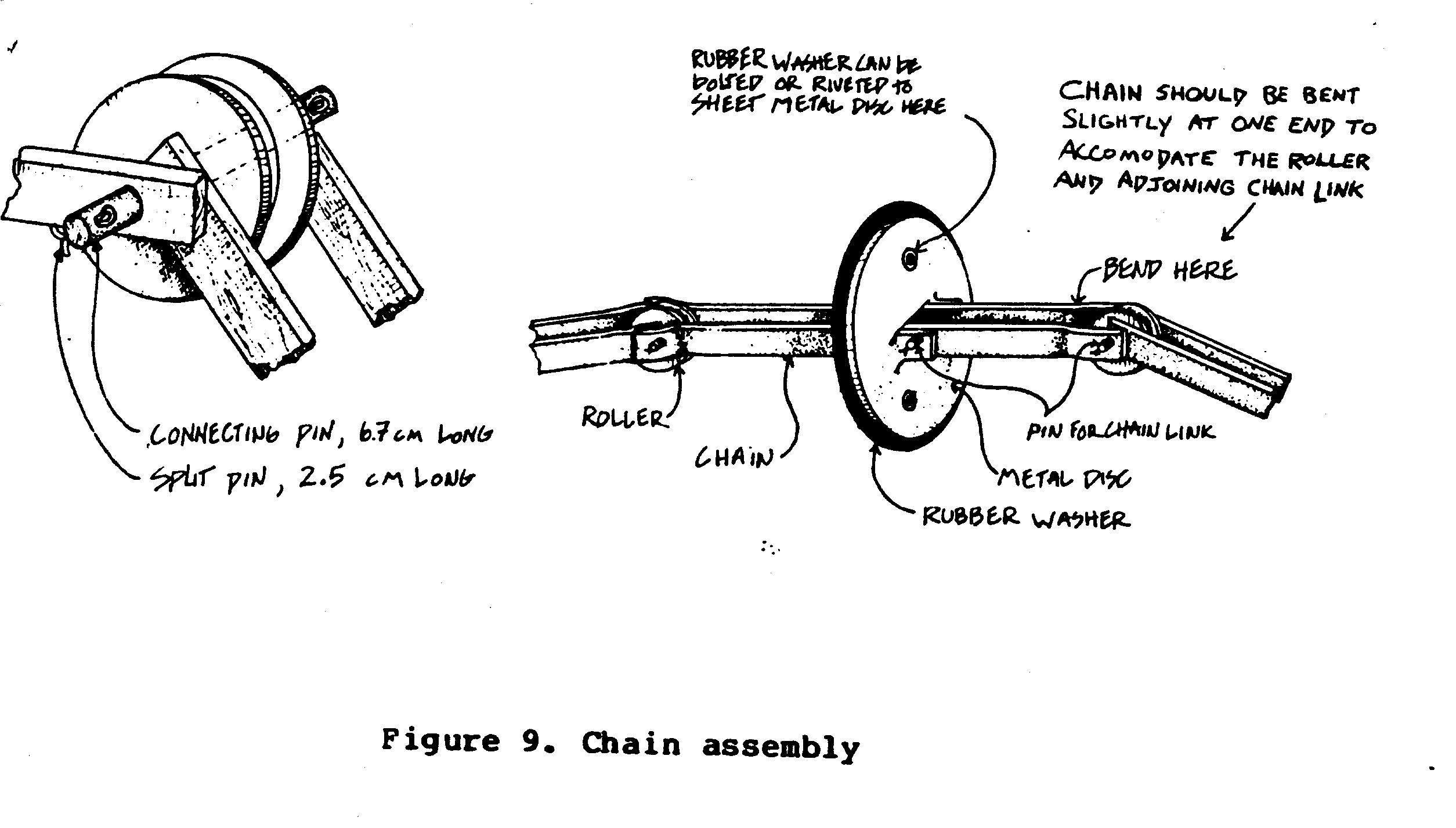
pins to fasten the disks and rollers to the chain link. Remember that the rubber and metal disks are attached to every other link. Do not fasten the last roller and chain link together: this will be done after the chain is pulled through the 15cm PVC pipe (see Figure 1).
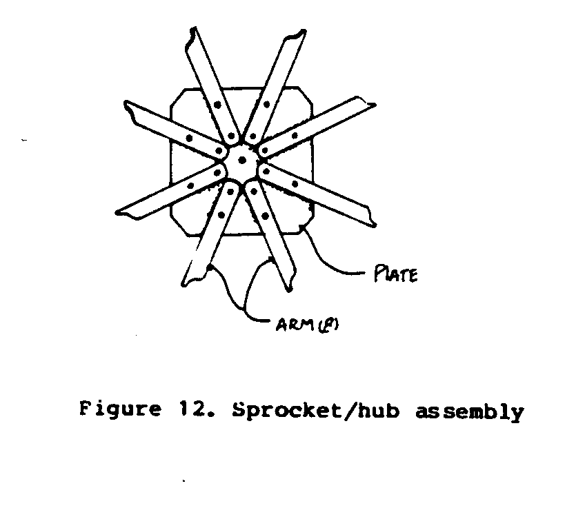
II. Prepare the hub sprocket assembly.
Construct hub plate from a 30.5cm x 30.5cm x 6mm steel plate, following the dimensions given in Figure 10. Follow the measurements
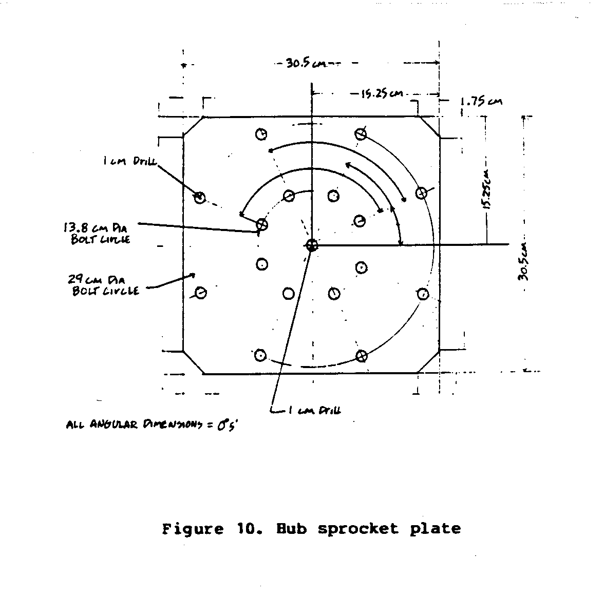
exactly. The easiest method of scribing a circle is with a meter stick, a nail, and a pencil. A 10mm diameter nail is nailed to one end of the meter stick; this point is the center of the circle. Measure from the nail the distance of the radius (half the diameter) and drill a hole to fit the pencil at this point. Drill a 10mm hole in the center of the steel plate. Put the nail in the hole and with the meter stick and pencil draw the two circles. Drill eight evenly spaced 1cm holes in each circle as shown.
Take scrap steel plate, 10mm thick; cut 8 arms to the dimensions given in Figure 11. The two holes and radius center line measurements must be exact for each arm.
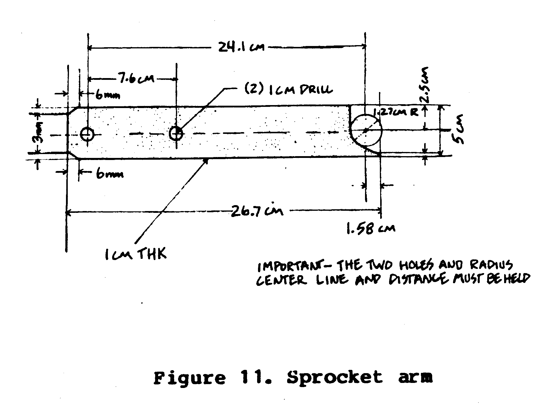
Attach the arms to the hub with 10mm x 2.5cm bolts and nuts. Be sure to insert the bolt from the back of the hub plate, through the arm section, before fastening with the nuts. <see figure 12>
III. Prepare the Frame
The frame is made from 3 wood beams 10cm x 10cm x 1.6 meters long and 2 beams of 10 cm x 10cm x [diameter of the well(s) + 1.25 meters].
The wood beams should be laid out as shown in Figure 13.
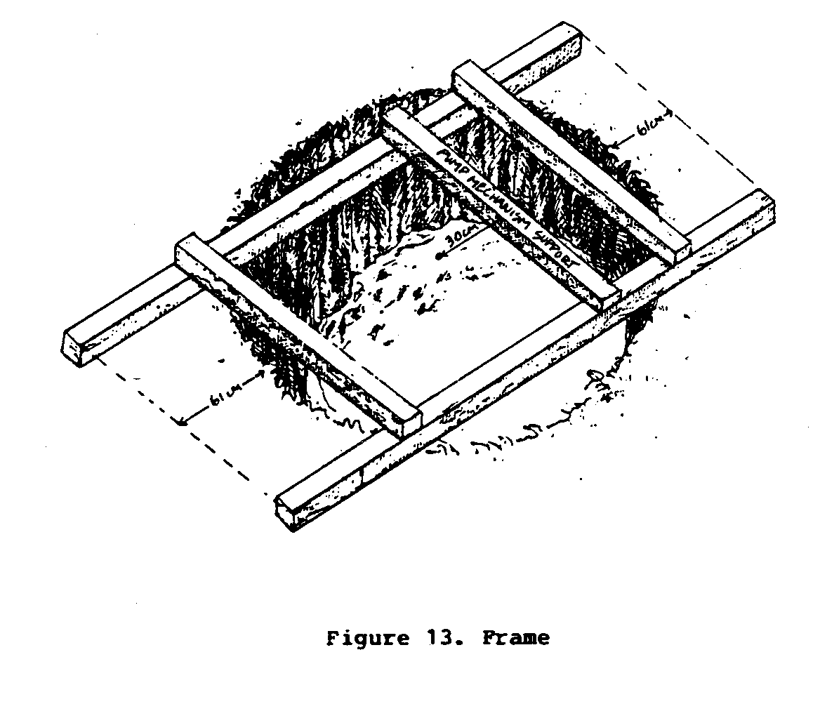
Make sure that the two bottom support beams extend at least 61cm beyond either side of the well. Mark board positions and remove from well.
The wooden beam that supports the pumping mechanism should be bolted to the bottom support beam 30cm from the center point of the well.
Using a wood drill, bore 10mm diameter holes. Fasten frame together with 10mm x 22cm bolts and nuts.
IV. Prepare the differential and frame assembly
<see figures 14 & 15>
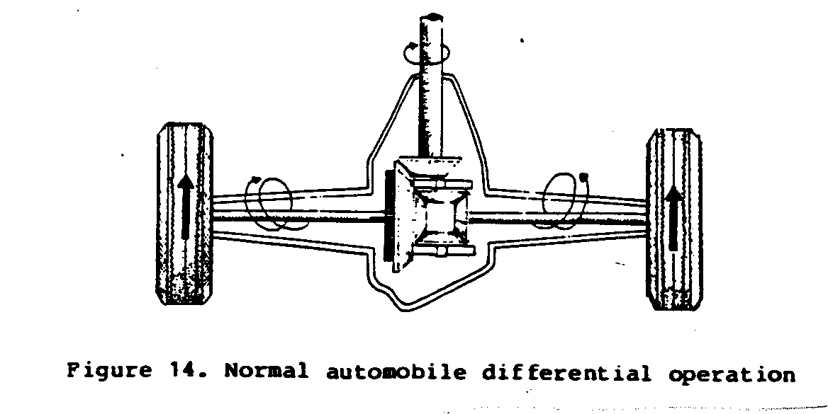
Remove one brake drum from the vehicle differential.
Cut out a rubber gasket and steel plate to cover the exposed end of the differential. Bolt into place, to keep oil from leaking out.
Jam the differential portion of the gearing by welding or by inserting a piece of metal secured with bolts so that it cannot be moved. It may be necessary to provide a means for putting oil into the differential, which is normally used in the horizontal position. (The flow of power is reversed from that which was initially intended; instead of the drive shaft turning the axle, the axle turns the drive shaft.)
Attach the sprocket hub to the flanged portion where the drive shaft normally fastens to the differential. The hub has a 10mm center hole; there will be a similar center hole in the drive shaft.
To center the sprocket hub on the drive shaft, place a pointed 10mm pin in the hole of the sprocket hub and the drive shaft center hole. Mark the hub plate so holes can be drilled for attaching the two. It may be possible to remove the inside arm bolts of the hub assembly and use those holes for attaching the hub to the flanged portion of the drive shaft. If this is not possible, drill new holes in the hub plate and flanged portion: in this case, use a minimum of four 13mm bolts. <see figure 16>
Make the guy rod mounting brackets: two (2) brackets have to be made and welded to the underside of the brake drum. <see figure 17>
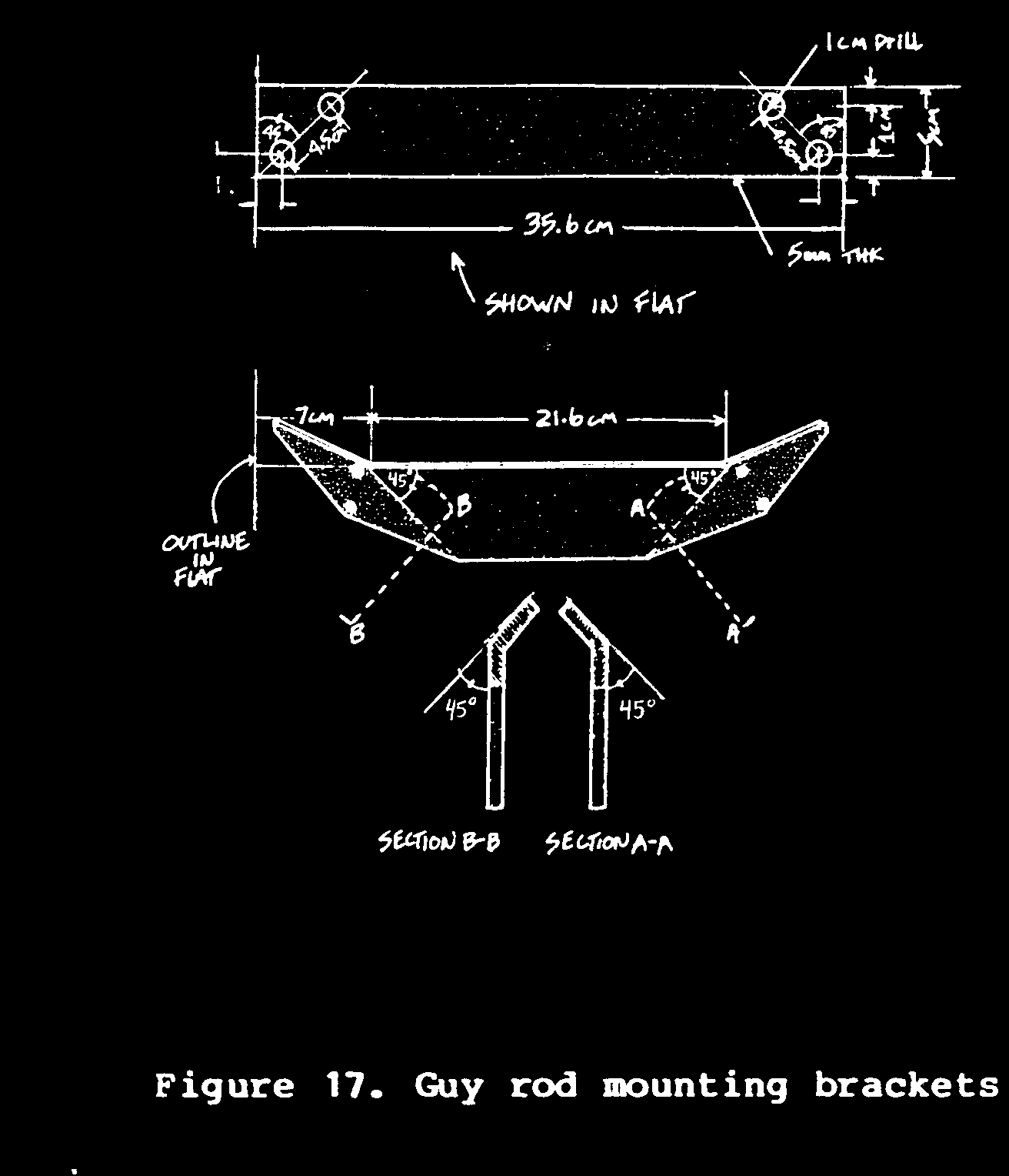
Figure 18 shows the arrangement of the guy rods that support
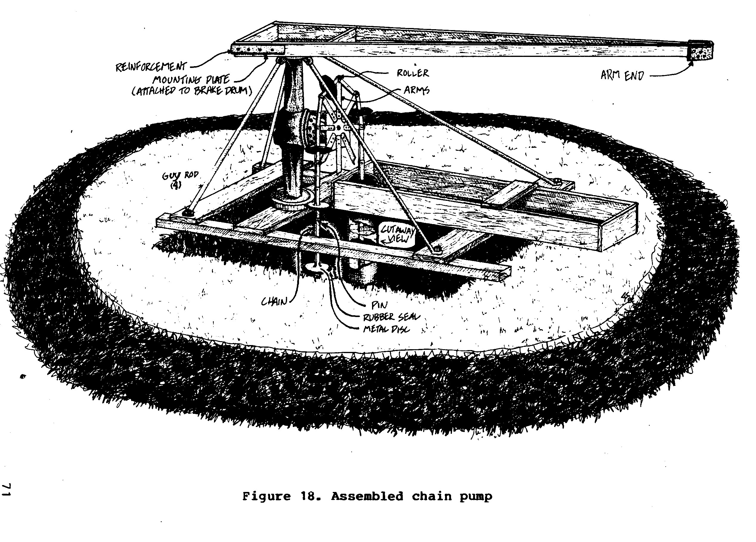
and stabilize the differential. Fasten the bottom of the guy rod to the wooden support members by removing from each corner of the frame one 10mm x 22cm bolt and nut. Re-insert the bolts through the guy rods and then through the wooden members. Fasten securely. Bolt the upper ends of the guy rods to the mounting brackets on the brake drum.
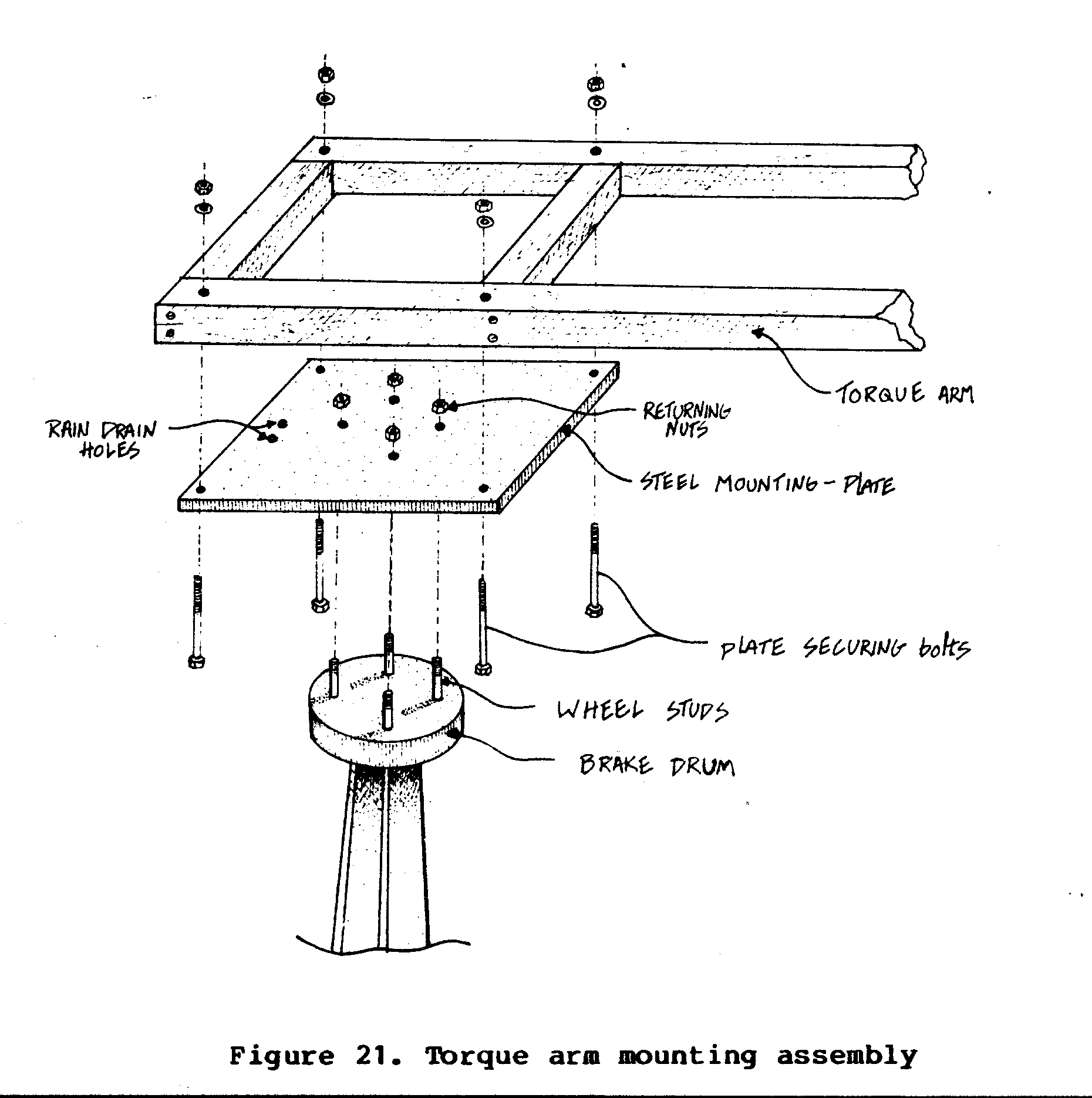
V. Assemble the Torque Arm
Use scrap steel plate 5mm thick to make four reinforcing plates
Attach one to each side of both torque arms (5cm x 10cm x 4.5m wood lumber) where they straddle the brake drum. Each torque arm is attached to the brake drum with 1.3cm diameter bolts as shown in Figure 20.
Drill two 1.3cm holes in the revolving part of the brake drum perpendicular to each other.
Use two 1.3cm nuts between the torque arm and the brake housing; these nuts serve to offset the stress of the torque arm on the brake housing. (See figure 21)
Construct the torque arm end bracket as shown in Figure 22.
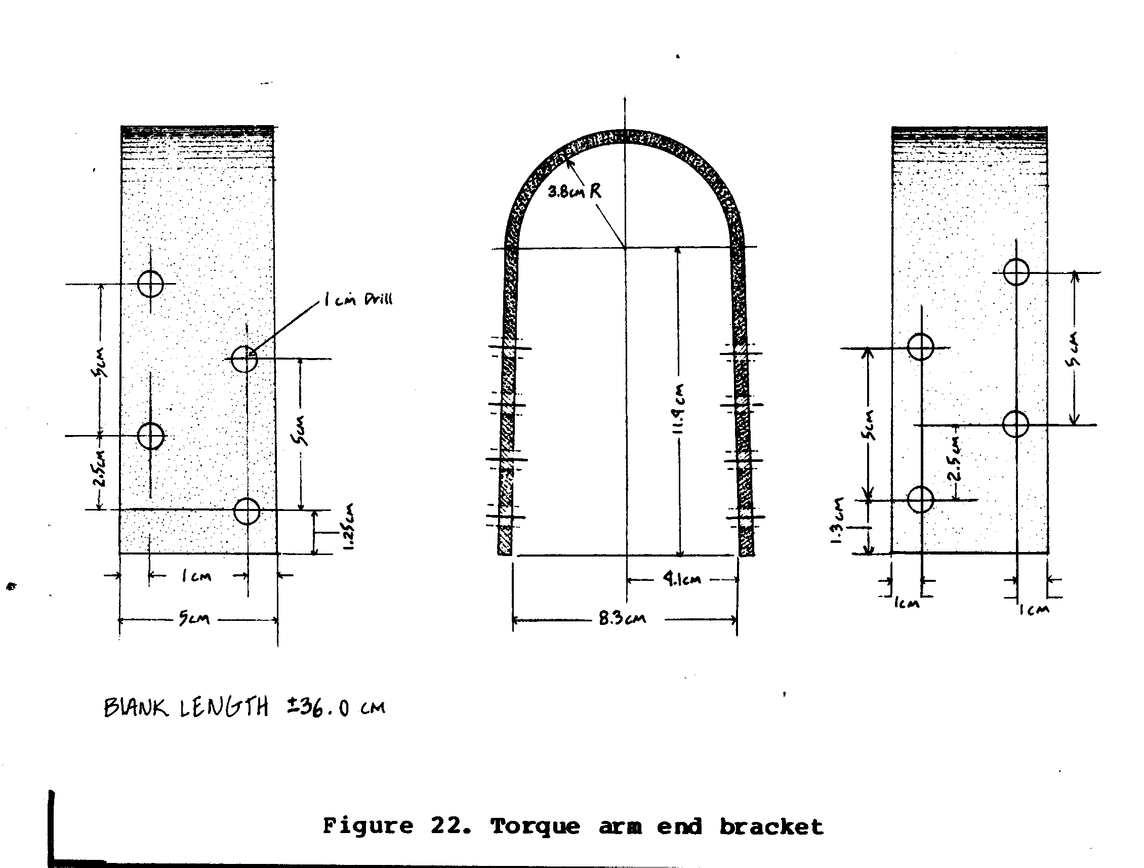
This bracket serves to attach the two torque arms together and provides a means of hitching the animal. Be sure to drill through both (5cm x 10cm) wood members. Insert 1cm x 12cm bolts through one side of the metal bracket, through the wooden members and then through the corresponding side of the metal bracket before fastening.
VI. Attach Water Trough
Attach the water trough and 15cm diameter PVC pipe. Figure 23
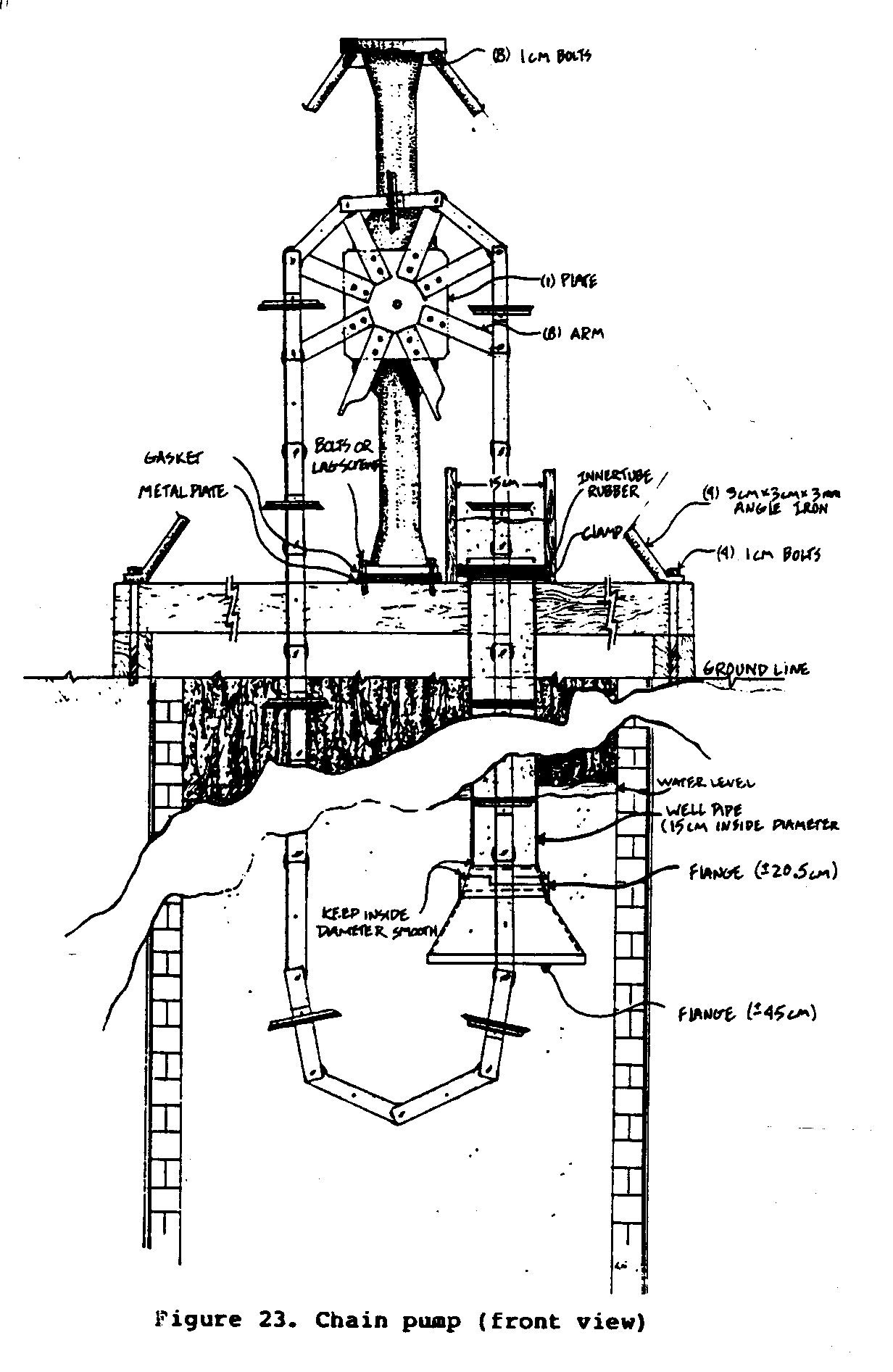
shows the arrangement of the pipe and water trough. The bottom of the PVC pipe, which is at least 20cm below the water line, is flared to allow easy entry of the disks as the water is pulled up the pipe. The bottom section of the flare should be 2-1/2 to 3 times the diameter of the PVC pipe. The flared sections can be made of 18 gauge (1.2mm) steel sheeting. The inside surface should be as smooth as possible where it joins the 15cm pipe. Otherwise the rubber disks will wear out quickly.
The top of the 15cm PVC pipe enters through the bottom of the wooden water trough, where it is clamped both under the trough and on top to keep the pipe from being pulled through the trough when the pump is operating. Inner-tube rubber or scrap pieces of 15cm PVC pipe can be used as reinforcing material under the metal clamps.
Nail or bolt the water trough to the wooden frame supports, the differential, and also to the wood cross member located on the outer perimeter of the well (see Figure 18). A metal water
trough can be substituted for the wooden one if you prefer. The extra expense will assure a longer life and less chance of leakage problems.
OPERATION AND MAINTENANCE
Before installing the pump in the well it is necessary to connect the disk/chain link assembly. Pass the disk/chain links through the 15cm PVC pipe with the rubber side of the disk up.
The following procedures should be carried out in order to keep maintenance at a minimum:
- Make sure there is enough oil in the differential at start-up.
- Check oil level monthly.
- Check drive shaft/sprocket hub every day for oiling needs. Dust accumulation tends to dry up the oil quickly.
- When the pump sits for a time without being used, the rollers tend to freeze up and need to be oiled and tapped loose.
- Check the rubber disks after about 250 hours of use and replace them, if necessary.
Prepare the track for the animal to prevent slipping (loss of traction). Use a layer of gravel, straw, twigs, wood or bark chips, or whatever is available. Slope the track slightly away from the well to prevent drain-off of waste products into the well.
It is best that the animal pull the torque arms instead of pushing them because the weight of the water forces the pump to run in reverse when the animal stops walking and could cause injury to the animal. An animal can be expected to run the pump an average of 4 to 6 hours per day without undue fatigue. ARCHIMEDES SCREW
There are many situations in which water for irrigation needs to be lifted only very short distances from a river or canal to the fields. To accomplish this, farmers in ancient times adapted a device said to have been invented by Archimedes to remove water from the hold of a large ship. The device is the Archimedes screw, a helical channel arranged around a central crank shaft. The screw can be made in a variety of ways, from continuous tubing wrapped around the shaft to a spiral series of overlapping boards or plates within a cylinder. Depending on the design, the screw can be used for such diverse purposes as lifting water or loading grain.
The Archimedes screw presented here <see image> a water lifting device.
It consists of a wooden cylinder wrapped around a spiral of overlapping boards. The central shaft is of metal pipe or rod. The screw is turned by hand, or can be attached to a windmill. It is capable of lifting approximately 100 gallons of water per minute to a height of 18-20 inches. It can be moved easily from place to place as needed. Screws of this type are still used daily by Egyptian farmers along the Nile. This particular variation was built and tested by Loren Sadler and the VITA design group at the Sperry-New Holland Corp.
MATERIALS AND TOOLS
MATERIALS:
For a typical Archimedes Screw lifting 100 gallons per minute a vertical distance of 20 inches:
1 - 90" long, 1" diameter pipe or 3/4" diameter rod for the crank shaft
142 - 18" long boards, 1-1/2" wide x 1/2" thick for the spiral (Cut carefully. Inaccurate lengths reduce efficiency of the screw.)
40 - 71" long boards, 1-1/2" wide x 1/2" thick for wrapper around spiral (An alternate wrapper may be one piece of light sheet metal 62" x 71" or two pieces, each 36" x 62". )
6 - Bands of sheet metal, wire, etc. about 62" long to tighten wrapper around spiral
TOOLS:
Saw Drill Hammer and/or screwdriver Plane Screws, nails, waterproof glue for fixing boards in position
CONSTRUCTION
Drill a hole for the crank shaft at the center of each of the 142 boards. The accuracy with which these holes are drilled influences the efficiency of the Archimedes Screw. Attach the first board to the crank shaft as shown in Figure 2. Fix the
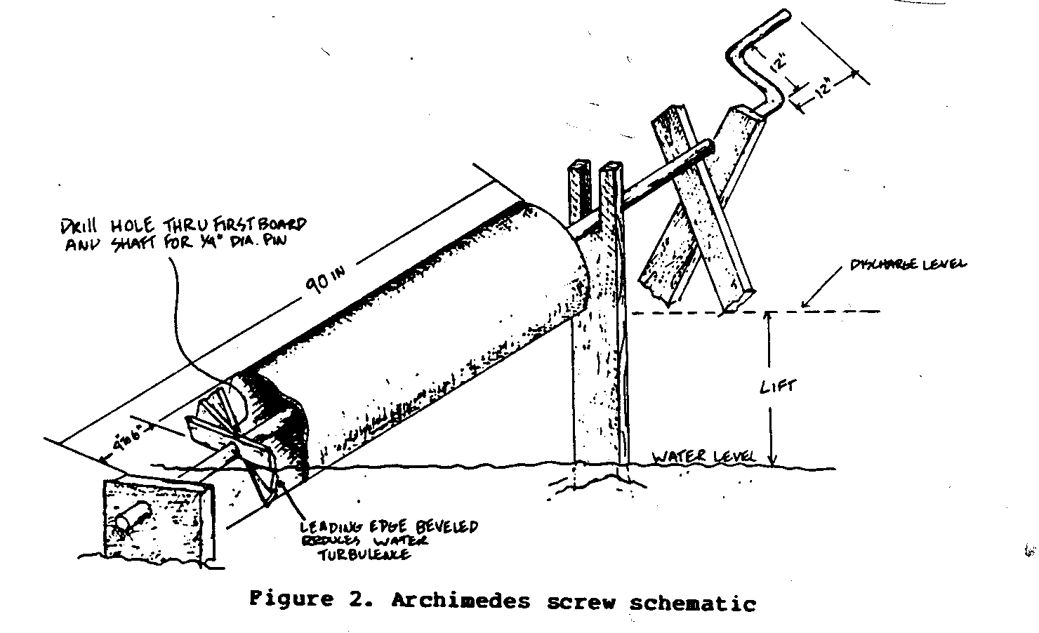
second board to the first board by several screws or other means, with opposite corners of the two boards aligning. Install the remaining boards in the same manner. Attach the last board to the crank shaft in the same manner as the first. Bevel the leading edge of each board in the spiral so that water will flow over it more easily. Seal the spiral with tar or pitch to improve watertightness.
Next install the wrapper, forming it tightly around the spiral to minimize water leaks. If the boards are used, they should be beveled for a tighter fit with each other. Seams in sheet metal should be sealed carefully to prevent leaks. Cut away the lower (intake) end of the wrapper at the start of each side of the double spiral so that water may be scooped up as the spiral turns. Fasten metal bands or wires tightly around the wrapper. Attach drive crank.
Seal joints in wrapper with tar or pitch. Prepare supports for the screw as illustrated, using any available suitable materials. Wooden bearing blocks should be soaked in oil to prolong their useful life.
Construction Variations
Archimedes Screws of this design may be built in a variety of sizes.
For best results, Keep the lift height at 1/3 or less of the screw length. For economical construction and good performance, the width of the boards used for the spiral should be between 3 and 4 times their thickness. The number of boards required for a spiral will be approximately 3 times the lift height divided by the board thickness plus 1-1/2 times the board length, as in the formula:
3H - (N = T + 1-1/2 BL)
Performance Evaluation
Several Archimedes Screws of this design have been constructed and tested. Archimedes Screws observed in Egypt and India have the following specifications and performance data: (*)
Length Diameter Lift Capacity H.P. (ins.) (ins.) (ins.) (gpm)
61 22 10 132 .128 81 19 20 100 .042 100 16 30 66 .042 73 16 18 66 .025
(*) Water Lifting Devices for Irrigation, FAO Agricultural Development Paper #60.
OPERATION AND MAINTENANCE
Put the screw into place, with the lower end in the water that is the source of supply. Turn the crank to lift the water to the irrigation channel.
Check the screw periodically to be sure boards remain fastened securely. If necessary, tighten the metal bands or wires. Check the support posts for wear and soundness; replace if necessary.
Though no accurate figures are available, a screw of this type should provide many years of service.
CONVERSION TABLES
Units of Length
1 mile = 1760 yards = 5280 feet 1 kilometer = 1000 meters = 0.6214 miles 1 meter = 3.2808 feet = 39.37 inches 1 mile = 1.607 kilometers 1 foot = 0.3048 meters 1 inch = 2.54 centimeters 1 centimeter = 0.3937 inches
Units of Area
1 square mile = 640 acres = 2.5899 square kilometers 1 square kilometer = 1,000,000 square = 0.3861 square meters miles 1 acre = 43,560 square feet 1 square foot = 144 square inches = 0.0929 square meters 1 square inch = 6.452 square centimeters 1 square meter = 10.764 square feet 1 square centimeter = 0.155 square inches
Units of Volume
1 cubic foot = 1728 cubic inches = 7.48 U.S. gallons 1 British imperial gallon = 1.2 U.S. gallons 1 cubic meter = 35.314 cubic feet = 264.2 U.S. gallons 1 liter = 1000 cubic = 0.2642 U.S. centimeters gallons
Units of Weight
1 metric ton = 1000 kilograms = 2204.6 pounds 1 kilogram = 1000 grams = 2.2046 pounds 1 short ton = 2000 pounds
Units of Pressure
1 pound per square inch = 144 pounds per square foot 1 pound per square inch = 27.7 inches of water(*) 1 pound per square inch = 2.31 feet of water(*) 1 pound per square inch = 2.042 inches of mercury(*) 1 atmosphere = 33.95 feet of water(*) 1 atmosphere = 14.7 pounds per square inch (PSI) 1 foot of water = 0.433 PSI = 62.355 pounds per square foot 1 kilogram per square = 14.233 pounds per square inch centimeter
1 pound per square inch = 0.0703 kilograms per square centimeter
(*) at 62[degrees] Fahrenheit (16.6[degrees] Celsius)
Units of Power
1 horsepower (English) = 746 watts = 0.74b kilowatts (KW) 1 horsepower (English) = 550 foot pounds per second 1 horsepower (English) = 33,000 foot pounds per minute 1 kilowatt (KW) = 1000 watts = 1.34 horsepower (English) (HP) 1 horsepower English) = 1.0139 metric horsepower (cheval-vapeur) 1 metric horsepower = 75 meters x kilogram/second 1 metric horsepower = 0.736 kilowatts = 736 watts
REFERENCES AND RESOURCES
Animal-Drawn Agricultural Implements, Hand-Operated Machines and Simple Power Equipment in the Least Developed and Other Developing Countries--Report of a Manufacturing Development Clinic, New Delhi, India: 21-30 October 1974, United Nations Industrial Development Organization, Geneva, Switzerland, Report ID/148 (IC/WG. 193/3), 1975. 45 pp. Includes recommendations that the governments of developing countries promote the local manufacture of agricultural machinery and implements. Includes lists and photographs of agricultural implements and the developing countries in which they are used.
Animal-Driven Power Gear, Geneva, Switzerland: United Nations, Publication GE .75-14371, 1975. 30 pp. The animal-driven power gear described in this publication works on the same principle as a bicycle. The device is basically an arrangement of levers and gears that transforms slow leg movement into the speedy rotation of a wheel. The output gearing provides up to 135 revolutions per minute--enough for operating a variety of individual processing machines. No technical drawings but does include photographs.
Corcoran, Tom. "Chad Chain Pump." Peace Corps Tech Notes (August 1969), pp. 8-9. Washington, D.C.: ACTION/Peace Corps. Gives drawings and explanation on initial Peace Corps work on modifying the VITA chain pump to use animal power. It is good background material but does not include good working drawings.
Effective Use of Animal Power on Farms Can Lead to Less Work and More Harvest. Oklahoma City, Oklahoma: World Neighbors, Vol. 11, #1E, 1979. 8 pp. Includes a very good section on training animals for farm use.
Chulalongkorn University Faculty of Engineering. The Development of a PVC Handpump. Bangkok, Thailand: Report submitted to the World Health Organization, 1981. 52 pp. A PVC suction type handpump, based on VITA designs, and fabricated by the Agricultural Engineering Division of the Chulalongkorn University, was tested and evaluated under laboratory conditions. Project had three phases: Phase I studied and modified the existing suction type PVC handpump for use in dug wells with a water level not deeper than 6 meters. Phase II developed a lift type PVC handpump suitable for dug wells deeper than 6 meters. Phase III modified the Phase II handpump into a small diameter tube well for use up to 30 meters. This pump uses PVC well casing as the pump cylinder. The new pump, which uses the Korean type piston, is recommended for all types of PVC handpump use in Thailand.
Hand Pump Testing and Evaluation to Support Selection and Development of Hand Pumps for Rural Water Supply Programs. Leidschendam, the Netherlands: World Health Organization International Reference Centre for Community Water Supply, 1979. 54 pp. A report of an international meeting, gives results of a survey of hand pump testing and evaluation projects. Guidelines for hand pump testing and evaluation are also given.
"How to Make a Hand Pump for Irrigation." Link, no. 26, pp: 20-29. Marshalltown, South Africa: Link. Sept. 1981. Simple instructions accompany illustrations that show how the hand pump works to lift water, the components of the pump, and how some of the component parts are made and fitted together. For complete plans, one can write to Link.
Islam, S.; Mazed, M. A.; and Roy, K. S. "Comparative Performance of Different Types of Manual Pumps," Agricultural Mechanization in Asia (Summer 1981), pp. 65-68. Tokyo: AMA. Looks at a collection of manually operated pumps that are used for irrigation, and compares capacity, lifting head, ergonomics, cost benefit ratio, and maintenance characteristics.
Kingham, John, et. al. Hand/Foot Operated Water Pumps for Use in Developing Countries. Report submitted to CA Testing and Research, Harpenden, United Kingdom, October 1980. 78 pp. Describes a project in which 12 brands of hand/foot operated deep well force pumps being used in developing countries were tested under laboratory conditions. This is a final summary of important features discovered during the tests and a discussion of the pumps, together with recommendations.
Kukielka, Boleslaw Jan. Interim Report on Drinking Water Protected Dugwell Programme in Four Pilot Project Districts in Thailand. Bangkok, Thailand: report presented to the Environmental Health Project, Department of Health, 1980. 21 pp. Results of a project to improve the drinking water supply of several Thai villages. Protected dugwells were built and inspected, and villagers were encouraged to install the wells and simple pumps themselves. Includes 11 technical drawings of piston rod assemblies and piston valve assemblies.
Laboratory Tests on Hand Operated Water Pumps for Use in Developing Countries. Washington, D.C.: International Bank for Reconstruction & Development/The World Bank. February 1982. 123 pp. Describes laboratory tests of 12 hand pumps. The long range objective of the program is to promote the manufacture of improved or more reliable hand pumps in developing countries, pumps that can be maintained by trained village operators.
"Linking Pumps for Better Performance," Basics, no. 7, p. 9. Sommerset, England: Basics, Rural Communication. March 1979. Includes a design for a simple frame that links two lift pumps and enables a single operator to work the two at the same time using his feet. This is less tiring and, because two pumps are working, provides a greater and continuous flow of water up to 3,500 gallons per hour). The diagrams show how the pumps are linked.
List of Agricultural Equipment and Tools for Farmers Designed for Local Construction. London: Intermediate Technology Development Group. Essentially a publications list of agricultural equipment plans available from ITDG.
McGrath, Patrick, et. al. A Hand Pump Primer. College Park, Maryland: University of Maryland, College of Engineering, 1978. 20 pp. A guide to the selection of appropriate hand pumps for given areas.
Pacey, Arnold. Hand Pump Maintenance and the Objectives of Community Well Projects. Oxford, United Kingdom: OXFAM, 1976. 21 pp. A consideration of the broader aspects of village pump maintenance. Suggests that community awareness and control of the pumps are essential if they are to be kept working. Also includes a list of hand pump manufacturers in India and some African and Western countries.
Simple Bullock-Drawn Implements for Efficient Irrigation. University of Udaipur, College of Agriculture, Jobner (Ext. Bulletin #1), 1964. 15 pp.
Sternberg, P. M.; Silver, M.; and Allison, S. V. "Flow Meter for Measuring the Discharge of Small Pumps," Appropriate Technology. Vol. 9, no. 1, pp: 14-15. Forest Grove, Oregon: Appropriate Technology, June 1982. Discusses conventional methods of flow measurement and calibration procedure and concludes that the hole-in-the-bucket meter is sufficiently accurate.
Sternberg, Yaron, and Knight, Robert. Development of PVC Well Screens for Local Fabrication in Developing Countries. Washington, D.C.: International Bank for Reconstruction and Development/The World Bank, April 1978. 8 pp. Describes the development of a well screen that can be made in most developing countries.
VITA. "Chain Pump for Irrigation (Hand Powered)," Village Technology Handbook, pp. 92-96 (Drawings and instructions). Arlington, Virginia: VITA, 1963. This section of the VTH describes basic concepts from which the animal powered chain pump was designed. Includes step-by-step construction details.
VITA. Construction and Maintenance of Water Wells. Arlington, virginia: VITA, 1969. 170 pp. Publication written for U.S. Peace Corps Volunteers who were employed to develop the ground water resources in the areas to which they were sent. It gives a general review of ground water, its occurrence and properties; well construction methods by digging, driving, drilling, and jetting; well liners; boring equipment; etc. It has a useful section on well pumps and also on the planning aspects of a well digging program, ground water exploration, choice of supplies, well protection without expensive equipment. It contains working drawings of tools, lists of parts needed, and step-by-step instructions. Techniques for drilling boreholes are given more attention than those describing hand dug wells.
Watt, S. B.; and Wood, W. E. Hand Dug Wells and their construction. London: Intermediate Technology Publications Ltd., 1977. 253 pp. Provides step-by-step guidance on the actual technique of hand dug well construction in which the shaft is large enough to permit the diggers to descend as the work progresses. The borehole method is not dealt with.
APPENDIX I
DECISION MAKING WORKSHEET
If you are using this manual as a guideline for including a simple-pump in a development effort, collect as much information as possible and, if you need assistance with the project, write VITA. A report on your experiences and the uses of this manual will help VITA both improve the book and aid other similar efforts.
Volunteers in Technical Assistance (VITA) 1815 North Lynn Street, Suite 200 Arlington, Virginia 22209-2079 USA
CURRENT USE AND AVAILABILITY
* Describe current agricultural and domestic practices that rely on water at some point.
* What water sources are available? Include rivers, streams, lakes, ponds. Are there wells in the area? What type? What are they used for?
* What is water used for traditionally?
NEEDS AND RESOURCES
* Based on current agricultural and domestic practices, what seem to be the areas of greatest need? Does the community need a source of clean drinking water? Would a reliable source of irrigation water stretch the growing season, permitting production of an additional crop for home use or sale?
* What are the characteristics of the problems? Is the local population aware of the problem/need? How do you know?
* Has any local person, particularly someone in a position of authority, expressed the need for or interest in this technology? If so, can someone be found to help introduce the technology?
* Are there local officials who could be involved and tapped as resources?
* How can you help the community decide which technology is appropriate for it?
* Which available water sources seem to be most useful? Is ground water sweet or saline? Will you rely on existing wells or will new ones have to be dug? How does the water table fluctuate? Who owns the well, or the land where new wells will be located? How do you gain access?
* Are construction materials available locally? Are local skills sufficient? Who will maintain the equipment? Are spare parts available if they must be purchased?
* Do a cost estimate of the labor, parts, and materials needed. Will health benefits of a sanitary well outweigh costs? Will improved agricultural yields pay for pump installation? Is a user fee an option?
* Does the technology require outside funding? Are local funding sources available?
* What is your schedule? Are you aware of holidays and planting or harvesting seasons that may affect timing?
* How will you spread information on, and promote use of, the technology?
IDENTIFY THE MOST APPROPRIATE TECHNOLOGY
* Is more than one water-lifting technology applicable? Weigh the costs of various technologies relative to each other-- fully in terms of labor, skill required, materials, installation and operation costs. Remember to look at all the costs.
* Are skilled resource people available who can guide the introduction of the technology?
* Where the need is sufficiently large-scale and resources are available, consider setting up a manufacturing enterprise.
FINAL DECISION
* How was the final decision reached to go ahead--or not go ahead--with this technology?
APPENDIX II
RECORD KEEPING WORKSHEET
CONSTRUCTION
Photographs of the construction process, as well as the finished result, are helpful for later repairs and for others who may want to copy your pump. They add interest and detail that might be overlooked in the narrative.
A report on the construction process should include much very specific information. This kind of detail can often be monitored most easily in charts (such as the one below). <See Report 1>
SPECIAL COSTS
This category includes damage caused by weather, natural disasters, vandalism, etc. Pattern the records after the routine maintenance records. Describe for each separate incident:
* Cause and extent of damage. * Labor costs of repair (like maintenance account). * Material costs of repair (like maintenance account). * Measures taken to prevent recurrence.
APPENDIX III
WOODEN BEARING BLOCK FABRICATION
INTRODUCTION
Bearing blocks support, guide, and absorb the load and thrust of moving parts in mechanical devices. Their purpose is to maintain position, and reduce heat, friction, and wear.
Properly functioning bearings are necessary for mechanical devices to achieve their maximum efficiency and lifespan. Poorly made bearings reduce operating effectiveness. Poorly maintained bearings may lead to failure of the machine. Improper bearing lubrication is often cited as an operating problem in developing countries. Wooden bearings are usually self-lubricating. Those that are not may be lubricated with grease, oils, or other liquids.
There is a wide range of bearing types, such as sleeve bearings, ball bearings, and roller bearings. Some bearings support radial loads while other support thrust loads. Both types of loads exist in all machines.
TYPES OF SOLID BEARINGS
A solid bearing may be simply a block of wood with a hole drilled through it. Properly designed and maintained solid bearings reduce friction by maintaining a layer of lubrication between the rotating axle or shaft and the bearing surface.
The larger the bearing load, the larger the bearing must be. Slowly turning, heavy loads require special attention to reduce the amount, of friction. The more power lost to friction, the larger the bearing must be. Efficient bearings waste less power and allow the machine's size and cost to be reduced.
Solid bearings are commonly cut in half before they are installed to permit easier replacement of the axle and the bearing. Solid bearings that have been cut in half are known as split-half bearings.
MATERIALS
The wood selected for bearings should have good self-lubricating properties. Such woods are easily polished, difficult to impregnate with preservatives. They cannot be glued easily, and do not react with acid. Some examples of self-lubricating woods are: teak, blackbutt, boxwood, oak, poon, tallowood, pear, lignum vitae, and camphorwood. The type of wood used will depend on local availability.
The hardest wood available should be used to make bearings. Wood selected for bearings should be allowed to dry for eight to 12 weeks before it is used. Drying makes the wood harder and more resistant to wear. Wooden bearings will eventually wear out, however. They are cheaply and easily replaced when they are completely worn.
An advantage of properly constructed wooden bearings is that they do not need constant lubrication. Those woods that are not naturally self-lubricating can be impregnated with oil. This involves soaking the bearings in not oil until the bearings are thoroughly impregnated with oil (this process is further explained in the following section).
When a sleeve bearing begins to wear, it will nave to be completely replaced. The matching faces of split-half bearings can be planed down and the bearings flipped over when one side starts to wear.
MAINTENANCE
Wooden bearings will not need much, if any, additional lubrication if self-lubricating woods are used to construct them. The problem item to watch for, in the care of wooden bearings, is wear. Periodic lubrication may be desirable if the bearings seem to wear down too quickly.
Bearings should, whenever possible, be installed in a position where falling dirt will not directly enter them.
The life of wooden bearings can be extended, and their efficiency improved, by impregnating them with oil. This is done by placing them in a vat of engine or vegetable oil and heating the oil until all of the moisture is driven out of the wood. This process can take from 30 minutes to two hours, and is a must for sleeve bearings to prevent later shrinkage. The process is complete when only single streams of tiny bubbles rise from the bearings to the oil's surface. The bearings should be left at the bottom of the vat and allowed to cool overnight. This allows them to absorb the maximum amount of oil.
(NOTE: EXTREME CARE SHOULD BE TAKEN WHEN HANDLING THE VAT OF HOT OIL TO AVOID SERIOUS BURNS.)
The portion of the shaft directly in contact with the bearing should be as round and smooth as possible to avoid excess wear on the bearings.