VITA 1600 Wilson Boulevard, Suite 500 Arlington, Virgnia 22209 USA Tel: 703/276-1800 . Fax: 703/243-1865 Internet: pr-info@vita.org
[C]VITA, Inc. 1975
Reprints: March 1977 June 1981 January 1989
TABLE OF CONTENTS
LIST OF TABLES
LIST OF FIGURES
PART ONE: THE WATER WHEEL
I Introduction II Formulation of the Problem III Design Limitations - Advantages and Disadvantages
IV Theoretical Considerations for Design A. Stall Torque B. Power Output vs. Speed; Required Flow Rates C. Bucket Design
D. Bearing Design E. Shafts F. Minor Considerations
V Practical Considerations for Design A. Materials B. Construction Techniques C. Maintenance
PART TWO: APPLICATIONS
I Water Pumping
- A. Pump Selection Criteria
- B. Attachment to Wheel
- C. Piping
II Other Applications
APPENDIX I
- Sample Calculation
APPENDIX II
- An Easily Constructed Piston Pump: by Richard Burton
BIBLIOGRAPHY
LIST OF TABLES
Table I Stall Torque per Foot of Width
Table II Horsepower output for a Constant Torque Wheel per RPM per Foot of Width
Table III Water Power Input to Wheel per RPM per Foot of Width to Maintain Constant Torque (hp.)
Table IV Flow Rate in Imperial Gallons per RPM per Foot of Width of Wheel Required to Maintain Constant Torque
Table V Estimated Maximum Output Horsepower for
Constant Input Water Flow Rate Condition
Table VI Upper Limits on Useable Flow Rates for Various Size Wheels
Table VII Approximate Weight Carted by Each Bearing
Table VIII Maximum Bearing Diameter Required for Various Loadings
Table IX Standard Pipe Sizes for Use as Axles with Bearing at 12 inches from Wheel Edge
Table X Estimated Friction Factors
Table XI Peak Pump Piston Velocities for Pump Rod Attached Directly to a Crank on the Wheel
Table XII Peak Force on the Pump Rod of a Piston Pump for Various Bores and Heads
Table XIII Volume of Water in Various Sized Delivery Pipes ([ft.sup.3])
Table XIV Inertial Force per Inch of Stroke for Various Volumes of Water at Various Pump Cycle Speeds
Table XV Horsepower Required for Water Pumping at Various Flow Rates and Heads
Table XVI Quantities of Water Pumped per Stroke for Various Bore and Stroke Sizes
LIST OF FIGURES
Figure 1 Schematic Side View of Bucket Shape
Figure 2 Schematic View of Water Distribution on Wheel
Figure 3 Schematic View of a Slider-Crank Mechanism
Figure 4 Schematic View of a Trunnion-mounted Pump and Crank
Figure 5 Schematic View of a Scotch Yoke Mechanism
Figure 6 Schematic Views of a Suitable Cam-activated Pump Rod
PART ONE: THE WATER WHEEL
I. INTRODUCTION
Supplying power to many remote locations in the world from central generators using customary distribution methods is either economically unfeasible or will be many years in coming. Power, where desirable, will therefore need to be generated locally. Various commercial machinery is marketed, but the required capital expenditure or maintenance/running cost is beyond the capability of many potential users. Some effort has been expended at the Papua New Guinea University of Technology to devise low cost means of generating modest amounts of power in remote locations. This paper reports on one such project involving the development of low cost machinery to provide mechanical power. Regardless of the final use to which the power is put the natural sources of energy which can be utilized are fairly readily categorized. Among them:
- Falling water
- Animals
- Sun
- Wind
- Fossil fuels
- Nuclear fuels
- Organic waste
Sun, wind and water are free and renewable in the sense that by using them we do not alter their future usefulness. From continually operating cost considerations, a choice from among these is attractive. From capital cost consideration hydro-power may be very unattractive. Sun and wind have obvious natural limitations based upon local weather conditions. Furthermore, for technological and economic reasons, solar power use is presently limited to applications utilizing the energy directly as part of a heat cycle. Animals require specialized care and continuous food sources. Conversion of organic waste to useable energy is being experimented with, with varying success, in several parts of the world.
Whatever the form of the naturally occurring energy, it may be transformed, if necessary, into useable power in a wide variety of ways. The choice of method depends upon a complex interaction of too many considerations to enumerate fully here, but among them are:
1. the use to which the power will be put; 2. the form in which it will be utilized. This generally, but not exclusively, falls into the broad categories of mechanical and electrical; 3. the economic and natural resources available; 4. availability of suitable maintenance facilities; 5. whether the machinery must be portable or not.
II. FORMULATION OF THE PROBLEM
In the absence of a specific request from government or any outside body, the decision was taken based primarily on the obvious abundance of available water power to investigate broadly the design possibilities for low cost machinery to produce small amounts of mechanical power. One immediately obvious potential application is the generation of electric power, but for reasons mentioned under "Other Applications" in Part Two this has not been pursued. However, in many places, villages are located at some distance from the traditional source of drinking water. The principal intended use for the power generated by the machine discussed in this manual has been the pumping of potable water for distribution to a village. The project, thus, has included construction of a simple pump attachment also. Several other potential uses are discussed later.
Limits on the scope of the project were decided based upon numerous considerations:
1. Minimum of capital expenditure indicated a device which could be constructed locally of inexpensive materials with no specialized, expensive components or machinery required.
2. Local construction suggested the desirability of design details requiring only simple construction techniques.
3. Since the installation was likely to be remote (indicating a probable shortage of local skilled tradesmen) maintenance, if any, would have to be minimal and simple.
4. The device should be such that repair, if any, could be carried out on-site with parts and necessary tools light enough to be carried easily to the site.
5. The usual considerations of safety must apply with the knowledge that the village children could not/would not be kept away from the device.
I decided to concentrate on investigating the feasibility of using the water wheel, it being the device which seemed most likely to optimize the criteria set out above. There are other types of machines suitable for creating mechanical power from hydro sources, but none, known to me, can be constructed with such simple techniques requiring so low a level of trade skills as the wooden water wheel.
Water wheels are in use in various parts of the world now. Many have been constructed on an ad hoc basis and vary in complexity, efficiency and ingenuity of design and construction. The basic device is so simple that a workable wheel can be constructed by almost anyone who has the desire to try. However, the subtleties of design which separate adequate from inadequate models may escape those without sufficient technical training. The number of projects abandoned after a relatively short life attests to the fact that designers/builders often have more pluck than skill. It seems desirable to attack the problem in a systematic fashion with an objective of establishing a design manual for the selection of proper sizes required to meet a specific need and to set out design features based on sound engineering principles. I offer the following as an attempt to meet that objective.
The wheel consists of buckets-to hold the water-fixed in a frame and arranged so that buckets and frame together rotate about a centre axis which is oriented perpendicular to the inlet water flow. Traditional designs employ the undershot, overshot or breast configurations. In the undershot wheel, the inlet water flows tangent to the bottom edge of the wheel. In the overshot wheel, the water is brought in tangent to the top edge of the wheel, partially or fully filling the bucket. It is carried in the buckets until dumped out somewhat before reaching the lowest point on the wheel. The breast wheel has water entering the wheel more or leas radially, filling the buckets and then again being dumped near the bottom of the wheel. Typical efficiency values vary from as low as 15% for the undershot to well over 50% for the overshot with the breast wheel in-between.
We shall concentrate on the overshot wheel as being the most likely choice to give maximum power output per dollar cost, or per pound of machine, or per manhour of construction time based upon expected efficiences. Mitigating against this choice is the need for a more complex earthworks and race way with the overshot wheel where the water must be guided in at a level at least as far above the outlet as the diameter of the wheel. The undershot wheel, of course, may be merely set down on top of the stream with virtually no preparation of raceway necessary. But in many streams the rise and fall with heavy local rainfall is spectacular, so flood protection would be a major consideration for any type of device. The simplest flood protection is a channel leading from the river to the installation, with inlet to the channel controlled to keep flood water in the main stream. Since a diversion channel would probably be required anyway, the odds are very good that a suitable location to employ an overshot wheel can be found for most installations. In the event that the overshot installation is impossible, the undershot wheel straddling the diversion channel is simple to use.
Another consideration which makes the overshot wheel attractive is the ease with which it can handle trash in the stream. First, the water shoots over the wheel and so trash tends to get flung off into the tail-race without catching in a bucket. Secondly, there are not usually the tight spaces between race and wheel in which trash can jam. Somewhat closer fitting arrangements are required with breast and undershot wheels to get good efficiency.
III. LIMITATIONS - ADVANTAGES AND DISADVANTAGES
The wheel is a slow speed device limited to service roughly between 5 and 30 rpm. Consequently this limits its usefulness as a power source for electricity generation or any other high speed operation because of the step up in speed required. Although not a great problem from an engineering viewpoint, adequate gearing or other speed multiplying devices involve increasing complexities in terms of money, potential bearing problems, and maintenance.
The slow speed is advantageous when the wheel is utilized for driving certain types of machinery already in use and currently powered by hand. Coffee hullers and rice hullers are two which require only fractional horse-power, low speed input. Water pumping can be accomplished at virtually any speed. Slow speed output of a wheel cannot of course, directly power a centrifugal or axial pump. The positive displacement "bucket pump" or suction lift pump already in use in various villages normally operates at well under 100 cycles per minute and can be adapted for use in conjunction with a wheel at slow speed. This of course, has been done for hundreds - maybe thousands - of years elsewhere.
Devices of this type have relatively low power output capability. The power output depends upon the dimensions of the wheel, the speed and the useable flow rate of water to the wheel. As an example, a reconstructed breast wheel installed in a museum in America of 16 ft. outside diameter and with bucket depth of 12 in. operating at 7 rpm, with flow rate of 28 cubic feet of water per second had an estimated power output of 18.5 hp (14 kw) (calculated at an efficiency of 100%). Actual output on that wheel has not been measured but would be less than 10 hp (7.5 kw). A 3 ft. OD, 1 1/2 ft. vide model constructed by the author is in the fractional horse-power range.
Already mentioned once, it is worth emphasizing that a useable water wheel can be built almost anywhere that a stream will allow, with the crudest of tools and elementary carpentry skills.
IV. THEORETICAL CONSIDERATIONS
A. Stall Torque
The stall torque capacity of the machine, ignoring the velocity effect of the water impinging on the stalled buckets, is easily calculated by a simple summation of moments about the shaft due to the weight of water in each filled or partially filled bucket. Obviously this will depend in part on the amount of spillage from the bucket which in turn depends on bucket design. Bucket configurations used in the 18th and 19th century varied depending on the skill of the builder. They were empirically determined on the criterion of maximizing torque by maximizing water retention in the buckets while recognizing that optimum design on this criterion also required increased construction complexities. Buckets of shape shown schematically in a side view, Fig. 1,
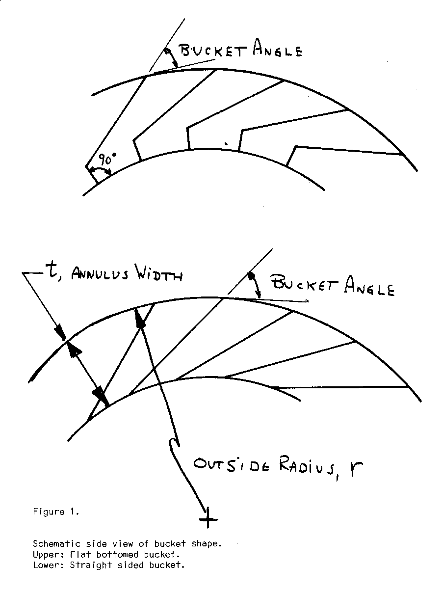
were used for overshot and breast configurations. The straight sided buckets are less efficient but simpler to construct. The width of the bottom of the bucket was typically 1/4 of the width of the annulus where that configuration was chosen. Purely radial buckets were used in undershot wheels.
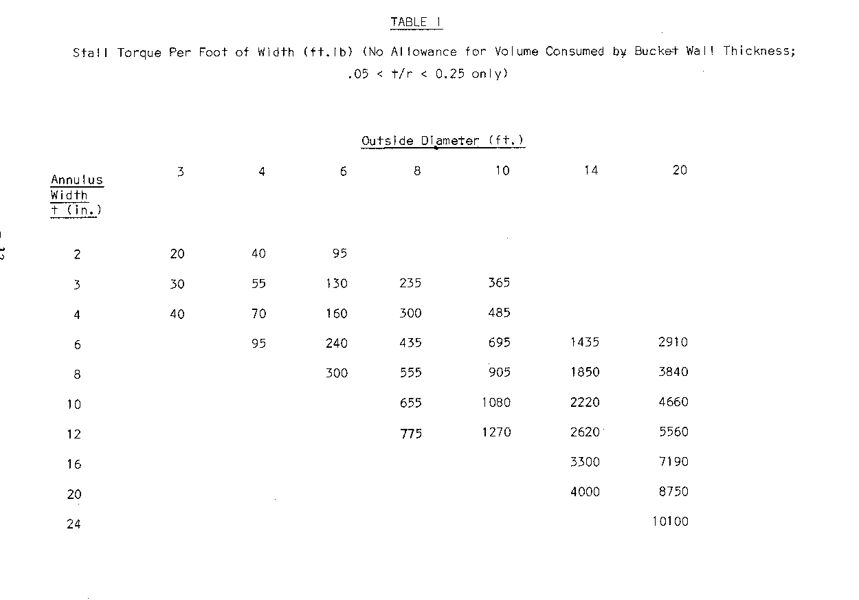
It is convenient to use three of the wheel's dimensions for calculation of the torque capacity of the wheel: the outside radius, r; the wheel width, w, i.e., from side to side; and the annulus width, t, defined as t = (outside diameter - inside diameter)/2. See Fig. 1.
The ratio of the annulus width, t, to the outside radius, r, is important to wheel design as there are practical limits to the useful values which may be employed. In this paper only ratios 0.05 t/r < 0.25 are considered. For smaller ratios, the potential output per foot of diameter of the wheel is considered too low to be practical. For larger values, the buckets become so deep that there is insufficient time to fill each one as it passes under the race exit. Also, since the torque and power depend upon having the weight of water at the greatest possible distance from the wheel axis, increasing annulus depths increases total wheel weight faster than it increases power output. The result is that if more power is needed it is better to increase the O.D. than to increase the annulus width to values exceeding t/r = 0.25. In this way the wheel weight and the structural components to support that weight remain economically most advantageous for a given power output. Historically, wheels have tended to have t/r values around 0.1 to 0.15.
Upper limits on wheel width have tended toward approximately 1/2 the O.D. because of structural problems with wider wheels.
It can be estimated that the overshot wheels operate with the equivalent of approximately 1/4 of the buckets full. That is, the total weight of water doing useful work on the wheel is 1/4 of the total that would be contained in an annular solid of dimensions the same as the O.D., I.D. and width of the wheel. The actual weight distribution of the water is as shown schematically in Fig. 2a because of spillage from the buckets as they approach
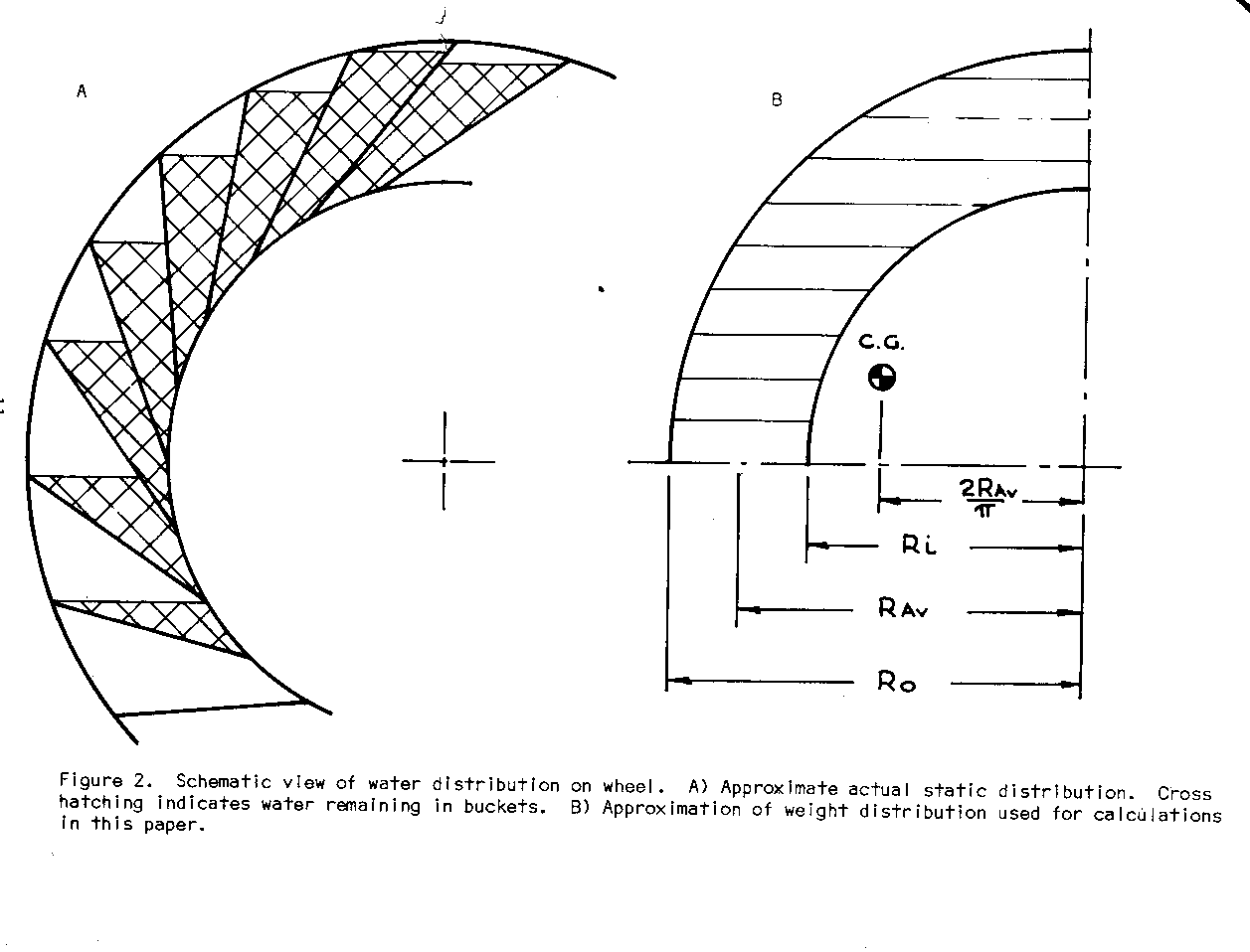
the tail race. If we assume the water is concentrated in the annular quadrant shown in Fig. 2b, the stall torque can be estimated more easily. A suitable correction factor could be applied to account for actual bucket design, if that refinement were considered necessary.
Results for wheels of various dimensions are given in Table 1.
Experience has shown that many non-technically trained users of this information will be more confident of their ability to use data given in tabular than in graphical form. Both will be presented here when appropriate.
B. Power Output
Power output is the product of the torque on the output shaft and the rotational speed of the shaft. On the assumption that there is sufficient inlet water flow to keep the buckets full, thereby keeping the torque constant, the power output increases linearly with speed. In a location where there is virtually an unlimited inlet water supply, this calculation will give an upper limit to the power output that can be expected.
The horsepower output per rpm per foot of width is shown in Table II.
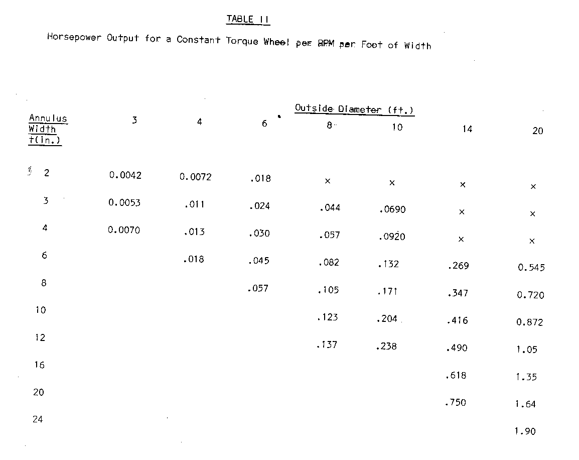
the Table II entry appropriate to the size wheel used times the actual speed in rpm times the Width Of the wheel in feet.
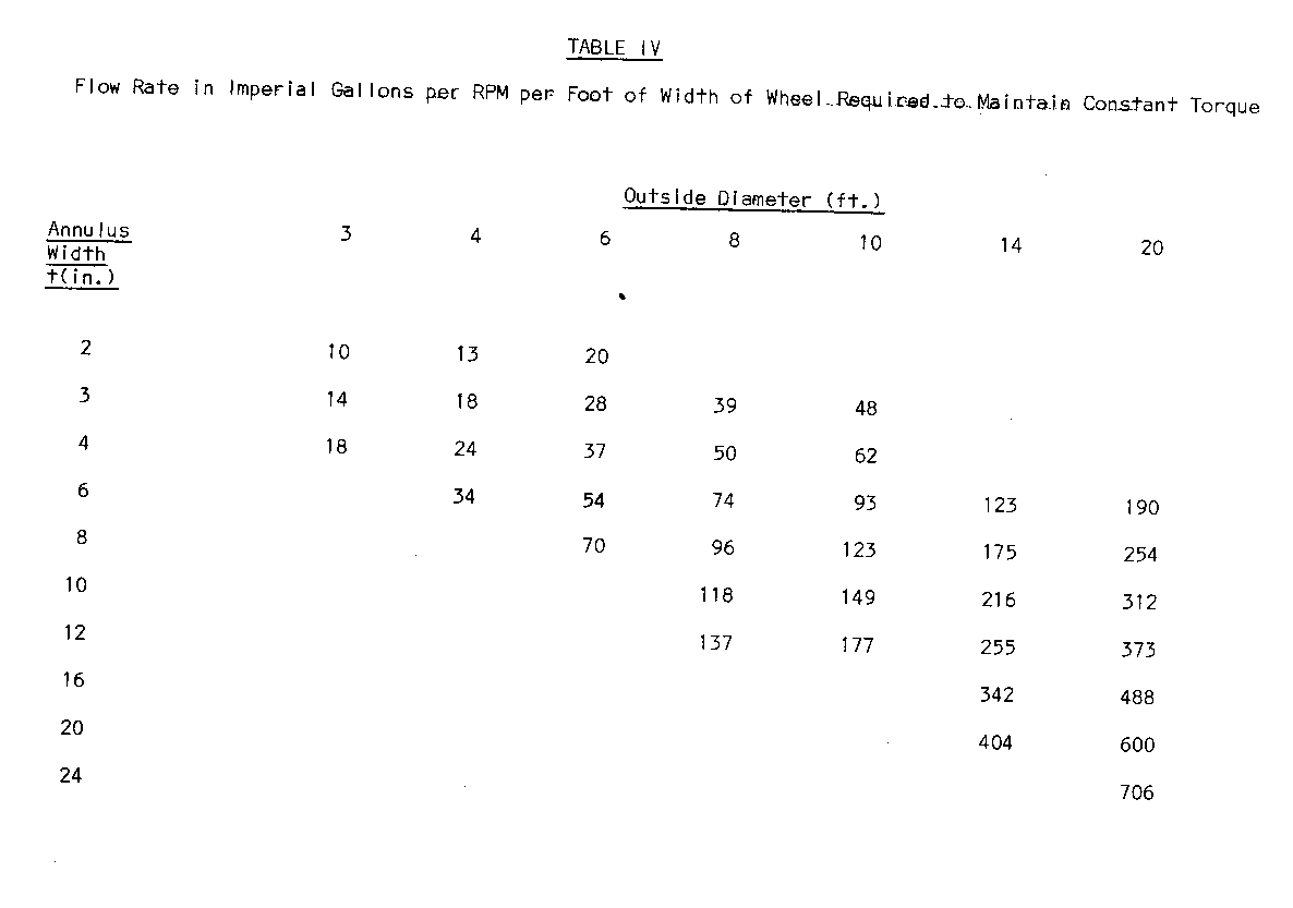
The water power input is the maximum power which the wheel could achieve if it were 100% efficient. It is calculated as the product of the water's specific weight, the volume flow rate, and head and is given in Table III for comparison. This entry is also in horsepower that required to keep the buckets full and is given in Table IV.
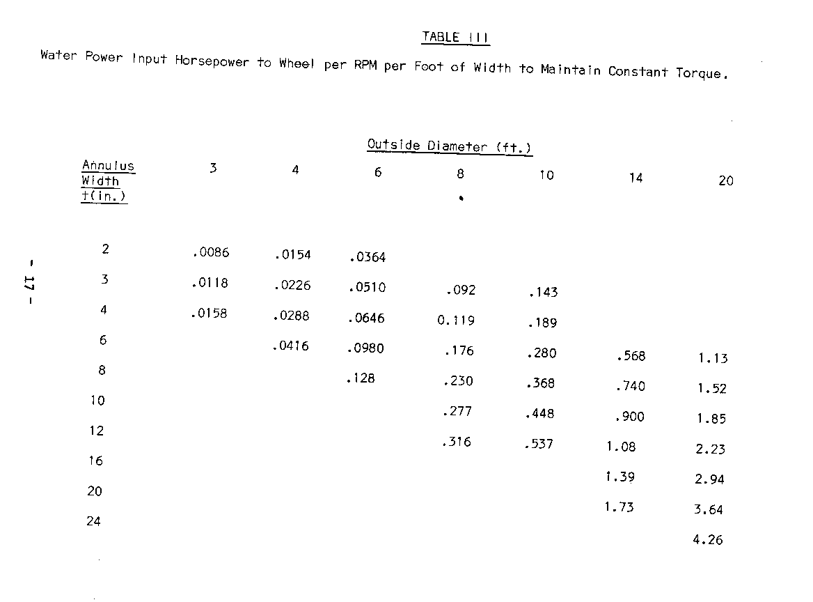
by the bucket wall thickness. This can be corrected for later if desired. The head is assumed here to be the diameter of the wheel. The lower edge of the wheel is the highest elevation permission for tailrace water without interfering with the wheel and is a logical datum. Inlet raceways are seldom found with a significant slope so that velocity effects of raceway water are small. It seems sufficiently accurate to estimate the inlet elevation as the top of the wheel. Any error thereby introduced will be on the conservative side anyway.
Theoretical efficiency values for the wheel using the assumptions adopted so far can be found by taking the ratio of the power output from Table II and the corresponding power input of Table III. These values, for the water weight distribution assumed before, are about 50% for the narrow annulus wheels and drop to just under 45% for the wider annulus wheels. As mentioned previously, a well designed and constructed wheel will give efficiencies better than this. This comparatively modest value is primarily the result of not considering the effect of the water still in the buckets below the horizontal centerline. It reflects the fact that the simplifying assumption that the buckets remain full half way down the wheel and suddenly dump all their water is not accurate. That inaccuracy is tolerable because 1) it makes the analysis so simple and 2) it gives slightly conservative figures for power so that almost every reader will be assured of getting sufficient power even from wheels of relatively amateurish construction.
When the water flow is less than the required to fill each bucket completely as may be the case for a stream of limited size, the power characteristics are altered in that the torque now is a function of speed. Using the assumption of one annular quadrant working, but not full, the volume of water, V, in the quadrant is
V = Q/4N where Q = volume flow rate ([ft.sup.3]/min)
N = speed (rpm)
The weight of water in the annular quadrant at any speed is then pgV where
p = density of water
g = gravitational acceleration
With units in feet, pounds, and minutes, the horsepower to be expected from this annulus working is
hp = 2[pi] NT - 33,000
where T = pgV[bar]x = pgQ[bar]x - 4N
[bar]x is the distance to the centroid of the annular quadrant from the rotation axis. It is equal to average diameter. [D.sub.av], of the annulus divided by [pi].
Therefore
hp = 2[pi]NpgQ[D.sub.av] = pgQ[D.sub.av] - 4[pi]Nx33,000 66,000
The power is independent of the speed. The efficiency is the same as calculated previously. It is because the output power is a function of the average diameter, that the efficiency drops off for wide annulus wheels of a fixed outside diameter. Potential power output from a wheel operating under the conditions of constant flow may be estimated most easily by the equation for water input power, assuming 50% maximum efficiency and head equal to the outside diameter.
Power under constant flow conditions for various diameter wheels is shown in Table V for likely attainable flow rates. The values
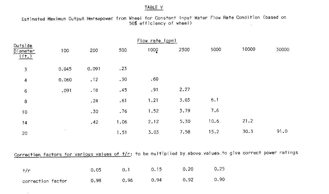
entries by factors as shown at the bottom of the table for various practical t/r values. The author's prototype with t/r = .17 tested at approximately 150 gpm, gave output power of approximately .06 hp in reasonable agreement with the values predicted in Table V.
Blank spaces are left where flow rates are impractical for the wheel size given. Upper bounds to practical flow rates for various wheel sizes are found by multiplying the entry from Table 1 by the practical upper limit of speed and width for the O.D. and are shown in Table VI. Lower bounds are subject to considerably more guesswork. On the assumption that it would be uneconomical to construct a wheel of width less than 1 ft. and to operate it at less than 25% capacity (completely arbitrary choice) for the speeds quoted in Table VI the useful lower bounds may be estimated. These are indicated by blank under the 100 gpm and 200 gpm columns in Table V.
TABLE VI
Upper Limits on Useable Flow Rates for Various Size Wheels in Imperial Gallons Per Minute (assuming wheel width = 1/2 (O.D.) and peripheral velocity is 5 ft/sec.)
Outside Diameter (ft.)
3 4 6 8 10 14 20 Annulus Width RPM at 5 ft/sec peripheral velocity +(in.) 32 24 16 12 10 7 5
2 500 625 1000 3 700 900 1400 1900 2500 4 900 1150 1800 2400 8000 6 1650 2600 3500 4500 6000 9500 8 3400 4500 6000 8500 12000 10 5500 7500 10500 15500 12 6500 9000 12500 18500 16 17000 24000 20 20000 30000 24 35000
The upper limit to the speed at which the wheel will operate depends primarily upon the rate at which the wheel slings the incoming water off so that it is not utilized. This depends primarily upon the speed and radius of the wheel and secondarily upon the bucket configuration and its relation to the inlet water.
The figures quoted in Table VI are based on the rule of thumb peripheral velocity of 5 ft/sec. With smaller wheels this is a bit high, based on prototype tests. With the larger wheels the peripheral velocity may be as high as 8 ft/sec.
In summary, the type of power vs. speed curve that one can expect from a water wheel is as follows for fixed flow rates: Linearly increasing from zero speed up to the speed at which the buckets can no longer be completely filled by the prevailing flow, then constant up to the speed at which significant amounts of water are rejected from the wheel by slinging action, thereafter decreasing in proportion (roughly) to the square of the speed.
C. Bucket Design
The optimum bucket design is taken to be that which produces the greatest torque on the wheel shaft. The upper limit to this condition is that the buckets fill completely at the top, carry the full water weight with no spillage to the bottom and dump their loads there. There is not a practical method of achieving this maximum. With fixed buckets, the best we can do is minimize spillage from the buckets as they travel from the top, where they are filled, to the bottom where they should be empty (so as to limit losses incurred by carrying water up the back side of the wheel).
There are broadly two styles of bucket as shown in Fig. 1. In the
straight sided bucket the limits on the angle the bucket makes with the tangent at the O.D. or I.D. (See Fig. 1) are from tangential (0[degrees]) to radial (90[degrees]). With tangential buckets, the filling process is slow at the top because of the very shallow angle with respect to the incoming(nearly horizontal) water. Furthermore the emptying process at the bottom is not complete until after the bucket passes bottom dead centre. This carries some water up the back side and consequently reduces the efficiency. At the other extreme, radial buckets are nearly empty by the time they have gone 1/4 turn from the top because the bucket wall is then horizontal.
We can estimate the optimum angle by assuming that the greatest effect will be due to the bucket whose weight is acting at the greatest distance from the shaft. By drawing buckets of various angles we can estimate, graphically, the optimum. While the tangential bucket carries the greatest amount of water, its centroid distance is not a maximum The maximum occurs at a bucket angle (to the tangent at the I.D.) of about 20[degrees]. While the amount of water still retained at 90[degrees] after top dead centre by this bucket shape is about 20% less than for the tangential bucket, the loss is compensated for in the early filling and early emptying. Especially on emptying, the 20[degrees] inclination is a major factor since the length of the bucket (distance from I.D. edge to O.D. edge) is more than 30% shorter than the tangential bucket. With a 30[degrees]-bucket, the weight carrying capacity at 90[degrees] after top dead centre is down to about 65% of the tangential, a figure which is so low that it cannot be compensated for by the secondary effects on efficiency such as filling and emptying. This graphical technique, while of no additional value in designing any individual wheel, also shows that the assumption of the distribution of water over an upper quadrant is a reasonable one for estimating torque.
I recommend the bucket wall angle be kept between 200 and 250 to the I.D. tangent.
The use of flat bottomed buckets does not significantly change the water carrying capacity for wall angles of 20[degrees]. The purpose is to decrease the distance the water must travel to empty the bucket. Its use is increasingly beneficial at large t/r ratios but the builder must accept that the construction is somewhat more complicated than that of the straight sided bucket. Bottom widths should be approximately 1/4 of the annulus width, t. This will cut 25% off the side width with the attendant saving in travelling distance to empty the bucket. The significance of this is that less water is carried up the back side of the wheel. Any water carried up the back side lowers the efficiency. I cannot give figures for the improvement of efficiency using flat bottomed buckets but it seems hard to imagine as much as ten percentage points.
Historically, bucket shapes have varied considerably. They were, as far as I can determine, chosen emperically. (In a historical sense this is a euphemism for "arbitrarily" or "by educated guesswork"). By the time engineers, rather than carpenter-craftsmen, were considering the problem the water wheel's usefulness was already on the decline). Even in relatively recent manuals for construction, circa 1850, while wheels were still in general use in the U.S., bucket side angles of 45[degrees] were recommended - a choice which can easily be shown to be less efficient than smaller angles. The 20[degrees] - 25[degrees] figure is, however, in close agreement with the design of two wheels that I know are still in use in the U.S.
The number of buckets to use depends upon the volume consumed by the bucket wall material. The ideal wheel has closely spaced buckets of very thin wall thickness. A reasonable figure to design by is that not over 10% of annular volume should be consumed in bucket material. Typical values for the size wheels discussed here would be 25 - 30 - 1/4 in. thick buckets on a 3 foot wheel and 50 - 1-1/4 in. thick buckets on a 14 foot wheel.
D. Bearing Design
The wheel itself has only one rubbing or sliding part subject to wear, viz. the bearings upon which the axle is supported. Standard bearing design is covered in almost any machine design text. In the manufacture of such a device as is discussed here, the value of such standard" bearings is questionable. Fully weather-proofed ball or roller bearings are too expensive and complicated to satisfy the initial criteria.
Bronze bushings with suitable shaft material would be satisfactory but lubrication and replacement both present problems. The use of wooden bearings is, I think, the best alternative for several reasons:
1. Simplicity of manufacture with local skills.
2. Availability of replacement parts.
3. Negligible cost.
Wooden bearings are used commercially for such applications as washing machine wringer bearings under conditions simulating those proposed for the wheel. Rock maple, lignum vitae, and various species of oak are used commercially, but when these are not native to the country of intended use, substitutes may be found. Among woods with fairly widespread distribution, others which may reasonably be expected to be satisfactory are beech and red mangrove. Forestry departments, when they exist in a country are generally in a position to make useful suggestions.
In the absence of any specific knowledge, the general rule is "the harder, the better".
An estimate of allowable loading based on experience with commercially available wooden bearings would be around 75 psi (for oak) to 150 psi (for lignum vitae) for orientations with the sliding surface parallel to the grain and about 150 to 300 psi respectively for end grain use. If the wood used has strength and density properties comparable to those mentioned above, it is likely that safe loading would be about 100 psi parallel to the grain and 200-250 in end grain usage. It remains to be seen what the wear resistance at these pressures will be, but structurally the figures given can be used with confidence.
Length to diameter ratios of bearings in this application would reasonably be expected to be about unity and on that basis the sizes of the bearings can be estimated for wheels operating at maximum output. An allowance for the weight of the wheel itself is made on the basis that the volume of wood required is approximately equal to the volume of water carried at stall and that the specific gravity of wood operating constantly in water is about unity.
Table VII shows the approximate weight on each bearing per foot of width of wheel. Total weight carried on each bearing is then the product of the Table entry and the width of the wheel in feet. This of course assumes that the wheel is simply supported at each end of the shaft and does not allow for additional loads imposed by the attached machinery. It is important that significant loads due to the Table VII values for the purposes of determining bearing size from Table VIII for the side of the wheel where the machinery is attached. In this event the bearings will apparently need to be of different sizes. In practice, unless the indicated sizes are very different, we usually make both the size indicated by the larger load. Thus one is really longer than it needs to be.
Bearing diameters required to support the various loads are given in Table VIII calculated on the basis of 100 psi in parallel useage and 200 psi for end grain useage and L/D = 1. Values are given to 20,000 lb. to allow for the largest reasonable bearing loads. TABLE VII
Approximate Weight Carried by Each Bearing Excluding Loads Due To Attached Machinery (per foot of width of the wheel) (lb.)
Outside Diameter (ft.)
3 4 6 8 10 14 20 +(in.) 2 24 32 50 3 35 47 70 95 120 4 44 60 89 125 160 6 86 140 185 235 335 470 8 180 240 305 440 675 10 290 370 530 765 12 330 445 635 920 16 820 1215 20 1020 1500 24 1760 TABLE VIII
Minimum Bearing Diameter Required for Various Loadings (in.)
Load (lb.) 100 200 500 ]000 2000 5000 10000 20000 Parallel Useage 1 1-1/2 2-1/4 3-1/4 4-1/2 7 10 14 End Grain Useage 1/2 1 1-3/4 2-1/4 3-1/4 5 7 10
These bearings are assumed to be steel on wood. In the likely event that, especially in larger sizes, the bearing is considerably larger than the required shaft size, a "built up and banded" bearing may be used. A wooden cylinder is built onto the shaft at the bearing location such that the cylinder O.D. is the necessary size. Then steel bands are bent and fastened to the cylinder. The criterion for design in this case is that the product of the diameter and the total width (sum of the individual widths) of the bands equals or exceeds the square of the entry in Table VIII for the corresponding load and grain orientations.
If it is possible to arrange for and be certain of, suitable maintenance, a steel shaft in bronze bushings mounted in commercial plummer blocks (available from hardward suppliers) is probably the best choice. Proper alignment may be a minor problem but is usually fairly easy to overcome. This choice involves additional initial expense and is justified only if maintenance can be guaranteed regularly and frequently.
E. Shafts
Shafting may be wooden or steel. The diameter is of course dependent upon which material is used and the dimensions of the wheel. Minimum permissible shaft diameters d, may be estimated from the equation for stress for solid metal shafting [d.sup.3] = 16 [square root][M.sup.2] + [T.sup.2] - [pi]S
In this equation M is the maximum bending moment occuring where the wheel sidewall attaches to the shaft. It can be estimated as the product of the bearing load (entry in Table VII for the appropriate wheel) and the distance from the wheel side wall to the centre of the bearing. In the interest of keeping the shaft as small as possible, it is therefore desirable to locate the bearings as close to the side of the wheel as possible. (Note that in most cases, it is not critical to include the additional machine load on the bearing, discussed in connection with the use of Table VIII. It must be included only when the external machine load times the distance along the shaft from the point of application of the load is larger than the bearing load from Table VII times the distance along the shaft from the bearing to the point where the wheel is attached.)
T is the torque acting on the shaft and a conservative estimate is found from Table I. S is the allowable shear stress of the metal.
(13,000 is used in the example in Appendix 1.)
For solid wooden shafts two equations are used and the larger diameter of the two results is chosen as the diameter of the shaft.
[d.sup.3] = 16T ---- [pi]S
[d.sup.3] = 32M ---- [pi]B
where S, T and M have the same meaning as before. However, the value of S is typically 150 to 300 psi for hardwoods. B is the allowable bending stress and has a value of about 1500 psi for typical hardwoods. If wood is used it must be sound and free from longitudinal cracks.
For hollow shafting like a pipe, the equation to determine the outside diameter is: [d.sup.3] = 16[square root][M.sup.2] + [T.sup.2] [pi]S(1 - [k.sup.4]) where K = Ratio of inside to outside diameter.
The values of O.D. and I.D. are standardized for pipes. For bearing loads tabulated in Table VIII, on the assumption that the centre of the bearing is 1 foot from the edge of the wheel, the standard pipe sizes shown in Table IX should be satisfactory. Table IX automatically allows for torque that would be reasonable to expect from a wheel of such a size that the bearing load would be given in Table VIII. The values are approximate only since exact values cannot be given until all the details concerning the loads due to the attached pump or machine are known. The values given should serve as a guide only and the final decision should be checked against the equation to be sure. When making substitutions, in assembly, of one pipe size for another, it is permissable to use larger pipe than shown in Table IX but not smaller pipe.
TABLE IX
Minimum Standard Pipe Sizes for Use as Axles with Bearings at 12 inches from Wheel Edge Bearing load (lb) 100 200 500 1000 2000 5000 10000 Pipe Diameter (in) 1" 1 1/2" 2 1/2" 3" 4" 6" 8"
Comparing these figures with the required bearing diameters of Table VIII, it is obvious that when using pipe or solid steel shaft, the bearing will need to be of the build up type when using wooden bearings. An alternative is to use a shaft whose size is selected according to the needs of the bearing size. It will be much stronger (and heavier) than necessary but may save some work. With wooden shafts, the required shaft diameter will usually exceed the required bearing diameter and then one has the choice of reducing the shaft diameter at the bearing location (but only there) or of using larger bearings. In either case the shaft must be banded with steel, sleeved with a piece of pipe or given some similar protection against wear in the bearing.
F. Minor Considerations
We have considered all the major theoretical aspects of selection of sizes etc. to meet specific requirements. All have been based on an assumed efficiency of 50% - a figure which is readily achievable in practice with an overshot wheel. There is one minor consideration over which the design/builder has control which may affect the effiency slightly. The raceway exit should put water onto the wheel slightly before top dead centre. The exact location is a function of 1. flow rate and raceway inclination which affect the inlet water velocity; and 2. the bucket sidewall angle and peripheral velocity which affects how smoothly the inlet water comes onto the wheel. Exact calculations hardly seem justifiable for a machine which by its very nature is as crude and (relatively) inefficient as this. Let it be sufficient that the designer-builder get the water in approximately tangent to, and at the top edge of, the wheel.
V. PRACTICAL CONSIDERATIONS
A. Materials
Most wheels are wood, of course, though they need not be. Among the considerations for selection of the proper material are the ease of working, cost, availability and durability. The average carpenter can make a proper choice on all these except perhaps the latter. Forestry departments in many countries can provide this information on potentially useful species. Others which would probably be suitable are mentioned in the section on bearing design.
Builders of water wheels may naturally consider a "marine" plywood as a likely material. It is convenient to work with but the quality varies widely around the world. Because even the best grades have a doubtful durability when operating continuously in water unless painted, plywood should be chosen only when it can be well cared for or when a relatively short life is anticipated Regarding the framework to mount the wheel on, bamboo might seem a logical choice in many countries but the durability is such that it probably would require more long term care and replacement than other materials. The species listed for the bearings in section IV D are all fairly durable under constantly wet conditions and should be the first to be considered.
B. Construction Techniques
Any person sufficiently skilled to build a water wheel will probably also be sufficiently knowledgeable to work out most of the construction details. This manual is intended to give the engineering groundwork necessary to select the proper overall size of wheel to meet a given need and to make sure that prevailing water supplies are, in fact, adequate. However, a few general suggestions may help the reader avoid some pitfalls.
Attachment of the wheel sides to the shaft, whether the sides are spoken or solid, can be accomplished in many ways. If a steel shaft is used, a thin flange plate can be welded to the shaft (if such facilities are available) and this greatly facilitates the attachment. With a solid side plate there is no further problem but if the spokes are used, the bending in the spokes at the flange must not be so great as to break the spokes. The spokes should be attached to the flange with two or more bolts and the distance required between the bolt holes to support bending varies with wheel diameter and the rigidity of the spoke/wheel joint. For a flexible joint the required a distance would be approximately 1/10 to 1/12 of the outside diameter of the wheel. For example, on a 12 foot wheel, when using radial spokes attached to a flange by 2 bolts and to the wheel side plate (annular ring) by one, the flange bolts should be about a foot apart on each spoke.
Alternatively if the spokes are quite rigid and firmly attached to annular ring of the wheel as with 2 or more bolts, the bolt hole separation can be reduced to 1/20 of the diameter of the wheel at the flange.
A simple spoke arrangement to use is pairs of spokes, (one spoke of each pair on each side of the shaft) crossing at right angles to make a shape like the tic-tac-toe or noughts and crosses symbol. The wheel axis runs through the centre square and the extremities of the lines are attached to the wheel annulus.
Any glue used should be highest quality waterproof glue for obvious reasons. Resorcinol glue is probably the best choice.
Bucket attachment to the side wall may be made by either grooving the side wall to receive the bucket edge or by attaching strips to the inside of the side wall to fasten the buckets to. There is an advantage to the annulus shape of side wall in that the inside of the bucket is accessible from the I.D. This makes closing off the inside of the bucket simpler because the necessary pieces can be inserted through the I.D. With solid sidewalls, the buckets must be made complete and non-leaking before the sidewall is attached. This is by no means impossible but may be more difficult.
If a solid sidewall is used, holes should be drilled adjacent to the bucket bottom into the space between the bucket and the haft to let any leakage water out. A solid side wall would not commonly be used. Spokes offer several advantages.
Numerous books are available to give helpful hints on various construction techniques for the truly amateur builder.
C. Maintenance
The wood used may be painted or varnished for a protective coating. This will obviously extend the life of the wheel. Periodic repainting, if desired, can be carried out. The decision on painting must be made on purely economic grounds. If a very durable wood has been used initially, painting is a luxury. If a somewhat less durable species is used, painting is probably cheaper and easier than early replacement or repair of the wheel.
The only major maintenance problem is in bearings. Generous allowances have been made in the figures in Table VIII but the bearing will still ear. This will drop the wheel from its original position. Shimming under the bearing block will compensate for this. Bearing replacement, when the block is completely worn through is a simple matter.
Lubrication is totally unnecessary with lignum vitae or commercially processed maple, if available. With the other species, we can not make such a flat statement. Generally speaking the bearing should be made from the hardest wood available and lubricated as needed. Oils and grease in small amounts will probably do no harm and may slow the wear rate. Pig grease and tallow would certainly be harmless and might help.
PART TWO: APPLICATIONS
I. WATER PUMPING
A. Pump Selection
The only type of pump which is reasonable to use at the slow speed of the wheel is a positive displacement pump. They are called by various names such as bucket pump, lift pump, piston pump, windmill pump and occasionally even simply by brand name such as "Rocket" pump. Numerous models are available commercially and vary in cost from a few dollars for small capacity pumps to several hundred for high capacity, high head, durable, well manufactured units. Units can be manufactured at low cost in the simplest of workshops. Details are given in Appendix II.
Such pumps may vary in bore size, stroke length and head capacity. There is a practical limit to the speed at which they can operate. This is usually above the frequency of the fastest of wheels. A frequency of speed multiplier such as a multi-lobed cam or a gear set may be used, but these more complicated pumps and mechanisms, while increasing the efficiency of the pumping process, contravene the criteria of Section II, Part One for simplicity and will not be discussed. We will discuss only very simple pumps.
Even with simple single or double acting pumps there are certain problems. one single acting pump attached to the wheel will cause speed surges on the wheel because of the fact that actual pumping takes place only half the time. The other half is spent filling the cylinder. During this filling stage considerably less wheel torque is required than when actually pumping. The speed surge can be partially overcome by using
- two single acting pumps 180[degrees] out of phase so that one of the pumps is always doing useful work;
- a double acting pump which has the same effect as 1. but is built in one unit; or
- best of all two double acting pumps 90[degrees] out of phase.
Such use of multiple simple pumps will also improve the overall efficiency of the system. (In general one unit can be attached easily to a crank at each end of the wheel shaft).
There are pressure variations in the delivery line which depend on several factors. As long as the peak pressures do not exceed the capacity of the pump and related mechanism, nor stall the wheel, such variations will cause no harm. The pressure peaks can be damped with an air chamber in the delivery line or smoothed by using two or more simple pumps as mentioned in the preceeding paragraph. The possibilities are so numerous and the details sufficiently complex that they cannot all be included here. A pump expert or pump design manual should be consulted if the design ideas given here seem insufficient for the user's needs.
In general the pressure peak will be a function of the peak piston velocity, the pump bore size, the delivery pipe size, the length of the delivery pipe and the type of pipe used. When speaking of pump performance and design requirements, the term "head" is encountered often. It is a means for visualizing the fluid pressures involved in the pump or attached pipes. It means the height of water in a vertical pipe necessary to produce, at the bottom of the pipe, the pressure being referred to. The pressure is an actual system will not, in general, be produced just by a static column of water but it will be the same as if it were. It's just a handy shortcut often used by fluids engineers. The head The head required at the pump outlet will be made up of two main components:
- the actual change in elevation to the delivery pipe exit, i.e. the (vertical) height of the hill; and
- friction loss in the pipe which is given by the equation: L V friction loss = f - - D 2g where f = friction factor obtainable from handbooks or Table X
L = length of pipe
D = inside diameter of pipe
V = velocity of water in the pipe g = gravitational acceleration
(Note: Units for dimensions must be consistent. See Appendix I for an example of the use of this equation).
TABLE X
Estimated Friction Factors for Cool Water
Water Velocity (ft/sec.)
1 5 10
Old Iron Pipe .045 .040 .038
New Iron Pipe .030 .023 .021
Plastic Pipe .025 .017 .015
It is evident that this becomes a major factor in very long pipes, in small diameter pipes, or with high velocities. The water velocity in the delivery pipe is a function of the peak pump piston velocity and the ratio of the pump bore size and the delivery pipe size. Peak piston velocity for pumps attached directly to the wheel is given in Table XI for various strokes and wheel speeds.
From Table XI, the delivery line velocities can be estimated simply by multiplying the Table XI entry by the ratio of the pump bore area and the delivery pipe area. That is, piston velocity times piston area = water velocity in delivery pipe times pipe bore area.
As a rule of thumb, this resulting delivery pipe velocity should be a maximum of 10 ft/sec. in short runs, and even smaller for very long pipes. The peak head required of the pump will be the sum of the two different heads mentioned, i.e., elevation change plus friction loss head.
The bore size (piston area) and peak head occurring during pumping will determine the force required at the pump rod since force on an area is the product of the area and the pressure acting on that area. Figures for force at the rod are given in Table XII. No allowance is made for rod diameter so the figures given are conservative. Bore sizes quoted are commercially available.
TABLE XI
Peak Pump Piston Velocity (ft/see) for a Pump Rod Attached Directly to a Crank on the Wheel
Wheel Speed Stroke (in.) (R.P.M.) 2 1/4 4 6 8 10 12 5 0.048 0.087 0.129 0.172 0.216 0.260 6 .059 .104 .156 .208 .259 .310 8 .078 .138 .207 .276 .345 .414 10 .097 .173 .259 .345 .432 .518 12 .117 .208 .312 .416 .520 .624 15 .147 .260 .390 .520 .650 .780 20 .195 .345 .518 .690 .865 1.04
TABLE XII Peak Force on the Pump Rod of a Piston Pump Required for Various Bores and Heads (lb.)
Peak Head (ft.) change in elevation and friction loss
Pump Bore (in.) 50 100 200 300 400 500
1 1/4 30 60 110 370 220 280
1 1/2 40 80 160 240 320 400
1 3/4 60 110 220 320 430 540
2 70 140 270 420 560 700
2 1/2 110 220 440 660 880 1100
3 1/4 185 370 740 1120 1480 1850
4 1/4 315 630 1260 1890 2520 3150
These figures are required to design such parts as clevis pins (if used) and to determine that, if the pump rod is attached directly to the wheel, that the crank arm length times the entry in Table XII does not exceed the torque capacity of the wheel as given by Table I.
Of course, if levers or other torque/force multiplying devices are used, appropriate calculations at the wheel can be made. The force at the pump rod still remains as given in Table XII. The velocity given in Table XI must be adjusted for the change in crank arrangement.
Additionally, if the line is very large so that a large mass of water must be accelerated on each stroke, the inertial forces can become greater than the pressure forces. The inertial forces can be estimated with the aid of Tables XIII and XIV.
TABLE XIII
Volume of fluid in various sized delivery pipes ([ft.sup.3])
Pipe length (ft.)
Nominal pipe size 50 100 200 500 1000
1" .3 .6 1.2 3 6
2" 1.16 2.32 4.65 11.6 23.2
3" 2.46 4.91 9.82 24.6 49.1
4" 4.38 8.78 17.50 43.8 87.5
TABLE XIV
Inertial force (lb.) per inch of stroke for various volumes of fluid at various pump cycles speeds
Pump Cycles per Minute Volume of Fluid in delivery pipe([ft.sup.3])
.5 1 2 5 10 50 100 5 .133 .266 .533 1.33 2.66 13.3 26.6 10 .577 1.14 2.29 5.77 11.4 57.7 114 15 1.20 2.40 4.80 12.0 24.0 120 240 20 2.14 4.27 8.33 21.4 42.7 214 427 25 3.31 6.61 13.2 33.1 66.1 331 661 30 4.78 9.65 19.1 47.8 96.5 478 965
This inertial force is at its peak just as the piston starts its pumping stroke. At this time the friction loss is zero because the delivery pipe velocity is zero. Hence the total rod force at the start of the stroke ill be equal to the force due to the static head plus the inertial force. It should be compared with the rod force when the friction loss is a maximum and the components designed to withstand the larger of the two.
We can calculate the power required to accomplish pumping under various conditions of head, flow rate and pump type. These figures are given in Table XV for steady flow and are adjusted for unsteady flow explained below.
This is the theoretical minimum power input required to the pump under steady conditions.
Under the unsteady conditions of a piston pump, to estimate the water wheel power capacity required, multiply the table entry by 2 1/2 for one single acting pump, by 2 for one double acting pump or two single acting pumps 180[degrees] apart or by 1.5 for 2 double acting pumps 90[degrees] apart. This will give an estimate of the size of wheel and flow rate required to the wheel.
As mentioned near the beginning of this section, there will be speed fluctuations in the wheel which may be pronounced in smaller wheels working near their capacity. This is no particular disadvantage so long as the stall torque capacity of the wheel exceeds the minimum torque necessary to keep the pump moving. The magnitude of the fluctuations decreases with double acting or multiple pumps installations and where the mass of the wheel is such that a flywheel action begins to take place.
TABLE XV
Horsepower Required for Water Pumping at Various Flow Rates and Heads (both assumed steady)
Total Head (ft.) Flow Rate (imp.gal/hr.) 50 100 200 300 400 500 5 0.00125 0.0025 0.0050 0.0070 0.01 0.0125 10 .0025 .0050 .01 .015 .02 .025 25 .00625 .0125 .025 .0375 .05 .0625 50 .0125 .025 .05 .075 .1 .125 100 .25 .50 .1 .15 .2 .250 150 .0375 .0750 .15 .225 .3 .375 200 .05 .1 .2 .3 .4 .500 250 .0625 .125 .25 .375 .5 .625 300 .075 .15 .3 .45 .6 .75 500 .125 .25 .5 .75 1.0 1.25 1000 .25 .5 1.0 1.5 2.0 2.5
"See text for correction factors for various types of pump sets."
The volume pumped per stroke varies slightly with the design of the pump and with the bore and stroke sizes. One commercial manufacturer quotes figures which can be taken as representative. These are given in Table XVI.
B. Method of attachment to wheel
In activating any piston pump, it is done ideally, such that straightline motion of the piston rod is achieved. Any bending in the rod puts undue side loads on the discharge head seal and on the piston bucket. Straightline motion mechanisms are described and discussed in textbooks, so I will not endeavor to give details of the common mechanisms. The books seldom mention however, the practical problems which arise when trying to use such mechanisms. Nor do they usually compare advantages and disadvantages. I will mention some possible mechanisms along with the advantages and potential problems.
A slider and crank mechanism (See Fig. 3) is attractive as a simple
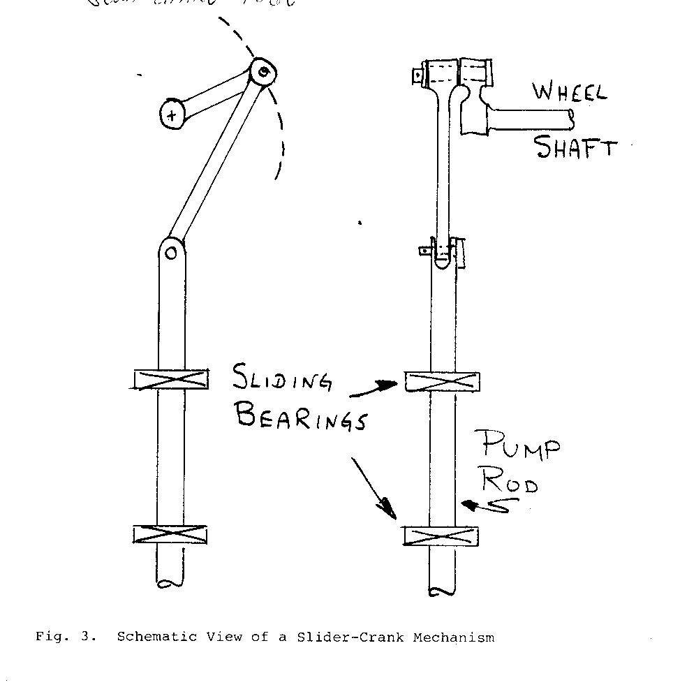
device with the advantage of requiring no special techniques to prevent bending moments on the pump plunger. Stroke is easily adjustable by attaching the crank pin to the wheel shaft via a flange plate with holes drilled at various distances from the rotation axis, through which the crank pin can be fixed. Unless a double acting pump is used, the pumping stroke and return stroke will have different forces on the crank pin resulting in non-uniform wheel rotational speed (unless compensated for by other means - such as attaching single acting pumps operating 180[degrees] out of phase). This non-uniform motion can be alleviated to an extent by attaching the slider (pump axis) offset from the wheel axis. It then becomes a form of quick return mechanism. This, however, increases the side load on the slider during the return stroke, which necessitates moving the slider bearings apart (increasing the slider length) to maintain the same slider bearing pressure as with the symmetrical arrangement if bearing pressure and the resulting frictional drag on the slider become large enough to cause a problem. Lubrication of the slider bearing presents a problem. Although precautions can limit somewhat the exposure to water in the bearing, it is unlikely that the bearing can be completely protected. Pressure grease fittings using a suitably wash-resistant grease might prove suitable. Packing box style lubrication with oily felt or rags could also be successful. Both methods rely on periodic attention, which could be of an intolerable frequency. There are also the crank pin and clevis pin at the slider to be lubricated. Finally, alignment is a potentially tricky problem because of the narrow tolerance allowable on parallelism of the wheel shaft and crank pin and on perpendicularity of the plane of the slider crank mechanism with the wheel shaft. One major advantage compared with the next method discussed is that since the pump body can be fixed if the alignment is sufficiently accurate, the connection with the distribution pipe can be rigid.
TABLE XVI
Quantities of Water Pumped per Stroke for Single Acting Pumps of Various Bore and Stroke Sizes (Imperial Gallons)
Stroke (in.)
Bore (in.) 2 1/4 4 6 8 10 12
1 1/4 .009 .016 .023 .032 .040 .049
1 1/2 .013 .023 .035 .045 .057 .069
2 .023 .040 .062 .082 .102 .122
2 1/2 .035 .064 .095 .127 .159 .191
3 .052 .092 .139 .184 .230 .278
3 1/2 .070 .125 .187 .248 .312 .276
4 .092 .163 .245 .227 .410 .489
5 .143 .255 .382 .510 .638 .765
A second method of attachment is to pivot the pump body about an axis parallel to the wheel shaft (as on trunnions), attach the pump rod end to the same kind of crank pin as before and let the pump oscillate side to side as the piston goes up and down. (See Fig. 4). This eases the difficulty of the alignment problem involving
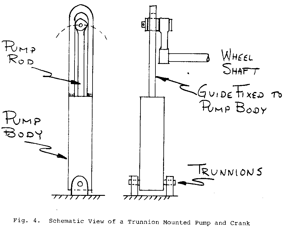
the plane of the crank mechanism previously discussed but introduces new complications. The pump rod is subjected to side loads. This is ordinarily intolerable at both the gland and the bucket but fortunately is easily overcome by a simple frame attached to the pump with sliding bearing surrounding the crank pin which the pump rod end (at the crank pin) then slides in. The bearings absorb all the side loads required to cause the oscillation, leaving the pump rod loaded linearly only. Side loads on these slider bearings would be smaller than the side loads on the slider in the slider crank mounting so that the sliding bearing problems with this technique are somewhat simpler. A serious objection to this mounting method is the necessity for a flexible connection from the pump to the distribution pipe. If the reader intends to build his own pump, which would be likely if considering this particular arrangement, plan to have the outlet of the pump colinear with the trunnion axis. In this way a simple seal to allow the pump exit pipe to oscillate in the delivery pipe will suffice. This method of flexible connection will probably be the most durable.
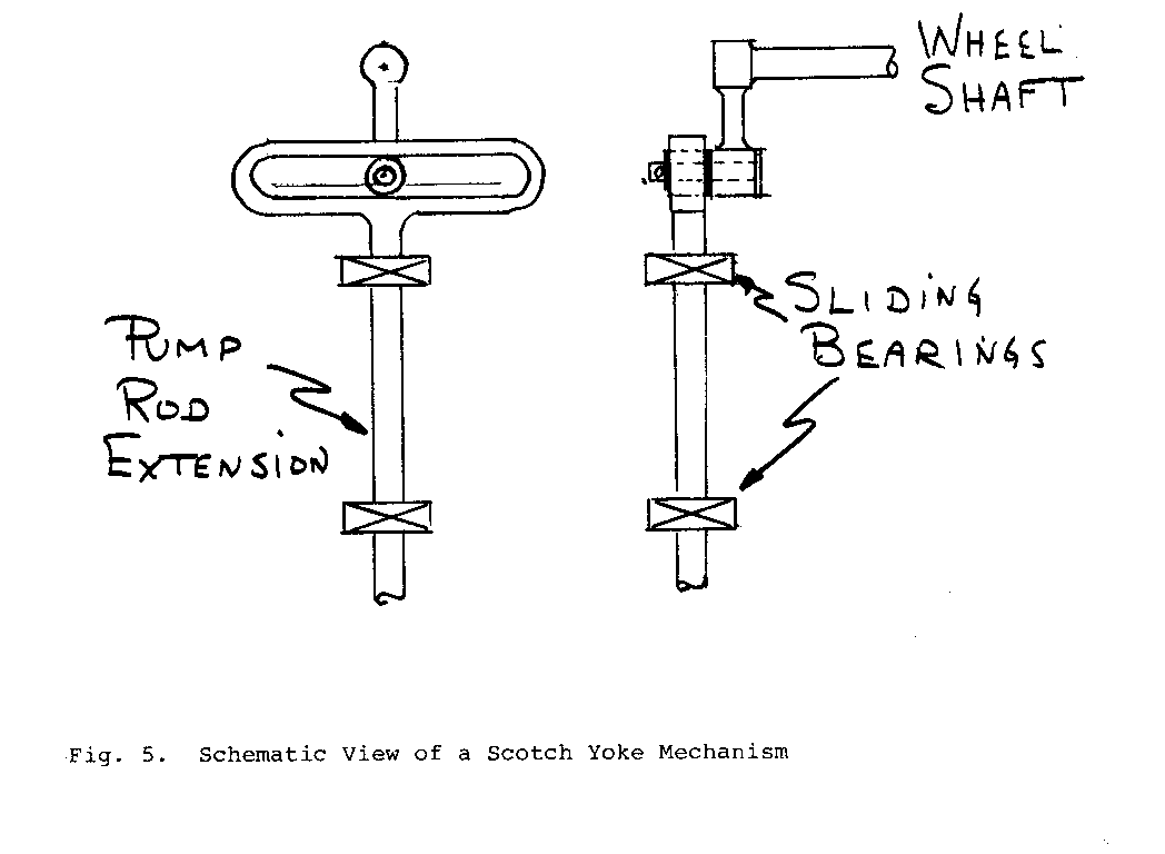
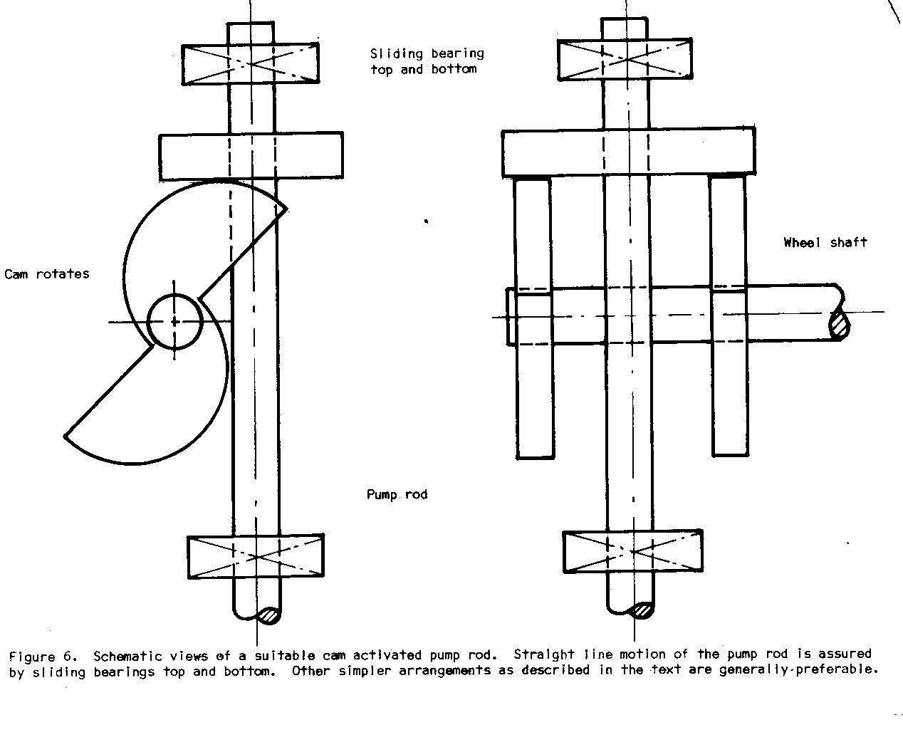
The scotch yoke mechanism (See Fig. 5) is simple and direct but may
require more sophisticated machining than available equipment will allow. Furthermore, there is the potential danger of excessive wear and short life if the lubrication is insufficient. This is not generally a suitable mechanism for unattended use in harsh conditions. A cam activated pump rod is an attractive alternative. It eliminates the need for any linkage, simplifying the alignment problem and eliminating some parts. Side loads on a properly designed profile would be very small and a sliding bearing on the outboard end of the pump rod would easily absorb it. A suitable cam profile is given schemetically in Fig. 6. Force for
the return stroke can easily be supplied by a properly weighted pump rod and the simplest location for such weight would be immediately above the follower plate. Solid mounting of the pump in this case allows rigid supply piping to be attached directly to the pump.
A pump bought ready made with a handle can be attached quite simply by a rod suitably aligned between a crank on the wheel and the free end of the pump handle. Then force and velocity calculations must be modified.
Various straight line motion linkages are easily constructed. They have the advantage of simplicity and durability even under harsh working conditions. Many such linkages are discussed in books on Theory of Machines and Machine Design.
One simple technique to achieve straight line motion seldom seen in texts on machine design is to run a cable over a pulley such that the end of the cable attached to the pump is colinear with the pump rod. The other end can be attached to the wheel crank and the cable provides sufficient flexibility that no solid linkage is needed. An alternative to this approach is to link the wheel crank to a sector of a pulley sheave in such a way that the sheave oscillates as the crank rotates. With the cable wrapped far enough around the sector so that the cable always remains tangent to the sector and fixed there, the free end of the cable can be attached colinear with the pump rod to provide straight line motion. This is the mechanism used on oil drilling rigs.
The cable, as a part of the drive mechanism, can be made very long in order to drive pumps located at a considerable distance from the wheel itself. Such a technique provides the means to power, for instance, a shallow bore pump in the middle of a village using power generated at a stream some distance away.
C. Piping
For any water distribution system where the water must be transported to a higher elevation, piping is usually required. There are alternatives such as buckets on an endless belt, etc., but that is outside the scope of this manual.
The choice will probably fall between polythene and galvanized iron pipe. There are advantages and disadvantages to both. I shall endeavor to give some helpful information to aid the designer in making the best choice.
Polythene pipe is available in long (now around 200 meter) lengths so numbers of couplings and joints are greatly reduced compared to the iron pipe which comes in short lengths (21 1/2 ft typically). It is flexible (softer, weaker and more elastic in strict engineering terminology) and for this reason is more susceptable to damage from bush knives, rocks, pig hooves, etc. Its strength is limited such that it is rated to support at best 300 foot normal working heads at standard conditions. The strength is strongly temperature dependent however, and at 120[degrees] F head capacity is down to 185 ft maximum. It is not fire resistant. Consequently in open country it would probably need to be buried. If the local soil is very rocky, the burying process must be done with great care to keep the pipe from suffering rock (penetration) damage. Sand is usually used as a bed and cover.
Iron pipe can generally simply be laid on the ground with rock piles to support it through low spots. It will support more than 1000 ft heads with plenty of safety margin. For heads to get that high, the system required will be more sophisticated than can be made by the techniques detailed in this manual.
Prices for the two types are competitive in the higher strength grades of polythene but for low pressure systems, polythene may be substantially cheaper.
Polythene has a smoother bore so that friction losses are less than with iron pipe, although this would not likely be a significant factor. It becomes more important in long gravity feed systems.
Weight of a given length is vastly different. 100 ft of high strength 2" polythene weighs 60 lb while 100 ft 2" standard iron pipe weighs 357 lb. Therefore, long distance transport by hand to very remote areas might influence the decision for polythene even in spite of its other shortcomings.
II. OTHER APPLICATIONS
While water pumping is an obvious use for the water wheel, other machinery can be adapted to use the mechanical power output of the wheel. It is not the intention of this section to attempt to enumerate all the possible applications. Rather, I include this section to offset any impression that may have been given by the preceeding section that water pumping is the most important, or perhaps only use to which the wheel may be put.
Generation of electricity is a possibility which will probably spring to the minds of most people reading this manual. There are wheel driven electric generators in operation in Papua New Guinea today but the number of attempts and failures testify to the fact that it is not a simple, cheap task to make a successful rig. The principal difficulties are the speed step-up required for generators and speed regulation. Low voltage D.C. generation using readily available parts (old auto generators or alternators) avoids the speed regulation problem. Simple starter-motor-pinion/ flywheel-ring-gear sets could be adequate for speed step-up at a reasonable cost. Typical ring gear sets have a lower limit of 10 diametral pitch size teeth which gives a power rating of 10 R.P.M. of about 1/2 h.p. It is, therefore, marginal to expect to produce continuous output from a 12 volt automobile generator at, say, 60 amps for long periods of time without gear problems. The small amount of power generated, the need for 12 volt bulbs, resistance losses in long distribution systems and other problems also mitigate against this being a useful bolt-on accessory. Electricity generation is better left to the higher speed devices which are more amenable to speed regulation such as the Banki Turbine of a centrifugal pump being forced to run as a turbine.
Attachment directly to other mechanical machinery can be accomplished by a variety of coupling devices described in various machine design books. Two circumstances are likely to occur: 1. the machine to be driven will be located some distance from the wheel; and 2. the input shaft of the machine will not easily be aligned with the wheel shaft.
Alignment difficulties are overcome simply and cheaply with old automobile drive shafts and their attached universal joints. Note that the use of one universal joint will not give constant speed on both sides. For a constant input speed, the output is alternately faster and slower than the input depending upon the angle between the two shafts. The speed variations are small and will generally not be of any consequence. If the speed variations cannot be tolerated, either a special constant velocity joint (as from the front wheel drive automobile) or two ordinary U joints must be used, each to compensate for the non-uniform motion of the other.
Flexible shafts are commercially available but are of limited torque carrying capacity.
Solid shafts can transmit torque over considerable distance but require bearings for support and may therefore be expensive. Virtually any stationary machine which is currently hand-powered could be run by water wheel power. The means to accomplish the attachment would vary from machine to machine of course, but only in the case of where the wheel and the machine are separated by long distances should there be any significant problem.
APPENDIX I
Sample Calculation for Wheel-Pump Set
The following is an example of the use of this manual to make decisions relating to water wheel for use in water pumping. The decisions made must be consistent with the bounds placed upon the system by the village's needs (how much power is required) and the geography and size of the supply stream (how much power we can expect to get from the wheel). If the power required is greater than the power that can be generated by the wheel, then the system cannot work. This example is taken from calculations made for Ilauru village, approximately 15 miles south of Wau, New Guinea. One of the possible locations for a wheel is in a stream about 350 feet below the level of the village. The hill is quite steep and would require about 750 feet of pipe. There is a place in the stream where the water level drops quite rapidly through a vertical distance of 8 or 10 ft. The stream is about 10 ft. wide, averages 6 or 9 inches depth and flows about between 1 and 2 ft. per second (estimated by measuring the time for a leaf to travel a fixed distance). That description establishes the conditions to determine the maximum wheel size.
The village has about 300 people. Each person now consumes less than 2 gallons of water per day in the village according to a rough estimate. If the water were pumped into the village, experience in other countries shows that the consumption would increase. A minimum of 10 gallons per day per person is sometimes quoted as a minimum viable scheme. Let us calculate for twice that to allow for expansion of population or of consumption.
1. Total water requirement in gallons per hour 20 gal/person-day x 300 people x day/24 hr = 250 gal/hour assuming storage facilities at the village to allow larger draw at peak hours.
2. Power required to meet this pumping rate from Table XV. 250 gal/hour at approx. 400 ft. head (350 actual ft. rise + some losses as yet uncalculated) requires about 1/2 h.p. under steady conditions.
3. Depending on the type of pump arrangement used, the wheel will need to be designed for 2 1/2 times that for a single acting pump, 2 times that for double acting pump or 1 1/2 times that for 2 double acting pump. Assuming the simplest case of 1 single acting pump we need a wheel of 1 1/4 h.p. potential.
4. Can we get that much power from a water wheel under the stated conditions at the stream? The largest diameter possible is limited by the drop in the stream in a useable distance -- about 8 feet. An 8 ft. wheel will operate at about 12 rpm or less (Table VI). The stream has a flow rate of at least
10 ft x 1/2 ft x 1 ft = 5 [ft.sup.3] - sec sec or 5 [ft.sup.3] x 6 1/4 gal x 60 sec = 1800 gal - sec [ft./sup.3] min min
At 1800 gal/min we should be able to produce 2 h.p. at least from an 8 ft. wheel (Table V) or slightly less depending upon the exact t/r values finally chosen.
Therefore we conclude that the job, in theory, is possible. Had the flow rate been, for example, only 500 gallons per minute, the task of pumping 250 gal per hour to the village would probably have been impossible.
5. At an estimated 12 rpm and 4 ft. width (maximum usually used is half the diameter) we can estimate the annulus width necessary (Table II).
1 1/4 h.p. needed = 0.025 h.p. per rpm per ft of width 12 rpm x 4 ft wide In the entry under 8 ft. diameter wheels we see that all annulus widths listed will provide at least that much power. We now know we can make the wheel less than 4 ft. wide if desired and the annulus width can be between 3 in. and 12 in.
It is now completely established that an 8 ft. diameter water wheel in this location will do the job required.
6. If the wheel operates at 12 rpm and the pump is directly coupled so that there is one stroke per rpm with no added leverage (for instance, as with the wire connection suggested in Part Two, Section IB), there will be one stroke per revolution. To accomplish 250 gal/hr we need: 250 gal hr min --- x ------ x ---------- = .35 gal/stroke hr 60 min 12 strokes From Table XVI that means we need 3 1/2 pump with 12" stroke or 4" pump with 9" stroke etc.
7. If we limit the velocity in the pipe to 10 ft/sec then the pipe size with the 3 1/2" pump (chosen because it is cheaper than the 4" pump) is related to the peak piston velocity and the pump size. From Table XI the peak piston velocity at 12" stroke 12 rpm is .624 ft/sec. The delivery pipe cross section area must be approximately .624 x 11 [(3 1/2).sup.2] 1 --------------- x -- = Pipe area = .64 [in.sup.2] 4 10 This would require a nominal 1" diameter pipe.
8. The pipe would need to be galvanized iron to withstand the pressure of heads exceeding 350 ft. If a nominal 1" pipe is used, the actual peak velocity is about 7 ft/sec.
The friction head loss would be (Table X) friction loss = 0.022 x 750 [7.sup.2] ---- x --------- = 150 ft 1/12 2 x 32.2
Thus the total peak head causing forces on the pump rod would be 350 (elevation) + 150 (loss) = 500 ft.
Commercial 31/2 m. pumps are fitted with 2 in. pipe outlet holes and if 2 in. pipe is used the loss is much less because the velocity is less and the diameter is greater. friction loss = 0.028 x 750 [2.sup.2] ---- x --------- = 8 ft 2/12 2 x 32.2 The saving is obviously substantial but the cost of doubling the pipe size may be unattractive.
9. Assuming we use the 1" pipe we find the required pump rod force from Table XII is about 1850 lb. For a 12" stroke a crank length of 6" is required and so the peak torque on the machine is 925 ft/lb.
From Table 1 we see that this is well within the capacity of the wheel if it is 4 ft. wide.
10. To allow for reasonable future expansion of needs without adding unnecessary weight to the wheel I would select a 4" annulus. Having done that, the bearing loads are (Table VII) about 500 lb. each. Assuming the bearings can be located fairly close to the wheel, say 6" away, the solid steel shaft size required is found from: [d.sup.3] = 16[square root][(6 x 500).sup.-2] + [(925 x 12).sup.2] pi d = 1.65 in
Any solid steel shaft larger than this will be satisfactory.
APPENDIX II
An Easily Constructed Piston Pump
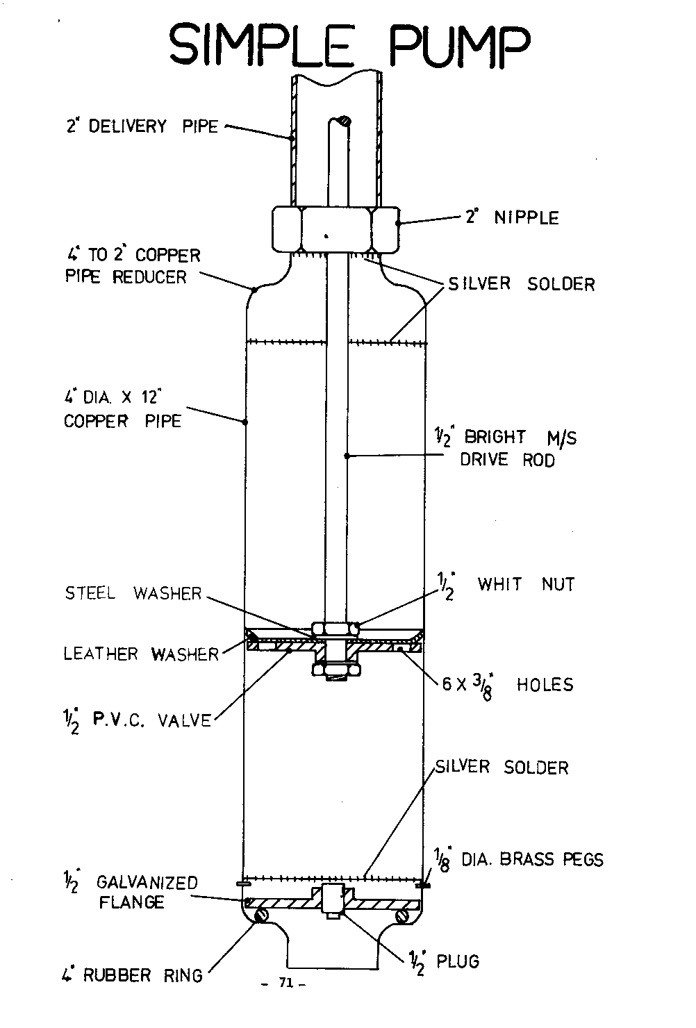
by R. Burton
This pump was designed by P. Brown (of the Mechanical Engineering Workshop at the Papua New Guinea University of Technology) with a view to manufacture in Papua New Guinea. Consequently the pump can be built up using a minimum of workshop equipment. Most parts are standard pipe fittings available at any plumbing suppliers.
To avoid having to bore and hone a pump cylinder, a length of copper pipe is used. Provided care is taken to select an undamaged length and to see that the length is not damaged during construction this system has proved quite satisfactory.
As can be seen from the cross-sectional diagram, the ends of the pump body consist of copper pipe reducers silver soldered onto the pump cylinder. This does make disassembly of the pump difficult, but avoids the use of a lathe.
If a lathe is available, a screwed end could be silver soldered to the upper end of the pump to allow for simple disassembly.
The piston of the pump consists of a 1/2" thick P.V.C. flange with holes drilled through it (see diagram). A leather bucket is attached above the piston and together with the holes serves as a non-return valve. In this type of pump the bucket must be made of fairly soft leather, a commercial leather bucket is not suitable. Bright steel bar is used as the drive rod and has to be thread cut at its ends using a die.
A galvanized nipple is silver soldered to the top copper reducer of the pump to allow the discharge pipe to be attached.
An `O' ring seal of the type used to join P.V.C. pipe is used as a seal for the foot valve. This seal does not require any fixing since it push fits into the lower copper pipe reducer. A 1/2" screwed flange with a plug in its centre forms the plate for the foot valve. This plate must be restrained from rising up the bore of the pump by three brass pegs fitted in through the side wall of the pump above the valve plate. These pegs must be silver soldered in to prevent leakage or movement.
A parts list for a 4" bore x 9" stroke pump is set out below together with a tool list.
Parts
1 only 12" x 4" dia. copper tube 2 only 4" to 1 1/2" copper tube reducers 1 only 1 1/2" galvanized nipple 1 only 1/2" screwed flange 1 only 1/2" plug 1 only 1/2" P.V.C. flange 1 only Rubber `O' ring 4" dia. 1 only piece of 4 1/2" dia. leather 1 only 15" x 1/2" dia. bright steel bar 1/8" dia. brazing rod
Tools
Handi gas kit Silver solder Hand drill 1/2" Whitworth die 1/2" Whitworth tap Hacksaw Hammer
BIBLIOGRAPHY
Village Technology & Water Supplies:
Village Technology Handbook Publ. by VITA, 1815 North Lynn Street, Suite 200, Arlington, Virginia 22209, U.S.A.
Wagner, E.G. and Landix, J.N., Water Supply for Rural Areas and Small Communities, Geneva: World Health Organization (1959)
Handbook of Appropriate Technology Publ. by Brace Research Institute, McGill univ., Montreal, Canada
Handbook of Homemade Power Bantam Books, N.Y. (1974) (Complete Drawings for Water Wheel - Paperback)
Cloudburst Manual Cloudburst Press, Vancouver, B.C., Canada (1973)
Historical;
Banks, J., A Treatise on Mills, 2nd ed. London: Longman, Hurst, Rees, Orme and Brown and for W. Grapel, Liverpool (1815)
Burton, R. (James Renwick, ed.), A Compendium of Mechanics, New York: G. & C. & H. Carvill (1830)
Evans, O., Young Millwright & Miller's Guide. 13th ed., Philadelphia: Lea & Blanchard (1850). Reprinted by Arno Press, c/o Aris & Phillips, Ltd., Teddington House, Church St., Warminster, England
Ewbank, T., Hydraulics and Other Machines for Raising Water, New York: Bangs, Platt & Co. (1851)
Ferguson, J., Lectures on Mechanics, Hydrostatics, Pneumatics, Optics and Astronomy, London: Sherwood & Co. (1825)
Grier, W., The Mechanic's Calculator, Hartford, Conn.: Summer & Goodman (1848)
Hamilton, E.P., The Village Mill in Early New England, Sturbridge, Massachusetts: Old Sturbridge Village Press (1964)
Hughes, W. C., The American Miller and Millwright's Assistant, Philadelphia: Henry Carey Baird (1853)
Lewis, P., The Romance of Water Power London: Sampson Low, Marston & Co. Ltd. (Ca. 1925)
Nicholson, J., The Operative Mechanic and British Machinist Philadelphia: T. Desilver, Jr. (1831)
Usher, A.P., History of Mechanical Inventions Harvard Univ. Press (1954)
Design Details:
Chironis, N.P. ed. Mechanisms, Linkages and Mechanical Controls N.Y., McGraw Hill (1965)
Tuttle, S.B., Mechanisms for Engineering Design N.Y. Wiley (1967)
Black, P.H. & Adams, O.E., Machine Design N.Y. McGraw Hill (1968)
Faires, V.M., Design of Machine Elements London, Collier--Macmillan (1965)
Hoyland, J., Engineering Construction and Materials London, Cassell (1968)
Parr, R.E., Principles of Mechanical Design N.Y., McGraw Hill (1969)
Doughtie, V.L. & Vallance, A., Design of Machine Elements N.Y., McGraw Hill (1969)
Rothbart, H.A. ed., Mechanical Design and Systems Handbook N.Y., McGraw Hill (1964)
Construction:
Bayliss, R., Carpentry and Joinery London, Hutchinson Ltd. (1969)
- Timber Design and Construction Handbook N.Y., McGraw Hill (1956)
Durban, W., Carpentry Chicago, Am. Tech. Soc. (1970)
Keeling, F., Carpentry and Joinery London, Cleaver Hume (1963)
Eastwick-Field, J., The Design and Practice of Joinery London, The Architectural Press (1966)
Andrews, H.J., An Introduction to Timber Engineering Oxford, Pergamon (1967)
Materials:
Miner, D.F. & Seastone, eds., Handbook of Engineering Materials, N.Y., Wiley (1955)
- Properties and Uses of Papua New Guinea Timbers Boroko, PNG, Dept. of Forests (1970)
Berzinsh, G.V., Snegovskii, F.P., Skrupskis, V.P. "Ammonia Plasticized Lignum as New Anti-Friction Material" Vesnik Mashinostroeniya, 1, Jan. 1969, p. 45
O'Conner, J.J. et. al., eds., Standard Handbook of Lubrication Engineering N.Y., McGraw Hill (1968)
Fuller, D., Theory and Practice of Lubrication for Engineers N.Y., Wiley (1956)
Callahan, J.R., "Lignum Vitae Wood for Processing Applications" Chem. & Met. Eng. 51, May 1944, p. 129
Atwater, K. "Lignum Vitae Bearings" Trans. ASME, 54, No. 541, 1932, p. 1
Verney, M., Complete Amateur Boat Building in Wood London, J. Murray (1967)
Pumping:
Southern Cross Machinery Co. Catalogue Industrial Enterprises Ltd., P.O. Box 454, Toowoomba, Qld., Aust. 4350
Sidney Williams and Co. Catalogue P.O. Box 22, Dulwich Hill, NSW, Aust. 2203
- Pumping Manual Morden, Surrey: Trade and Technical Press Ltd. (1968)
Hicks, T.G., Pump Selection and Application N.Y., McGraw Hill (1957)