 Introduction
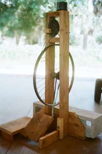
This treadle grindstone can spin a 6” abrasive wheel (of the type used on electric tool grinders) at up to 3000 rpm by means of a single treadle operated by the person using the grinder. Although rotational speed is similar to electric grinders, power is lower therefore short or light grinding passes must be taken. This tool may be a good addition to a shop where electricity is not available.
Operating the Grinder
Ergonomics: Stand on the platform and push the treadle with the right foot. I have found that while standing it is most comfortable to operate a treadle if my treadling foot can extend below my stationary foot, allowing full extension of the leg and toe.
Technique: Get the grindstone up to speed, take a quick pass, give two pumps to the treadle, take another quick pass. A steady hand is easier if the foot is not going at the same time.
Safety: Stand out of line with grindstone to avoid being hit with debris in case the work piece or the grindstone disintegrates. Wear goggles or a face shield.
Prevent tool damage: Cool the work piece in water every few grinding passes to prevent heat buildup and loss of temper (important for any tool with a hardened cutting edge)
Maintenance
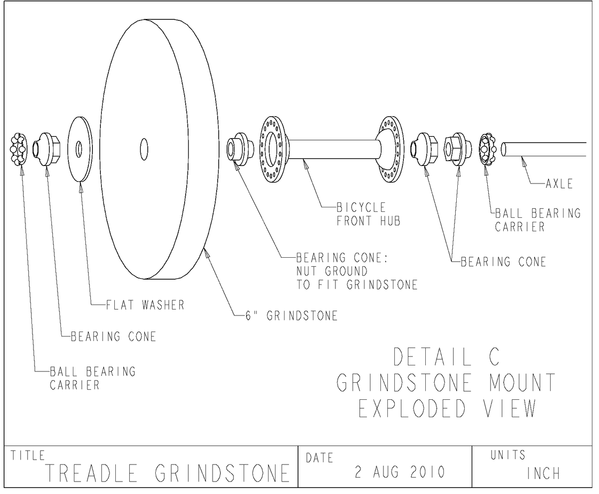
Oil grindstone bearings. Use thin lubricating oil, such as motor oil. Bicycle ball bearings are normally greased, but these run at unusually high speeds and I suspect the grease would give too much drag and cause heat buildup. It is hard to get oil into the bearing cups while the grinder is assembled, but it is possible. Try this experiment: Hold a short piece of wire vertically and dribble a small amount of oil on the top. Watch the oil run down the wire, sticking to it by surface tension. Now, direct the bottom end of your wire into the bearing cup and dribble oil down the wire and into the bearing. Rotate the shaft periodically while doing this until oil begins to run out the bottom of the bearing.
Oil bicycle chain and treadle pivot
Tighten rope. There is no tensioner. When the rope is loose enough that you cannot get the wheel up to speed, shorten the rope by untying it, or cut the rope and retie the ends together, trying to use as little rope as possible. It may feel over-tight initially, but will stretch with time until you need to do this process again. After many such knots are in the rope, cut out the knotty section and replace with new rope.
Dress grindstone: This produces new cutting surfaces. The dressing tool has hardened cutting wheels which chip off small particles of the spinning abrasive wheel.
Disassembly
The bicycle wheel and grindstone are removed by unscrewing the right upright 2x4 frame member and removing the right treadle pivot bolt. Note that the rear shelf (where weights are piled to stabilize the grinder) is not attached to the right frame member.
Drive Rope
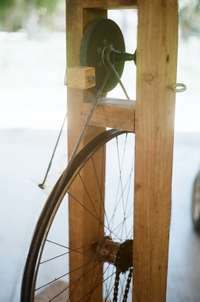
Figure 1. Rope drive detail
The drive rope is ¼” cotton rope, which adequately grips a rubberized surface. The bicycle wheel has a rubber band in the bottom of the rim, cut from a tire of smaller diameter. The grindstone shaft has rubber inner tube wrapped around it (wrap in the direction of rotation). The rope is given a single twist around the grindstone shaft, increasing the area of contact, see Figure 1. The direction of twist will determine which way the rope will “walk” on the shaft. Wrap only one end in rubber and then make the rope walk toward that end.
The drive rope may be assembled without disassembling the frame. Wrap the rope around the bicycle wheel and grindstone shaft to estimate the length. Cut the rope and slip it off of the wheel to give enough slack to tie the ends together. Wrap the rope around the grindstone shaft with one twist, making sure the rope will “walk” to the correct end of the shaft. Tie the ends of the rope with a sheet bend (Figure 2). Slip the rope back onto the wheel and trim the loose ends.
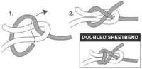
Figure 2. Sheet Bend. A sheet bend is strong but fairly easy to untie. It can also be used to joint two ropes of unequal size; the loop is made in the larger rope and the smaller rope is doubled several times. See www.netknots.com for more useful knots.
Direction of Rotation
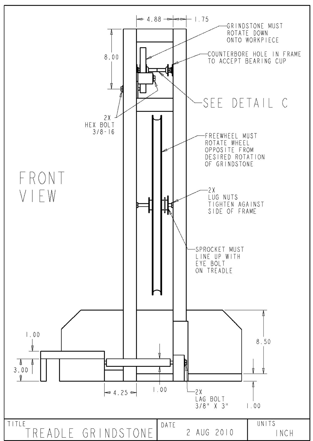
The bicycle wheel and grindstone will turn opposite directions, due to the twist in the drive rope. The grindstone should turn down into the tool rest. With this in mind, make sure the freewheel will turn the bicycle wheel correctly when pulled on by the treadle.
Improving the grindstone
- Make a belt tensioner. The simplest form is an idler wheel that pivots on an arm and locks in place.
- Replace the treadle with a bicycle crank and pedals. This should allow more power since both legs are working. But find a way to keep the operator out of direct line with the grindstone. Also, be careful not to enable the operator to turn the grindstone faster than 3600 rpm; it can fly apart.
- Use a heavy flywheel to store energy so longer grinding passes may be taken without pausing to treadle or pedal. One method mentioned in literature is to cast the bicycle wheel full of concrete. Ideally the most mass would be at the rim, giving greater rotational inertia for the same weight, so another option is to wrap heavy wire around the rim (as you would roll it up on a spool). Allow enough room for the belt to run in the wheel rim.
Grinding wheel speed
This is a rough calculation whose outcome will vary a lot depending on the frequency and travel of the treadle and where the rope rides on the shaft.
Given:
Treadle rate: 2 steps/sec
Bicycle wheel speed: 2 rev/sec
Bicycle wheel diameter: 25”
Grindstone shaft diameter: 1”
Calculate shaft speed: 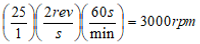
Dimensioned Drawings
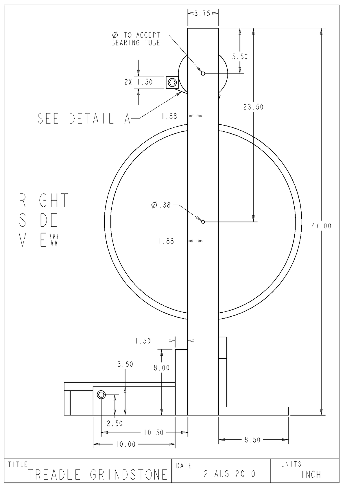
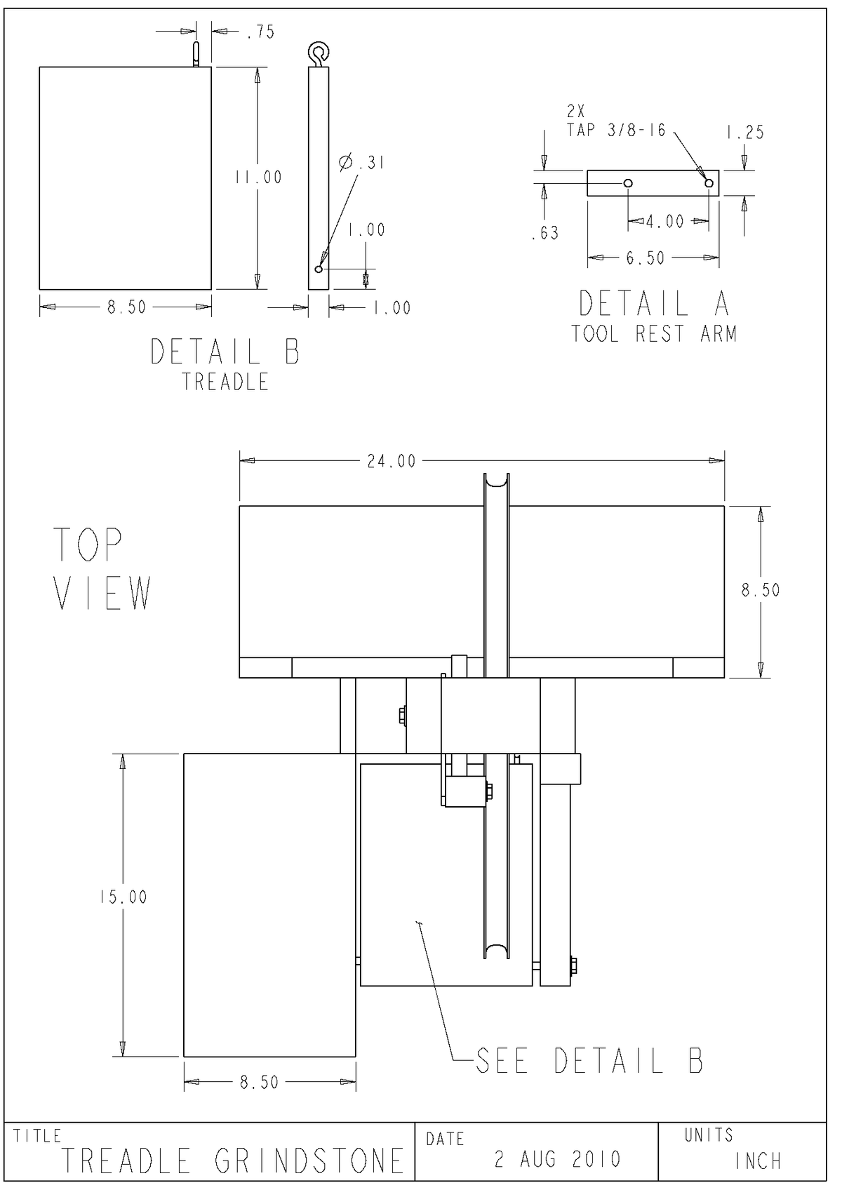
The drawings on the following pages are intended to describe reasonably accurately the grinder built at ECHO. Many dimensions will vary depending on the choice of materials, available dimensions of stock, and the designer’s own free will.
Conversion to metric
1 inch = 25.4 mm