Published VITA 1600 Wilson Boulevard, Suite 500 Arlington, Virginia 22209 USA Tel: 703/276-1800 * Fax: 703/243-1865 Internet: pr-info@vita.org
Understanding Solar Water Heaters ISBN: 0-86619-266-2 [C] 1986, Volunteers in Technical Assistance
PREFACE
This paper is one of a series published by volunteers in Technical Assistance to provide an introduction to specific state-of-the-art technologies of interest to people in developing countries. The papers are intended to be used as guidelines to help people choose technologies that are suitable to their situations. They are not intended to provide construction or implementation details. People are urged to contact VITA or a similar organization for further information and technical assistance if they find that a particular technology seems to meet their needs.
The papers in the series were written, reviewed, and illustrated almost entirely by VITA Volunteer technical experts on a purely voluntary basis. Some 500 Volunteers were involved in the production of the first 100 titles issued, contributing approximately 5,000 hours of their time. VITA staff included Suzanne Brooks handling typesetting and layout, and Margaret Crouch as project manager.
The author of this paper, VITA Volunteer Trinidad Martinez, has extensive experience in the design and construction of greenhouses and solar-wall air heaters, and constructed his own 1,200 square foot adobe home in Tres Ritos, Mexico. Mr. Martinez was also a technical reviewer for "Understanding Adobe." The technical reviewer for this paper, VITA Volunteer James Pringle, is an Associate Editor/Analyst with the Datapro Research Corporation in Delran, New Jersey.
VITA is a private, nonprofit organization that supports people working on technical problems in developing countries. VITA offers information and assistance aimed at helping individuals and groups to select and implement technologies appropriate to their situations. VITA maintains an international inquiry Service, a specialized documentation center, and a computerized roster of volunteer technical consultants; manages long-term field projects; and publishes a variety of technical manuals and papers.
I. INTRODUCTION
The easiest and most practical application of solar energy is for heating water. It has been technically feasible to heat household water using solar energy since the 1930's. Solar water heaters for homes and industry have been employed extensively in Israel, Australia, and Japan, and were quite popular in Florida and California prior, to World War II.
A solar water heater consists of a solar collector, a storage tank, and, in most cases, a system of pipes to transfer water between them. The solar collector is to the solar heater what a boiler is to a conventional heater: it heats the water or fluid. Depending on the technology used, solar water heating systems can make use of pumps or natural circulation and can use water or other fluids to conduct heat.
Heat from the sun's rays is easily captured by a solar collector. A flat piece of metal that conducts well, such as copper, steel, or aluminum, is painted flatblack and faced toward the sun. The surface that heats up when exposed to the sun is called an absorber. As the absorber heats, it transfers the heat to the fluid within the collector but also loses heat to its surroundings. To minimize this loss of heat, the bottom and sides of this flat plate are insulated and a glass or plastic cover is placed above the absorber with an airspace between the two. This glazing over a well-sealed collector box will produce the familiar "greenhouse effect"-allowing sunlight to enter while preventing heat from escaping (Figure 1).

For the maximum collection of sunlight, a collector must face south in the northern hemisphere or north in the southern hemisphere. Any variation within 20 degrees east or west is acceptable, although a slightly westward orientation is better since the high afternoon temperatures make the solar collector more efficient. Maximum efficiency will occur three hours after solar noon. During the winter, 90 percent of the sun's output occurs during these times.
The angle that the sun's rays makes with a perpendicular surface is called the angle of incidence. This angle determines the percentage of direct sunshine intercepted by a surface. The sun's rays that are perpendicular to the surface of a collector are not reflected back into the atmosphere. The collector should ideally be tilted so that it is perpendicular to the sun's rays. With some frames and mounts, the collector tilt can be easily adjusted; when a fixed position is desired, the angle of tilt can be adjusted to latitude plus 10 degrees.
It is important to ensure that shadows from neighboring buildings, trees, and the general surroundings do not shade the collector. No more than five percent of the collector area should be shaded between 9:00 a.m. and 3:00 p.m., standard time, throughout the year. One of the major sources of shading is trees, so the installer should be aware of future growth. Chimneys, new construction, and even fences may shade the collector, especially in the winter when the sun makes a low arc in the sky and shadows are long.
II. DESIGN VARIATIONS
The Solar Collector
There are two general types of solar collectors: those that make use of a large flat black plate to collect heat and those that concentrate the sun's rays to heat a small area. The first type is easier and cheaper to construct but offers less efficiency. Examples of this type include trickle-type and flat plate collectors. The concentrating collector is more efficient but also more expensive. Many varieties of this type of collector can be built.
The simplest and cheapest type of collector is the trickle-type collector. It consists of three components: the absorber, the header, and the trough. The absorber, which stops the sunlight, converts it to heat, and transfers this heat to the passing liquid. As shown in Figure 2, a water

feed pipe is placed along the top edge of a sloping corrugated sheet. Small holes (1/32 inch in diameter) are drilled into this header at each valley or trough. A gutter at the bottom of the sheet gathers warm water and returns it to the storage tank.
The simplicity and low cost of the trickle-type collector outweigh its poor performance. With this type of collector, it is difficult to achieve temperatures greater than 10 degrees Centigrade (18 degrees Fahrenheit) above the surrounding air temperature unless very small flow rates are used. Some applications are the pre-heating of water before a second heating stage and the heating of water for fish culture. The trickle-type collector is self-draining and needs no protection against corrosion or freezing. It is relatively maintenance-free.
The most commonly used type of solar collector for solar water heating is the flat plate collector. The basic components of a liquid-type flat plate collector are outlined in Figure 1. The absorber stops the sunlight, converts it to heat, and transfers the heat to the passing liquid in tubing. As the water is heated, it rises through the tubing. A continuous serpentine loop can be seen in some commercial panels, but its use is limited to systems with a circulating PUMP.
Tubes can be attached to the absorber plate in many ways. The closer the contact between the tubing and the sheet the better the heat transfer. As liquid is channeled through or across a plate, heat must be conducted to these channels from the parts of the absorber that are not touching the fluid. If the conductivity (the ability of a material to permit the flow of heat) is too low, the temperatures of those parts will rise and more heat will escape from the collector, making it less efficient. To reduce heat loss, the absorber plate will have to be thicker or the tubing more closely spaced.
With a metal of high conductivity such as copper, the plate can be thinner and the tubing spaced farther apart. To get the same performance an aluminum plate would have to be twice as thick and a steel sheet nine times as thick as a copper sheet.
Copper is difficult to paint, although it can be done. Soldering copper to copper is easy. Aluminum, on the other hand, is very difficult to weld or solder to any metal. Aluminum is a good choice for thermal performance, but it is highly susceptible to corrosion. Copper is the next choice. Aluminum and steel are easy to obtain but even aluminum is becoming scarce. The best choice of metals will have to be determined by location, availability, cost, and durability.
The coating of an absorber keeps the heat in the collector. To maximize the percentage of sunlght obtained by the absorber plate, the absorber coating must be flat black. High-temperature black paints can be used. The absorber surface must be cleaned thoroughly before applying the coating. An acid bath assures maximum adhesion.
The cover plate or glazing also preserves heat. Cover plates are transparent sheets that sit above the absorber. Short-wave sunlight penetrates the glazing, becomes trapped, and is converted to heat in the absorber. The glazing must provide many years of service in a wide variety of weather conditions. Commonly used transparent materials include tempered glass, fiberglass-reinforced polyester (lascolite), and thin plastic films. Glass is the preferred choice. It has good solar transmittance, allowing penetration of between 85-92 percent of sunlight striking a glass surface at vertical incidence.
For higher water temperatures and a greater range of possible applications, THE CONCENTRATING COLLECTOR IS THE BEST POSSIBLE CHOICE. These collectors use one or more reflecting surfaces to concentrate sunlight onto a small absorber area. This multiplies the amount of energy per unit area and makes it hotter faster. The small absorber area limits the heat loss. A curved reflecting surface can reflect incoming sunlight onto an even smaller area, such as a blackened pipe with water running through it. Such a focusing collector will perform extremely well in direct sunlight but will not work at all during cloudy or hazy skies because only a few rays will be captured and reflected onto the blackened pipe. To be efficient, such a collector requires that light hit the reflector or lens at a certain angle. One technique for accomplishing this is an automatic sun tracking system linked to an electronic motor. Simpler concentrating collectors can be adjusted manually. For the most part, concentrating collectors require sophisticated design and manufacturing techniques and are, therefore, difficult to make.
The compound parabolic collector is the most simple to construct and use. This collector uses an array of parallel reflecting troughs to concentrate solar radiation onto a blackened copper tube running along the base of each trough. with good conditions, a collector efficiency of three to eightfold concentration is possible. The collector operates at 50 percent efficiency while generating 150 percent above that of the outside air. On cloudy or hazy days all rays entering the trough are funneled to the absorber bottom. With an east-west orientation the collector need not track the sun. A monthly adjustment in tilt angle is sufficient.
Most solar water heating systems fall into four broad categories:
1) Direct natural thermosiphon systems, 2) Pumped or direct systems, 3) Secondary fluid or heat exchange systems, or 4) Integral or Breadbox systems.
THE SOLAR HEATER
Most solar water heating systems fall into one of four broad categories: natural thermosiphon systems, pumped or "direct" systems, secondary fluid or "heat exchange" systems, and integral or "breadbox" systems. A description of each of these systems follows.
Natural Thermosiphon Systems
The oldest and most reliable method of heating water using solar energy is the direct thermosiphon system. This system takes advantage of the fact that water heated in the collector expands and becomes less dense. The weight of the cooler, heavier water from the storage tank displaces the warmed water in the collector, forcing it to flow uphill into the top of the storage tank, which is the warmest part. The supply pipe to the bottom of the collector should feed into the coolest part of the tank-the bottom. Since the weight of the cool column of water causes the flow, the storage tank must be located above the collector.
There are three basic components of a thermosiphon system and the way in which natural circulation works. Water flows in a continuous system from the water source to the water outlets. Cold water is delivered to the building under pressure from a well or central water supply. Gravity flow or a mechanical pump can also provide pressure. Transfer pipes convey the heated water from the absorber to the storage tank.
The movement of water in this system is not very rapid, since the driving force (the difference in water densities) is not great. The designer/builder should make sure that the system provides unrestricted flow. The plumbing should not have any bends, jogs, or double backs, as these configurations decrease the natural flow of water. Circulation occurs only when solar energy is available, so the system is self-controlling. The higher the solar radiation, the greater the heating and the more rapid the circulation.
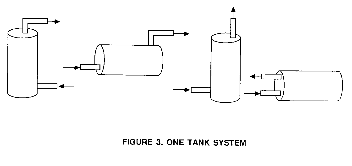
The pipes must slope upward from the collector to the storage tank so that air cannot become trapped and stop the flow. The rising column of hot water in the transfer pipe leaves the collector at opening B and enters the tank at opening A.
Water in the collector must have a continuous upward path to the storage tank. Therefore, all pipes entering the tank from the collector must have a continuous upper slope along their full length. This will prevent air bubbles from forming in the cold or hot water pipes. Air will pass through the sloping pipes into the hot water storage tank. A continuous rise at an angle is better than a vertical rise followed by a horizontal run. Long horizontal runs should be avoided. A continuous upward slope (1-3 centimeters) is needed in the system from the bottom of the storage into the top of the tank. This method will not work because any air in the system will collect in the horizontal pipes and will impair the water circulation.
<FIGURE 3>
One way to overcome this problem is to weld a 3/4 inch iron pipe coupling onto the upper 1/3 portion of the tank. The tank drain opening can be used for the cold water inlet or another 3/4 inch iron pipe coupling can be welded about 3 inches from the bottom of the tank.
If it is not possible to weld an opening to prevent trapped air, a bleeder tube can be used to bleed air from the system. The air bleeder line must be of small diameter to prevent a siphoning problem which would occur with larger diameter tubing.
<FIGURE 4>
Galvanized iron, copper, or even plastic pipe can be used to construct the transfer pipes. For a collector 3 square feet, two transfer pipes one inch in diameter are needed. If the pipes are smaller in diameter, thermosiphoning will start later in the morning and earlier in the afternoon because higher collection temperatures will be needed to drive the flow.
Transfer pipes must be well insulated in order to maintain the high temperature of the water coming from the collector. By locating the collector close to the tank and reducing the length of the transfer pipes, the total surface area through which heat can be lost is reduced. The pipes must also be able to withstand continuous pressure from a central water system.
The storage tank is the reservoir that holds the heated water from the collector, making it available when needed. The tank should be glass-lined or plastic-lined to stop rust. The storage tank must be located above the collector. The minimum effective distance between the storage tank and the collector is 24 inches. Below this distance, natural circulation will not work.
The actual size of the tank depends on hot water consumption. The tank should be made large enough to provide a day's hot water needs for each person. A sample formula for determining tank size is as follows:
1) Hot water demands per person per day = ____gallons. 2) Number of people in household = _gallons. 3) size of storage needed (1x2+20% (1x2))=____gallons.
Note: For an all-solar system, this capacity should be doubled.
Collector size is proportional to tank size. A good general rule is one square meter (39 1/2 square inches) of collector area for 41 1/2 liters (11 gallons) of hot water desired.
The tank can be placed either horizontally or vertically, although an upright position is best since more hot water can be drawn before the colder water begins to flow out. The higher the tank is from the collector, the further the tank can be moved horizontally away from the collector. A convenient formula is two horizontal feet for every foot of vertical pipe from the collector to storage tank.
The storage tank must be well insulated to reduce heat loss. It should be, if possible, within a building. Before mounting the storage tank, the installer should consider that each gallon of water weighs 8.33 pounds, and the structure on which the tank rests should be capable of supporting the required weight of both water and tank.
Whether one or two tanks are used, solar energy serves to preheat the household water. At night and on cloudy days a conventional back-up heater can bring the storage tank up to the desired temperature. On sunny days, the back-up heater should remain off.
Pumped Systems
The next most common solar water heating system is called a pumped system, also called an open system or a direct system because the system circulates potable water under utility pressure directly through the solar collectors and into storage. A pumped system is used in cases where piping runs are too long or there is no position for an elevated tank. The storage tank is placed below the collector and the pump-1/10 horsepower or less-is used to move the water from the collector to the storage tank and back again. The collector has a higher efficiency with an assured steady flow of water.
<FIGURE 5>
Freedom in the system layout allows for greater flexibility in the placement of the storage tank and collector. The collector and its piping form a single circulation loop tied into the host water storage tank. In this system, for instance, the collector can be mounted on the roof, the storage tank in the basement, and the water faucets on the first floor.
This system operates by sensing the temperature difference between the collector and the storage tank. A differential thermostat that has two sensors-one near the collector outlet and one near the tank outlet-senses when the collector is a certain amount hotter than the storage tank (normally 8-11 degrees Fahrenheit). This automatic controller senses the temperature difference, turns on the pump, and circulates water from the cold storage tank to the warm collector. This process continues until the temperature at the bottom of the tank gets to within 3-5 degrees Fahrenheit of the collector temperature. Then the pump shuts off and circulation stops. A much less expensive alternative is a thermostat set to activate the pump when the collector reaches a preset temperature, about 130 degrees Fahrenheit, or to turn off the pump when storage tank reaches a predetermined temperature of about 160 degrees Fahrenheit.
As hot water is drawn from the back-up tank it will be replaced with cold water, thereby reducing the temperature of the storage tank. When the temperature of the storage tank drops enough to trigger the controller, the controller will turn on the pump and start water circulating through the collector again. Once the tank is brought up to temperature the system will turn off.
Freeze-protection for this system involves two methods. The first method is to drain the collector when a freeze condition occurs and is called "drain down." The "drain down" method automatically drains down the collectors and any exposed piping by operating a differential thermostat that activates two two-way selonoid valves. An added feature includes a maual "drain-down" in case of a power failure.
The second method is called "circulating" and simply starts the pump to circulate warm water from the storage tank to the collector when the collector temperature reaches 38 degrees Fahrenheit and to continue pumping until the collector reaches about 50 degrees Fahrenheit. In real cold climates it is possible that all the energy in the storage tank will be depleted in trying to keep the collector from freezing under cold conditions and thereby cause a system failure.
To prevent reverse circulation or thermosiphoning at night or on a cold day, a check valve is installed in the collector return line to the storage tank to prevent flow from the hot tank to the cold collector.
The pumped system like the thermosiphoning system can be used with an electric or gas back-up system. Both tank and collector must be designed to withstand twice municipal water pressure.
The pumped system is also called an active system because it involves complex and interdependent components. The collectors, fluid transport systems and heat storage containers require a network of controls, valves, pumps, fans, and heat exchangers. They are generally more appropriate for apartment buildings, schools, hospitals, and office buildings than for single-family dwellings. In some cases, the active system can consume more energy in running the pumps and controls than the solar system saves.
Unlike the thermosiphon system, the problem of trapped air is eliminated as the pump can force the air through the lines into the tank where it can then be released at the faucets.
This type of system is generally more expensive than the thermosiphoning system. However, the longer life, lower risk, and performance make this system marketable, and therefore more appealing.
The most effective method of protection against freezing the collector is the "closed system" or the use of an antifreeze and water solution in the collector piping. This heat exchange fluid delivers heat from the solar collector to the storage tank. One form of heat exchanger is a coil of copper tubing immersed in the storage tank. The coil is connected to the storage tank to form a single "closed" flow loop.
The major advantage of this system is its durability as a result of reduced corrosion. The efficiency of this system depends on heat exchanger design, surface area, and type of fluid used. A glycol-based antifreeze water mixture is most commonly used. It is similar to that used in automobiles. Corrosion inhibitors in the fluid protect the pipes. However, in time glycol-based antifreezes become corrosive and must be replaced.
Operation of this system is relatively trouble-free. However, the designer must be careful that the fluid does not leak into the storage tank. Antifreeze is a very toxic substance and must never enter the water supply. A common way to overcome this problem is to wrap the heat exchanger around the storage tank. The entire tank and heat exchanger is then well insulated with adequate blanket insulation.
To control collector pressure and prevent vapor locks, some special and expensive accessories not needed on open systems are required on closed systems. These include:
1) an expansion tank, 2) a special low-pressure relief valve, 3) a purge valve for use during filling, 4) a pressure gauge for filling, 5) expensive oil or antifreeze filling, and 6) an installer possessing special equipment for filling the system.
"Breadbox Systems"
An efficient type of water heater that can be used in most areas is the "breadbox" solar water heater. The breadbox solar water heater combines solar collection and water storage functions in one unit. It is usually used to preheat water for a conventional water heater. Placing it as close as possible to the back-up heater keeps pipe runs short, reducing heat loss. As with all solar hot water systems, pipes carrying hot water must be well insulated. To allow for repairs and regular maintenance, the plumbing should be arrranged so the breadbox can be bypassed if necessary. The breadbox should also be equipped with a drain.
<FIGURE 6>
The air venting valve is opened to release air from the system when filling the tanks and to release trapped air when in operation. The vacuum relief valve opens to prevent a vacuum within the system while draining it. A temperature gauge installed on the hot water outlet between the tank and the house can indicate when to shut down the system to prevent freezing. When the temperature consistently approaches freezing, the system should be drained.
Flexible copper hoses are the easiest way to connect tanks in double tank systems. When connecting copper tubing to steel tanks or galvanized metal and copper, the installer should always use dielectric connections to reduce corrosion. The collector storage system should be drained annually and checked for sediment and leaks.
The tank in the breadbox can be used as the storage tank wood fire heat exchanger, making it an ideal combination of solar and wood water heating. In frigid areas, a wood fire during winter can ensure freeze protection. With such an auxilliary heating setup, there is a danger of overheating and consequent steam explosion. A pressure relief valve must be included in the system.
III. CHOOSING THE TECHNOLOGY RIGHT FOR YOU
The choice of a solar water heater depends upon the resources available and the application for which it will be used. The heating systems can be summarized as follows.
The choice among solar collector technologies depends on cost and on the amount of heat required f or the specific application. The trickle collector is a simple, low-cost option, but it cannot achieve high water temperatures. The flat plate collector is more efficient but requires additional expenses for tubing. To achieve high water temperatures, some type of concentrating collector must be used.
The pumped and secondary fluid systems both offer the advantage of continuous circulation at a more rapid speed than the direct thermosiphon system. However, they do require an external source of power, and they both require pressure valves.
The overall efficiency of the open pumped system is higher than the closed secondary fluid system, and its cost is considerably lower. Fluid in the secondary fluid system requires more pumping energy than does the same amount of water in an open system. The heat exchanger in a closed system adds resistance to the circulation of the fluid, thus increasing the energy required for pumping. Furthermore, the capacity of the fluids to absorb heat is less than that of water, so more fluid must be pumped through the system for the same amount of heat exchange. On the other hand, the secondary fluid system is extremely durable.
The breadbox system is a highly efficient solar water heater for use in tandem with a conventional water heater or as the storage tank for a wood fire heat exchanger. It does not require the use of transfer pipes, but does require venting and valves to releave pressure.
In general, solar heating has distinct advantages over the traditional technologies that are based on coal, oil, or gas. As the supply of fossil fuels dwindles, environmental damage further adds to the indiscriminate use of these fuels. Nuclear power threatens to bring a new round of pollution and waste. An answer to energy deprivation is the use of solar energy to heat and cool our homes as well as to supply a percentage of the world's electrical and hot water needs.
BIBLIOGRAPHY
Anderson, B. and Riordan, M. The Solar Home Book, 1976.
Fritz, D. "Solar Water Heater," Village Technology Handbook, VITA Inc. (1970).
Hasting, A. Solar Water Heaters, 1970.
Living Alternatives. Can You Use a Solar Water Heater? Vol. 2, No. 4, Jan. 1981.
National Center for Appropriate Technology, Breadbox Solar Hot Water Systems. 023758. XVIII-DE-2, p.3.
New Mexico Solar Energy Institute Solar Fact Sheet. Breadbox Solar Water Heaters. 1980 XVIII-DE-2, p.3.
Praudyogiki, G. Solar Water Heating, Vol 1, No. 2. 1981.
Ridenour, S. Homemade Solar WAter Heaters, ND 221-239, XVIII-DE-2, p.3.
Schumacher, D., McVeigh, C. Solar Water Heaters. 007545 XVIII-DE-2, p.3.
Sussman, A., Frazier, R. Handmade Hot Water Systems, 1978.