This article is from ECHO Asia Note #19
[Editor’s Note: With the increasing popularity of alternative and renewable energy sources that are derived on-farm, we have had many inquiries into the applications of farm-derived biogas for powering small machinery. This article seeks to address one of the possible uses of manure- derived biogas: powering a small diesel engine.]
Author’s Introduction
Many of the remote rural communities with which LIRE works live in ‘off grid’ locations, i.e. places with no access to electricity. My first introduction to development work was in such a community, in a rural hospital north of Vientiane, Lao People’s Democratic Republic. Although it was situated off-grid, the hospital had recently installed a 10 m³ fixed volume underground biogas digester to use for cooking in both the hospital and the doctor’s house. The feedstock used came from the 20 head of cattle owned by the hospital. The hospital also had a small Chinese-made, 10 kW diesel engine, which had been hooked up to a single phase generator to provide lighting and to be used for charging mobile phones for a few hours in the evening.
My task was to use the gas from the biogas digester to run the diesel engine; this started a development program that was both frustrating and enlightening at the same time. These crude first attempts were further augmented with a similar project I undertook later during my time with the Laos Institute for Renewable Energy (LIRE) on behalf of FACT Foundation.
In this article, I share the lessons I have learned in this development process; it is by no means a definitive account and may not be 100% scientifically correct. But these are real lessons learned from running trials in remote locations with very limited resources. I have also attempted to keep it rudimentary and avoid technical jargon.
Summary
It IS completely possible to run a diesel engine on biogas; however, a number of considerations must be taken into account before it may be considered a serious option in a development program. This article will explore some key considerations when attempting to burn biogas in a diesel engine.
Basic Background Information
First, it is important to distinguish between different types of diesel engines. Diesel engines are pretty similar in operation and have been around since Rudolf Diesel first developed the engine in the 1800’s. They rely on compression ignition (CI) of a small amount of diesel fuel that is injected into the ignition chamber. Simultaneously, a valve is opened to allow air into the ignition chamber. The valve is closed and the piston compresses the mixture. When the air/fuel mix reaches its ‘stoichiometric point’ (i.e. the point at which the ratio of fuel:air is enough to chemically combust), it ignites under the pressure created when the piston reaches Top Dead Centre (TDC), which is normally around a 17:1 compression ratio. As the mixture ignites, the piston is forced downwards, driving the connecting rod and thus turning the engine. Modern diesel engine cars have sophisticated fuel systems and engine management systems that make the engine very efficient but more ‘highly strung’; the introduction of an impure gas (such as biogas) into the equation will result in problems.
The small mechanical bull motors found throughout Asia, more commonly known as tok toks, are a simpler, cruder design and have a simple ‘common rail’ fuel injection system. Even simpler are the Listerstyle engines, which are built to withstand just about anything thrown at them. The stationary nature of a biogas digester means that the power generation will be stationary, so is more suited to a “tok tok” or Lister-type engine that can be mechanically linked to the output (generator/pump/ machinery).
Fuel Systems
Unlike gasoline engines, diesel engines do not have a throttle, and instead use a governor which regulates the speed of the engine. In more sophisticated engines, the governor can be electro/mechanical, electronic/mechanical or hydro/mechanical. However, the tok tok engine uses a simple but effective rotating, purely mechanical governor. The function of this governor is to maintain the speed of the engine regardless of load (other governors can maintain load regardless of speed, but again, these are more sophisticated and more costly). The governor will regulate the fuel demand to maintain the pre-set speed. The engine speed is adjusted by the ‘rack,’ which is set by the operator to the desired speed. In effect, the operator uses the rack position as a throttle control, although its function differs from a gasoline engine by regulating the fuel rather than the air, but the end result is similar. This is important to know, because when we introduce biogas into the system, we replace the ‘inert’ air with an explosive mixture, thus completely rearranging the physics involved in the combustion process. Fortunately, we do not all have to be experts in thermodynamics to get it working; in reality, the systems tend to balance themselves out and ratios of explosive mixtures happen automatically.
Engine Types
Biogas does not self-ignite under compression, so a small amount of diesel fuel is still required for the ignition. From desktop research and my own experiments, the optimum ratio achievable using biogas as the main fuel seems to be 20% diesel fuel to 80% biogas. Adding a small amount of diesel fuel to the mixture is also important for lubricating the fuel injectors, which is a secondary function of the diesel fuel.
If you require an engine to run on pure biogas, a ‘gas engine’ (not to be confused with a gasoline engine) is required. A gas engine is essentially a diesel engine with a spark ignition, as contrasted with a true diesel engine, which uses compression for ignition of the fuel/air mixture. Gas engines are available in relatively small sizes, but they tend to be more expensive and harder to source than regular diesel engines. Because gas engines have an ignition system, they tend to be more complex. The beauty of a diesel engine is its simplicity, relying on purely mechanical elements to function. The introduction of coils, spark plugs, ignition timing, etc. results in a complex system with increased maintenance and more possibilities for mechanical failure.If you require an engine to run on pure biogas, a ‘gas engine’ (not to be confused with a gasoline engine) is required. A gas engine is essentially a diesel engine with a spark ignition, as contrasted with a true diesel engine, which uses compression for ignition of the fuel/air mixture. Gas engines are available in relatively small sizes, but they tend to be more expensive and harder to source than regular diesel engines. Because gas engines have an ignition system, they tend to be more complex. The beauty of a diesel engine is its simplicity, relying on purely mechanical elements to function. The introduction of coils, spark plugs, ignition timing, etc. results in a complex system with increased maintenance and more possibilities for mechanical failure.
Biogas Background Information
Biogas can be fed directly into the air intake of the diesel engine, and will be

Figure 1. The diesel engine fuel system
consumed. Because of the rack injection system, the rack will adjust automatically to the input (Figure 1). There may be a change in the engine’s ‘tone’ as it adjusts to the intake of the biogas. The engine may exhibit increasing and/or decreasing revolutions per minute, depending upon: a) the condition of the engine and b) the condition of the biogas. But the important thing is that whatever the tone and RPM, the engine should continue to run on its own.
Biogas is a combination of gases. Methane (CH4) is the most important for energy production, and consists of somewhere between 40% and 75% of the total gas volume. The other gases vary in quantity (Table 1).
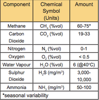
Table 1. Constituents of Biogas
Long-term Effects of Biogas on Engines
Although the majority of biogas constituents are benign, the long-term exposure of the engine’s material components to hydrogen sulfide (H2S) will be detrimental to the mechanical elements of the engine. If the working life of the engine is a consideration, the H2S should be removed from the gas (scrubbed). Other major components of biogas, such as water vapor (H2O) and carbon dioxide (CO2), do not cause any irreparable damage to the engine. However, CO2 is a large component of the gas and will make the ignition inefficient. Water vapor is also harmless, but if it condenses after use and is left for a long period of time, iron oxide (rust) will form on the cylinder components.
Engine Condition
In my initial experiments at the hospital in Lao PDR, the engine was in a poor state of repair. Equipment was not available to measure the compression ratio, but I estimated it to be as low as 13:1 or 12:1. The result of this was disappointing, as I was only able to achieve a maximum fuel ratio of 20:80 (20% biogas to 80% diesel).
Biogas Consumption Tests
I measured the ratio of the biogas:diesel consumption using a large syringe

Figure 2. Syringe for measuring diesel consumption, with ‘swirl chamber’ also shown.
 Figure 3. Chinese-made laser tachometer for $25 did the job well.


mounted in the fuel line (Figure 2). The syringe was filled with a known quantity of diesel fuel. The engine was run and the speed measured using a tachometer (commonly referred to as a tacho - Figure 3).
Tachos can be difficult to source in some countries, and it was impossible to get one in Laos. I bought a Chinese-made laser tacho on e-bay for $25, which seemed to work well. The consumption of the known quantity of diesel (in the syringe) is timed using 100% diesel at a set engine run speed. Then the test is repeated by feeding biogas into the engine in an effort to use as little diesel and as much biogas in the mix as possible.
In my early experiments, I modified the air filter by inserting an inlet with a valve and a hose connector into the air filter housing (Figure 4). The biogas was then connected directly from the biogas digester to the air intake by a flexible hose. The bigger the hose, the better; in our case we used a ¾” hose with a ¾” valve. The engine should be able to start on biogas but, for the sake of practicality, I found it easier to start the engine on pure diesel and then open the biogas valve on the air filter.
During my early experiments, I also created and tested a ‘swirl chamber’ (Figure 5) in order to better mix the oxygen and biogas before combustion; I constructed this from a steel tube with a diffuser in the middle (Figure 5). The reason that you might use a ‘swirl chamber’ is that methane molecules are tiny compared to those of oxygen. In some online articles, a ‘swirl chamber’ is recommended, and they are used in some modern cars. In my latest experiments, I have not found them to make a difference in performance. However, they might help in some instances, and you might consider trying one if you are having problems with efficient combustion.

Figure 6. Old diesel engine in poor condition.


The above experiments were undertaken using an old diesel engine in poor condition (Figure 6). Another test was undertaken using a relatively new single cylinder Kubota engine (Figure 7). The results were more impressive using the new engine, because the engine ‘took off’ as soon as the biogas valve was opened. The rack was adjusted to a point where the engine tone (speed) was similar to that of the engine running pure diesel. The resultant smooth operation of the engine on biogas was obtained with a ratio of approximately 80% biogas to 20% diesel fuel mixture.
The biogas pressure to run the diesel engine does not need to be high, and the gauge we were using was not of high quality, but I estimated the biogas pressure to be at about 10 kPa (about 1.5 psi). The action of the engine will be enough to draw the fuel into the system, so a pressurized system is not required to run a diesel engine.
The engine was only run for a short period of time, because it was consuming an alarming amount of gas.

Figure 9. Modification for air inlet.
Location of Gas Inlet
Be sure to introduce the gas into the engine at the correct location. In my experiments, I introduced the gas into the air filter. After trialing this several times and speaking to others who have undertaken similar experiments, I realized that this was incorrect. The biogas inlet should be placed in the air intake manifold, just before it enters the engine (Figures 8 & 9). You can attach the biogas feed to this intake by cutting a hole and welding a threaded socket onto the inlet pipe, as shown in Figure 9.
The Lab at km 19
I did another research project with LIRE, this one to calculate the amount of energy that could be generated from a known input of feedstock. The lab was located at a pig farm just outside Vientiane at km 19. The farm also distilled a local rice whiskey called ‘Laos Laos’. The biogas produced by the pig farm was used for cooking and to fire the stills. They then used the ‘mash’ to feed to the pigs. This almost created a complete cycle of inputs and outputs, although in reality there were more inputs than just mash and biogas.
By measuring both the inputs and the outputs of the biogas production, we could calculate how much manure (in this case pig manure) would be required per kWh of energy produced using a diesel engine running on a mixture of diesel and biogas. The ‘lab’ consisted of an 8 m3 fixed-volume underground biogas digester. After production, biogas was fed into a 5 m3 biogas balloon for storage. For the power output, we used a small 4.8 kW single-cylinder Chinese-made engine. We measured output power using a ‘Prony brake’ mounted on the output shaft, a simple forerunner to the modern dynamometer.
[Note: Details of the Prony brake have not been included in this report. If more information on the ‘Prony Brake’ is desired, please contact the author.]
As part of our trials in Vientiane, we tested the effectiveness of ‘scrubbing’ the gas before it reached the engine. With the tests, we hoped to determine the most efficient and practical method of scrubbing the gas in a rural context (Figures 10 & 11).

Figure 10. Biogas lab schematic

Figure 11. The biogas ‘lab’
Biogas Scrubbing
I know of two effective and accessible ways of removing, or ‘scrubbing’, H2S (Hydrogen Sulfide), both of which can be applied using appropriate technology. Industrial scrubbers do exist, but their cost and availability would probably rule them out in a rural context. For an acceptable quality of gas, you will want less than 100 ppm (parts per million) of H2S in the biogas. Generally speaking, it will require more scrubbing than you might think.
Scrubbing Using Sodium Hydroxide
Sodium Hydroxide (NaOH), better known as ‘Caustic Soda’ or ‘Lye’, is a

12. Water tower schematic.


comprehensive scrubbing medium that will remove CO2 as well as H2S. Sodium hydroxide is widely available even in remote rural communities, and can usually be purchased at a local building supply store. In order to scrub biogas with sodium hydroxide, you will need to build a ‘water’ tower; this can be constructed from locally available materials (Figures 12-13). In the tower, the gas is bubbled through a solution of water and Sodium hydroxide at a ratio (by weight) of 3:1 water to NaOH. The gas is pumped through the water tower into a manifold that has a series of small holes (Figure 12). The idea is to create bubbles that are as small as possible, thus increasing the surface area of the gas as it is passed through the solution of water and sodium hydroxide. A chemical reaction occurs, causing the H2S and CO2 to precipitate out and form a slurry at the base of the tower.
When using this approach, we became aware of serious drawbacks to the process:
- The design of the water tower made it awkward and cumbersome, both to get the solution in and to get the dilute with the slurry out. Although in the end, the biogas was scrubbed of H2S and CO2, we were left with a toxic slurry of which to dispose.
- Handling caustic soda is dangerous, and protective gear (gloves and glasses) MUST be worn (Figure 14). Safety equipment will be much harder to access than caustic soda. Also, there are potential cultural obstacles to overcome in the use of PPE (Personal Protective Equipment). Note: it is handy to have a bottle of vinegar on hand, because vinegar is acidic; if caustic soda is spilled on the skin, vinegar can be applied to neutralize the strong alkaline.
- The biogas must be pressurized enough to be able to push the gas through the water tower (i.e. there must be enough ‘head’ to do this). In normal operation, the pressure in the biogas balloon is likely insufficient to overcome the head; therefore, an additional gas pump must be added. In a rural location there might not be access to 240V mains power or a gas pump to add the extra pressure needed to use the water tower.
In our experiments, we circulated the 5 m3 of biogas through the tower and back into the storage balloon. Although final readings weren’t taken, we estimated that this would take 10 hours to complete the scrubbing cycle, and result in several kg of toxic slurry.
Scrubbing Using Iron Oxide (Rust)
An iron oxide (rust) scrubber is the usual ‘appropriate’ method for scrubbing biogas, because this kind of scrubber is simple to create. Rust consists of

Figure 15. Schematic of iron oxide scrubber.
hydrated iron oxides (Fe2O3•nH2O) and iron oxide-hydroxide (FeO(OH)•Fe(OH)3). As the gas is passed over the rust, a chemical reaction occurs, and the H2S precipitates out of the biogas (Figure 15). Unlike the sodium hydroxide scrubber, however, this method does not scrub the CO2.
The main challenge with this method is accessing steel or iron as a feedstock for the scrubber. Ideally, one would look for the shavings from a machine shop, often referred to as ‘swarf,’ ‘shavings,’ or ‘filings.’ Old ball

Figure 16. Iron Oxide gas scrubber.


bearings are ideal, as they have a large surface area to volume ratio, but they may be difficult to acquire in any useful quantities. Fine particles of steel ‘filings’ are not useful because the gas must be able to pass through the tube packed with the filings. Once the swarf has been acquired, it must be allowed to rust, with two or three weeks of exposure to the elements. (It is quite possible that the swarf will have been oiled originally to prevent the base material from rusting, so any swarf that is acquired must first be thoroughly degreased using a soap solution). After a few weeks of exposure to the elements, there should be a generous coating of rust on the swarf. The swarf should then be packed into a PVC tube (I used a tube that was 1.4 m long with 75 mm diameter) with an outlet and inlet at either end (Figures 16, 17). A couple of perforated plates helped with the assembly by creating a column of swarf in the PVC tube (Figure 18). The swarf in the column allowed the gas to pass freely, but had enough surface area for the iron oxide and the H2S to react. I suggest using removable end caps, as they will need to be removed to change the swarf.
The only real operating issue that I found with this method was the difficulty of making the tube air/gas tight. In the end, I concluded that, because of the low pressure, very little of the gas would escape. Unlike the sodium hydroxide method, no gas pump was needed to force the biogas through the swarf. I measured the effectiveness of the scrubbing afterward by bubbling the gas through a lead acetate solution, and measuring the amount of resulting lead sulfide (i.e. the sulfur not removed during the scrubbing) (*For details about the lead acetate test, please contact the author). Based on the lead acetate test, I concluded that four further stages of scrubbing would be required to remove all sulfur dioxide. Both approaches would require feasibility studies.
Scrubbing the Water Vapor
Although water vapor is not problematic for the ignition process, the introduction of water vapor into the cylinder could cause condensation and would promote rusting. Therefore, it is considered advantageous to add a ‘water trap’ before biogas enters the engine.
A crude water trap can be made using a steel tube with an inlet at one end and an outlet at the other. The steel tube must be placed in a location that is cooler than the gas in the tube, thus causing the water vapor to condense onto the inside of the tube. How this will be achieved depends very much on locally available cooling sources. Cooling sources such as underground thermal cooling, flowing water, etc. may be very difficult to find in rural situations. The tube needs to be about 6 meters long and must also have a drain cock to remove the condensed water. In my experiments, no ‘cooling source’ was available, so I decided to not remove the water vapor. Even without water vapor removal, the biogas was combusted in the engine without problem. However, longterm usage of un-scrubbed biogas in diesel engines may result in rusted cylinders and mechanical failure.
How Much Power can be Produced Using Biogas?
In many respects, the production of biogas is more of an art than a science. There are many variables to consider. When the gas is being used for cooking, the vagaries of biogas are mainly masked by its crude conversion (by combustion) to heat and light. When biogas is used as fuel for an engine, variations become more apparent and significant. Keep this in mind when reviewing results from tests of biogas as an engine fuel (as I have outlined below). In other circumstances, with other methods of biogas production and feedstock utilization, a completely different set of results might be obtained. Use the following results only as a rough guide.
Data from Tests and Empirical Results:
1 kg manure = 60 - 100 liters of biogas
An estimated 550 liters of CH4 are required per kWh of power produced at engine output shaft
Typically, biogas contains 60% methane on average; meaning 900 liters of raw biogas would be needed per kWh of energy
So 9 - 15 kg of manure would be needed per kWh of electricity
In Real Terms
If you ran a 10 kW generator for 3 hours, the amount of energy produced would be 30 kWh, requiring 270 - 450 kg of manure to be fed into the biogas digester as the feedstock.
Remember that this is the output from a diesel engine. For power generation, the output shaft needs to be hooked up to a generator via either a belt and pulley or chain and sprockets. Please be aware that electromagnetic resistance in the generator windings will also require energy input to overcome, again reducing the overall efficiency. For small generators (up to say 50 kW), allow a further 15% reduction in usable power.
Is Biogas Practical for Power Generation?
It is possible to use biogas for power generation. However, a number of practical considerations need to be addressed. Running an engine on biogas requires a lot of biogas, which requires a lot of feedstock, and hence a lot of labor and infrastructure. The technical requirements, materials needed for scrubbing, and other inputs require a significant technical and labor investment.
I conclude that using biogas to power a diesel engine for electrical generation and/or mechanical work should be considered as a last resort rather than a first option, especially if grid power is available.
YouTube video: http://www.youtube.com/ watch?v=nKFe7N7Q4iE

[Gordon Hirst: Engineering consultant & appropriate technology specialist; Chief Engineer, Maejo University School of Renewable Energy. gordon.e.hirst@gmail.com]