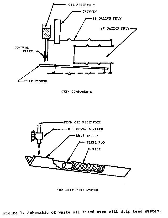
This simple, low-cost bakery oven is fueled by waste, automotive crankcase oil. The design has undergone extensive testing. It is designed to be built from locally available materials.
This oven is capable of maintaining a 160 degrees C to 190 degrees C baking temperature on .946 to 1.4 liters of waste oil per hour depending upon chimney draft. This oven is a result of a student design project by University of Maryland students under the direction of VITA Volunteer Clifford L. Sayre. The other members of the project are: Leon Chuck, Richard Freeman, Morris Hoover, Maureen Houle, Barry Kornett, and Thomas Sieber.
Please send testing results, comments, suggestions, and requests for further information to:
VITA 1600 Wilson Boulevard, Suite 500 Arlington, Virgnia 22209 USA Tel: 703/276-1800 * Fax: 703/243-1865 Internet: pr-info@vita.org ISBN 0-86619-164-X Revised April 1984
INTRODUCTION
The development of small-scale industries in many countries has been hampered by the scarcity and cost of high-grade fuels. This is particularly true for bakeries in small villages, which must presently rely on the use of low-grade fuels such as peat or dried dung for economical operation. At the same time, large amounts of used automotive crankcase oil are discarded. Waste motor vehicle oil is usually dumped into the nearest field or river. However, waste oil is a refined petroleum product, which with special handling has considerable potential as an alternative fuel source.
The oven design in this bulletin makes use of waste oil without preheating or mixing with other, more expensive fuels. The cost range for building this oven is from $25 to $60 (US, 1980).
<Figure 1>
TOOLS
* Acetylene torch * Metal shears * Drill and bits * Metal punch (3.175cm) * Saw for cutting wood * Hacksaw * Pliers * Scribe * Hammer * Screwdriver
MATERIALS
- Drum, steel, 55-gallon (1)
- Drum, steel, 42-gallon (1)
- Tin can, one-gallon (1)
- Sheet metal, medium (26) gauge, about .058cm thick (approximately 122cm x 122 cm)
- Steel angle iron, 2.54cm (183cm long), 122.04cm left for trough
- Threaded steel rod, .95cm dia. (25.4cm long)
- Steel strap, .63cm wide x 15.24cm long x .32cm thick
- Galvanized pipe, .31cm, each end threaded 5.08cm (38cm long)
- Galvanized reducers, 1.27 to .63cm (2), or fittings to serve as nuts to hold above galvanized pipe to tin can fuel tank
- Galvanized coupler, .63cm (1)
- Petcock (auto radiator drain valve), .63cm (1)
- Wood lathe, 2.54 x 1.27 (25.4cm long)
- Cheesecloth or other loosely woven cloth (183 sq cm)
- Rubber or plastic washers, flat, .63cm (2)
- Screws, wood, 2.54cm (2)
- Screws, metal, .31cm (8)
- Nuts, .95cm x .15cm (8)
CONSTRUCTION
Step One:
Using the acetylene torch, cut the top off of the 55-gallon drum.
Step Two:
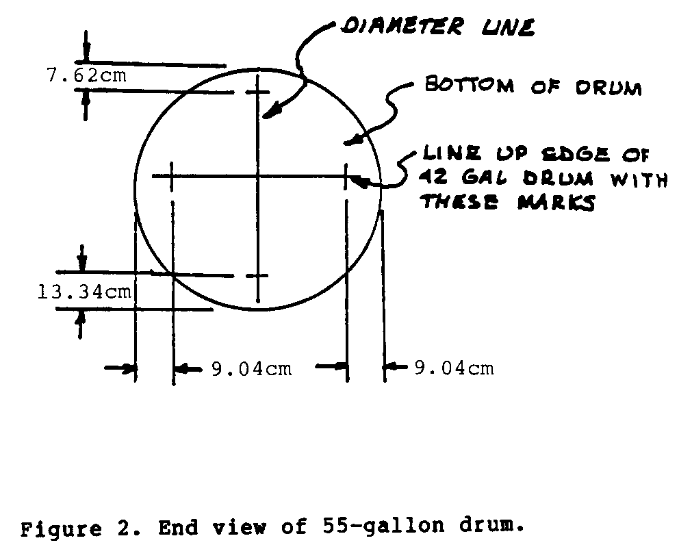
Turn the drum upside down and, starting with any diameter across the bottom, scribe the locating lines as shown in Figure 2.
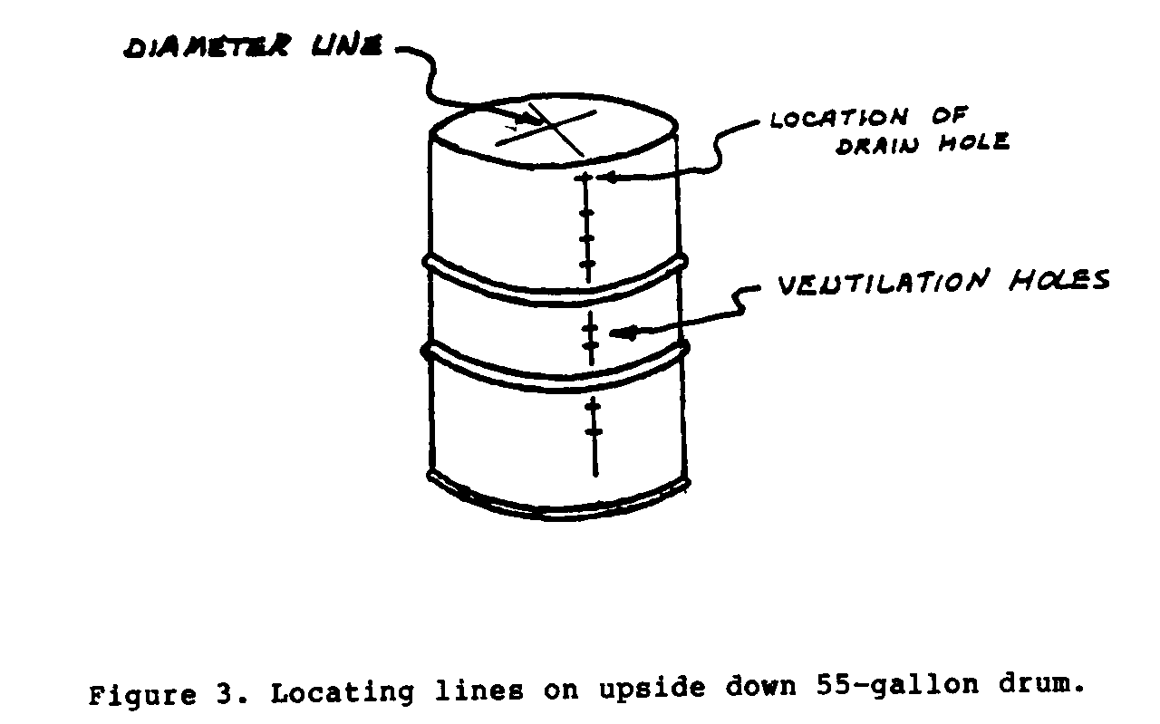
Continue the diameter line on the side of the drum to locate the ventilation and drain holes, as shown in Figure 3.
Step Three:
Place the 42-gallon drum on top of the upside down 55-gallon drum so that the edge of the 42-gallon drum lines up with the locating lines scribed in Step Two (as shown in Figure 2).
Scribe a line around the circumference of the 42-gallon drum.
Remove the 42-gallon drum and set aside.
Step Four:
Using either a hacksaw or an acetylene torch, cut a hole in the 55-gallon drum on the line scribed in Step Three.
Make the cut as neat and accurate as possible as the piece cut out will be used as the door of the oven.
Step Five:
Using either the 3.175cm punch or the torch, cut a drain hole as close to the bottom of the 55-gallon drum as possible. Center this hole on the locating line scribed on the side of the drum, as shown in Figure 3.
Step Six:
Using the punch or the torch, cut six or seven evenly spaced ventilation holes along the side locating line as shown in Figure 3.
Step Seven:
Using Figure 4 as a suggested locating guide, cut out the sheet
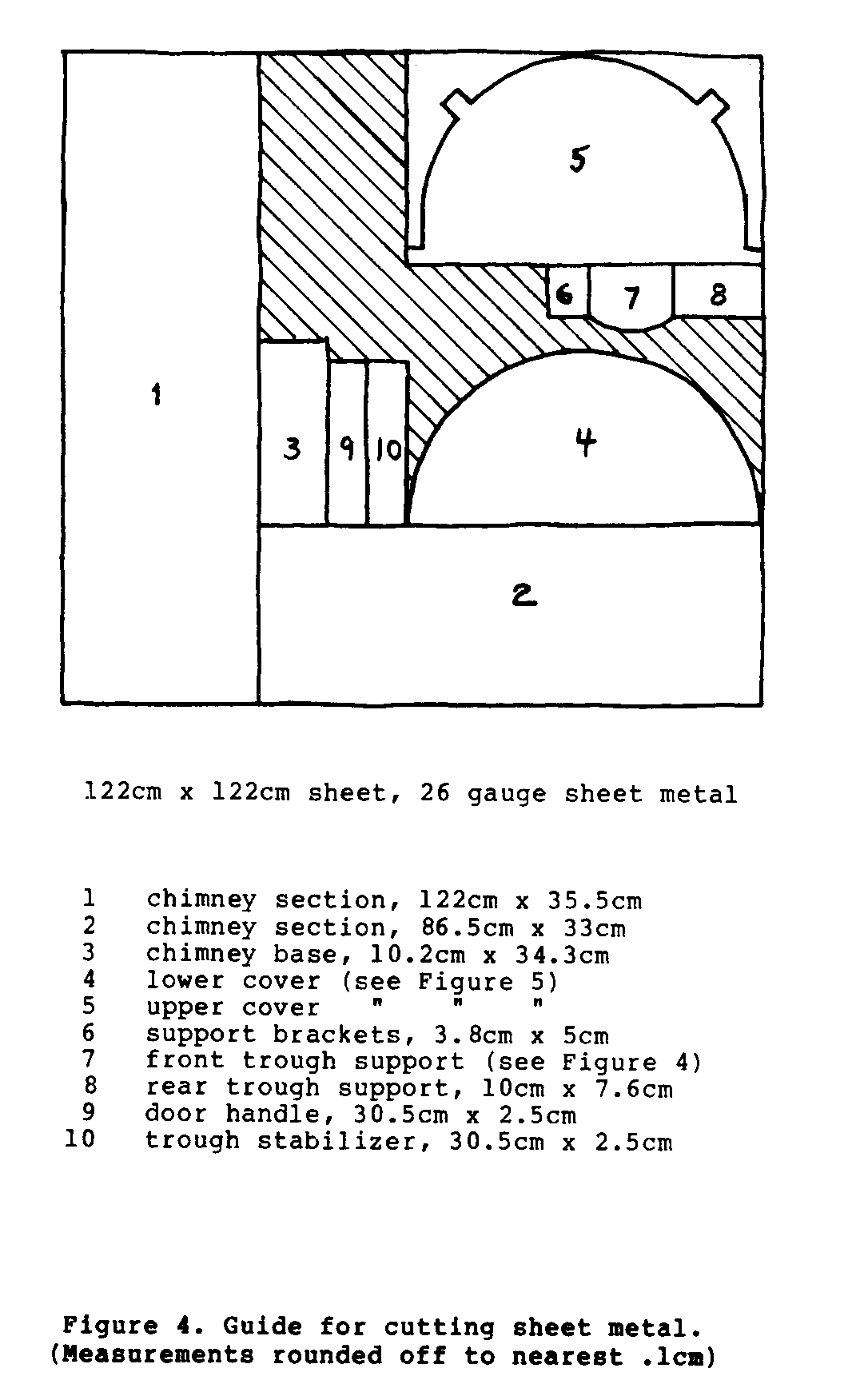
metal pieces for the front and rear trough supports as shown in Figure 5.
Still using Figure 4 as a guide, cut out the sheet metal pieces for the upper and lower covers as shown in Figure 6.

Step Eight:
Braze the support brackets to the sides of the front trough support (see Figure 5).
Step Nine:
Locate the front trough support inside the 55-gallon drum so that the "V" cut in the support is on the same line as the center of the drain and ventilation holes.
Weld this assembly to the drum about 7.62cm behind the drain hole.
Step Ten:
Support the 42-gallon drum on a level surface so that when the 55-gallon drum is placed over it, the top edge of the 42-gallon drum just lines up with the hole cut in the bottom of the 55-gallon drum as shown in Figure 7.
Step Eleven:
Carefully weld the top edge of the 42-gallon drum to the bottom of the 55-gallon drum as shown in Figure 8.

Step Twelve:
Cut a 30.48cm length of angle iron from the 183cm piece.
Step Thirteen:
Turn the drums over (55-gallon drum top side up) and weld the angle iron cut in Step Twelve to the bottom of the 42-gallon drum and the sides of the 55-gallon drum as shown in Figure 9--this
forms the rear support for the 42-gallon drum.
Step Fourteen:
Place the drum with the ventilation holes facing down. Using either the sabre saw or the torch, cut a 10.16cm diameter hole for the chimney in the top rear of the 55-gallon drum, located approximately as shown in Figure 10.
Step Fifteen:
Cut out a 10.16cm x 34.29cm piece of sheet metal (#4 in Figure 4) and form it into a 10.16cm diameter tube. Place this piece
into the hole cut in Step 14 and weld around the circumference as shown in Figure 10.
Step Sixteen:
Cut out the remaining chimney pieces (#1 and #2, as shown in Figure 4). Form these pieces into 10.16cm diameter tubes with a slight taper so the ends can be fitted together to form the chimney.
Step Seventeen:
Weld the seams of the chimney pieces formed in Step Sixteen.
Step Eighteen:
Cut the threaded rod into two 12.70cm lengths.
Step Nineteen:
Cut out a 30.48cm x 2.54cm section of sheet metal and drill two 1.12cm holes in it as shown in Figure 11.
Step Twenty:
Weld this piece inside the 55-gallon drum approximately 5.08cm from the top (refer to Figure 9). Assemble the rear trough support as shown in Figure 11 above.
Step Twenty-One:
Cut the top off the one-gallon tin can. Drill a .95cm hole in the bottom of the can so that when feed pipe is inserted it will be clear of upper cover.
Step Twenty-Two:
Assemble the components of the drip feed system as shown in Figure 9 and Figure 12.

Step Twenty-Three:
Cut two 15.24cm lengths of angle iron and form the reservoir support as shown in Figure 13. Half of bottom part of each
piece needs to be cut away before bending. Weld the supports to the 55-gallon drum as indicated in Figure 13.
Step Twenty-Four:
Cut out a 30.48cm x 2.54cm piece of sheet metal (#9 in Figure 4) and form the door handle. Cut two pieces of wooden lathe to fit inside and outside of the formed handle as shown in Figure 13. Weld the completed handle assembly to the door.
<Figure 14>
Step Twenty-Five:
Cut off three 5.0 8cm lengths of .63cm strap and form as shown in Figure 15.
Step Twenty-Six:
Weld the formed strap pieces to the 55-gallon drum as shown in Figure 16.
Step Twenty-Seven:
Using .31cm sheet metal screws, secure the top cover to the rear of the oven by bending the mounting tabs over and drilling four holes through both the tabs and the side of the drum.
Figure 17 shows a view of the completed oven.

OPERATING PROCEDURES
The beauty of this particular waste oil oven lies in its simple design and ease of operation. Following just a few mandatory operating procedures will allow the oven to be used to its fullest cooking capabilities.
To ensure safe operation, before starting up the oven it is important that:
* The oven is in a semi-enclosed area with adequate ventilation for combustion.
* No combustible materials are within eight meters of the oven.
* The chimney and combustion chamber between the two drums is free of obstructions, carbon build-up, and remaining oil drippings from previous operation.
* The drip-feed system is free of obstructions for easy adjustment of the fuel flow rate.
* An oil collection container is carefully placed to catch all oil overflow from the oven.
Once all of the above precautions are met, begin preparing to start the oven. First, make sure that the drip feed valve is completely closed and that the reservoir is full of oil.
Next, open the drip feed valve, just slightly, to allow a drop of oil to form on the nozzle. This will prime the system for immediate operation at the time of firing.
The most critical of all the start-up procedures involves the preparing of the wick and combustion trough. It is essential that the next sequence of steps is carefully followed.
* Remove the trough from the oven. Clean both the trough and the metal rod completely. Any remaining ash or oil build-up will impede the fuel flow thus severely reducing the oven's efficiency.
* Wrap the entire length of the metal rod in the wick material.
* Place the wrapped rod in the trough.
* Liberally douse the rod and wick with fuel oil so that it is fully soaked.
* Place the trough halfway into the oven combustion chamber so that it is resting on the bracket.
* Light with a match the endmost portion of the soaked wick.
* Place the trough completely into the oven.
* Begin a very slow drip feed into the trough at about one drop per second. This will allow the flame to burn clown the trough, which in turn will raise the combustion chamber temperature to the point of flashing.
* Once the trough is burning down its entire length, increase the fuel flow rate to the point where the single drops are no longer distinguishable and a steady fluid stream has not yet been completely established.
* At this point your oven is operational. Wait fifteen minutes before using so that the peak temperature may be reached.
Once the operating temperature has been reached, make frequent checks upon the drip-feed system and the troughs. It is important that the fuel reservoir be kept at least one-half full to maintain a constant fluid flow rate.
It is also necessary to prevent fouling in the trough. Fouling could lead either to flame burnout or fuel overflow flashing. Fuel overflow flashing will cause uneven and sometimes uncontrollable combustion processes. In this case, it is best to turn off the fuel supply and to allow the internal burning to die out. Then start again.
In closing down the oven, it is best if the fuel supply is turned off and the troughs immediately smothered. This avoids the annoyance of incomplete combustion and its accompanying smoke.
When the oven is cool, it is best if the troughs are then cleaned. This avoids complications such as gumming up or hardening of the oil in the trough. It also facilitates start-up procedures the next time the oven is to be used. WARNING!
Waste oil from engine crankcases or gear boxes can be a useful, low-cost fuel in certain applications. However, users of waste engine oil are warned that the oil might contain lead from leaded gasoline. The lead would be released into the air as the oil burned. It could be a hazard to people working around the oven.
Users of waste engine oil should have the oil tested to find out if it contains lead. The baking chamber of the oven should be sealed tightly to keep combustion products away from the food being baked. The oven should be used out of doors or in a well-ventilated place. The chimney should be high enough to carry combustion products well away from the work area.
Do not use engine oil to fire space heaters or food dryers. Waste oil from electric transformers should not--repeat, not--be used as fuel in any circumstances. Transformer oil contains poly chlorinated biphenol (PCB) compounds. PCB is highly toxic and should not be burned at all. It should not even be handled at all. If you think your waste oil supply might come from electric transformers, do not take chances. Do not burn the oil.