Introduction
 A standard versus load-centered wheelbarrow
A standard wheelbarrow, with the wheel at the front, places about half the weight of the load on the operator. A load-centered wheelbarrow places the wheel in the center of the load, shifting 90% or more of the weight to the wheel instead of the operator. This allows the device to be used for distance hauling on narrow paths.
The load-centered wheelbarrow is an ancient Chinese design. Cargo was placed around and above a large (about 1m diameter) wheel. This allowed operators to transport heavy loads (including passengers) many kilometers on narrow footpaths. An excellent article (De Decker, 2011) and video (The Chronicler’s Tale, 2020), with associated links in the References section, summarize the history of the Chinese wheelbarrow, and the interested reader can find many additional images and designs on the internet.
The bamboo load-centered wheelbarrow
Design features and capabilities
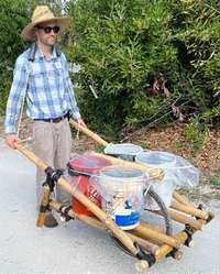
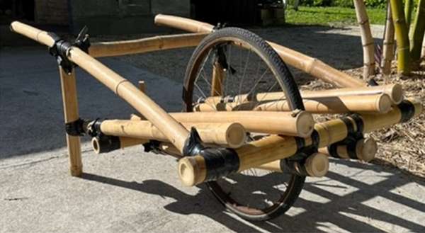
Figure 1. Wheelbarrow at ECHO being used to transport water. Source: Tom Bierma
ECHO developed a design that is scaled down to use a bicycle wheel. This load-centered wheelbarrow, pictured in figure 1 and the focus of this document, can be built with bamboo or other locally available material. Designed to carry water or other material long distances on narrow paths, it is dimensioned to carry four, 5-gallon (19 L) buckets.
Testing demonstrated that 68 L of water could be transported easily on level ground over 3 km by one person. Though the load weighed 68 kg, only 8 kg was bearing on the operator. This could be reduced further by shifting the load forward, but tests were performed with the load centered slightly behind the wheel axle to improve control. A shoulder strap fastened to the handles allowed the 8 kg to be carried easily while maintaining an upright posture. Tests with a standard wheelbarrow found that 25 kg or more was bearing on the operator, depending on the angle of lift.
Steep hills will require assistance from a second person. A rope attached to the front can be used going uphill. Going downhill will require caution as there are no brakes. The bicycle wheel (tire ISO 590/26 x 1 3/8) handled small rocks and roots smoothly.
Design considerations and potential modifications
The wheelbarrow design can be modified to meet local needs, conditions, and materials. If you make modifications or have other design ideas, please share them with us and others in the ECHO Community.
The most important design goal for the wheelbarrow is a cargo structure that is:
- approximately centered on the wheel axle (in x and z dimensions),
- as narrow as practical,
- as low-to-the-ground as practical.
Our design for carrying buckets allowed the wheel to remain exposed. However, for carrying other cargo, such as wood, it may be best to cover the wheel with a structure such as that shown on the Chinese wheelbarrow pictured by De Decker (2011; see the third picture down from the top of the article entitled, “How to Downsize a Transport Network: The Chinese Wheelbarrow [http://edn.link/6dxg96]”). This allows cargo to be piled or lashed against (and on top of) the wheel.
One of the most challenging aspects of the build is attaching the wheelbarrow frame to the wheel axle. We fashioned a metal bracket that hangs from the axle and supports the frame. This may not be practical in all locations. We are very interested in alternative approaches to connecting the wheel and frame that are strong enough to support cargo loads.
Bamboo worked well for wheelbarrow construction and required only basic cuts and joints. However, other locally available materials may work equally well. In prototype testing, we found it was important to use material robust enough to minimize flex in the frame, especially the handles. A ridged structure improves control. Below are instructions for the wheelbarrow that ECHO built and tested, including additional tips for construction and use.
Construction and use
The wheelbarrow has six components:
- Wheel
- Handle/Leg Frame
- Cargo Platform
- Wheel Frame
- Twitch Wires
- Shoulder Strap
Bamboo was used to construct the wheelbarrow. In selecting bamboo, a balance must be found between bulkiness and rigidity, though rigidity should be favored, as it is essential in maintaining wheelbarrow control. The bamboo used in our build was 5-6.5 cm (2-2.5 in) in diameter.
Approximate sizes for the various bamboo poles used in construction are provided in Table 1. Actual size may vary due to variations in bamboo and the needs of the local builder.
It is assumed that the reader is familiar with basic bamboo construction methods, especially joinery. If not, ECHO Technical Note 92 by Bielema (2018), entitled “Bamboo for Construction [http://edn.link/tn92],” may be helpful.
| Poles | |||
|---|---|---|---|
| Wheelbarrow component | Quantity (number) | Approx. Length (cm) | Approx. Length (in) |
| Handle/Leg Frame | |||
| Handles | 2 | 152.5+ | 60+ |
| Cross Support #1 | 1 | 71 | 28 |
| Cross Support #2 | 1 | 87.5 | 34.5 |
| Legs | 2 | 53 | 21 |
| Cargo Platform | |||
| Cross Support #3 | 1 | 71 | 28 |
| Outer Platform Poles | 2 | 109 | 43 |
| Innter Platform Poles | 2 | 94 | 37 |
| Wheel Frame | |||
| Wheel Frame Poles | 2 | 94 | 37 |
Step 1 – Wheel
Select a bicycle wheel for the wheelbarrow. The wheelbarrow described here used a wheel that fit an ISO 590/26 x1 3/8 tire. Any wheel for an adult-size bike should be sufficient.
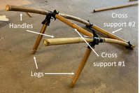
Figure 2. Handle/Leg Frame. Source: Tom Bierma
Step 2 – Handle/Leg Frame
The handle/leg frame is composed of two handles, two legs, and two cross supports (Figure 2).
2A. Handles
The two handles should be made from bamboo that is rigid enough to minimize flexing yet narrow enough to be comfortably grasped with the hand. Straight bamboo is acceptable, but a slight curve to the handles allows the wrists to be in a more neutral position when operating the wheelbarrow (note handle curve in Figure 2). The handles do not need to be the same length.
2B. Cross Support #1
The length of Cross Support #1 determines the width of the effective cargo area. For carrying standard 5-gal buckets, this width should be at least 66 cm (26 in). A greater width may be necessary if using a wide tire. However, the greater the width, the more difficult the wheelbarrow is to balance.
A fish mouth joint 1 is used to connect Cross Support #1 to the handles, so the length of the bamboo cut for this piece must take joint cuts into consideration. An original length of about 71 cm (28 in) can be expected.
Connect Cross Support #1 to the handles approximately 89 cm (35 in) from the front of the handles. This distance determines how far back the buckets can ride on the cargo platform as the lip of the buckets will contact the cross support.
2C. Cross Support #2
This also serves as the front support for the cargo platform. Cut a fish mouth joint in each handle to attach to Cross Support #2.
2D. Legs
Attach legs perpendicular to the handles using a fish mouth joint approximately 99 cm (39 in) from the front of the handles.
Step 3 – Cargo Platform
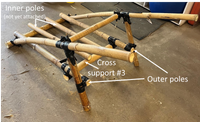
Figure 3. Cargo Platform attached to Handle/Leg Frame. Source: Tom Bierma
The Cargo Platform is built from one additional cross support and four platform poles that rest on Cross Supports #2 and #3. The two Outer Poles are longer than the two Inner Poles and connect to the legs (Figure 3).
3A. Outer Platform Poles
Determine the length of the Outer Platform Poles. Each pole rests on top of Cross Support #2, just inside from the handle, and is connected to a leg approximately 20 cm (8 in) from the bottom of the leg. The pole is attached with pegs, so it is critical that both ends of the pole terminate with a node for strength. An overall length of approximately 96.5 cm (38 in) can be expected.
3B. Cross Support #3
Attach to underside of Outer Platform Poles approximately 81.5 cm (32 in) from Cross Support #2.
3C. Inner Platform Poles
Cut poles but do not yet mount them.
Step 4 – Wheel Frame
The Wheel Frame supports the cargo platform and attaches to the wheel using two brackets. The Wheel Frame is composed of two brackets and two Wheel Frame Support Poles.
4A. Brackets
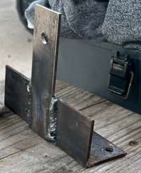
Figure 4. Bracket used to attach wheel to Wheel Frame Support Pole. Source: Tom Bierma
The brackets hang from the wheel axle and support the Wheel Frame Poles. There are many ways to connect the wheel to the Wheel Frame Poles, and the best method will depend on what is locally available and affordable. However, the connection must be sufficiently robust to support the cargo weight and various stresses during use.
The bracket we constructed is made from a piece of angle iron and a piece of flat stock, both 0.6 cm (1/8 in) thick (Figure 4). The angle iron is approximately 15 cm (6 in) long and 5 cm (2 in) wide, and the flat steel is approximately 4 cm (1.5 in) wide by 12.5 cm (5 in) long.
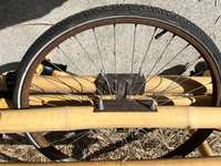
Figure 5. View of Wheel Frame with wheelbarrow upside down. Source: Tom Bierma
One hole is drilled near one end of the flat steel to accommodate the bicycle axle. Two holes are drilled in the angle iron to accommodate two bolts where the pole will rest (Figures 4 and 5). Weld the flat metal perpendicular to the angle iron. Attach the brackets to the wheel axle so that the brackets hang from the axle and the angle iron projects outward from the wheel.
4B. Wheel Frame Support Poles
Due to the weight supported by the Wheel Frame Support Poles, it is important that the poles have a node at each end. Center each pole lengthwise on a bracket and attach them with bolts.
4C. Attach Wheel Frame to Cargo Platform
Turn the wheelbarrow upside down. With the Wheel Frame also upside down, center the Wheel Frame on the Cargo Platform as best as possible. The goal is to center the axle lengthwise and widthwise while assuring that the wheel is parallel to the handles and perpendicular to the ground. Secure the Wheel Frame to the Cargo Platform with pegs. Keep the poles parallel when attaching.
4D. Attach Inner Platform Poles
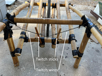
Figure 6. View of the twitch wires connecting the handles to the Wheel Frame Support Poles. Source: Tom Bierma
Turn wheelbarrow right side up and attach Inner Platform Poles to Cross Supports #2 and #3. Locate to provide a stable base for the buckets, yet avoid the joints where the Wheel Frame attaches to the Support Platform (Figure 6).
Step 5 – Twitch Wires
Twitch wires are added to directly connect the handles to the Wheel Frame. Without this, force applied to the handles to balance or steer the wheelbarrow must be transferred though several bamboo joints before reaching the Wheel Frame. The twitch wires also improve the rigidity of the wheelbarrow.
A twitch wire (also called a Spanish Windlass) is simply a loop of wire, string, or other suitable material that is tightened with a stick.2 We used paracord. A twitch wire can be easily re-tightened with additional twists.
Loop the wire over a handle behind Cross Support #1 and then around the Wheel Frame Support Pole furthest away from the handle. Add a stick and gently tighten until the wire is taut, but do not overtighten. Then do the same for the other handle so that the two twitch wires cross just above the Cargo Platform (Figure 6). Then alternate tightening each wire until rigid.
Step 6 – Shoulder Strap
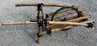
Figure 7. Shoulder strap attached to handles. Shoulder padding not shown. Source: Tom Bierma
A strap or rope over the shoulders and attached to the handles can make the weight much easier to bear (Figure 7). Padding should be used to transfer most of the weight to the shoulders and not the neck. We found that a properly placed rope allowed the wheelbarrow to be controlled with a minimal effort of the hands and arms, except on rough terrain or hills.
Tips for loading and transporting
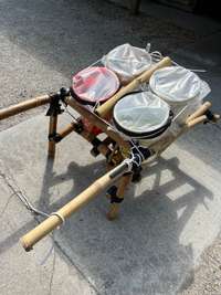
Figure 8. Spacing and securing 5-gallon buckets. Source: Tom Bierma
Though useful for carrying other things besides water, the wheelbarrow is designed to transport four 5-gallon (19 L) buckets of water (video link [http://edn.link/tn101video]). With the wheelbarrow resting on its legs, load the rear buckets first, then the front ones. We used a piece of bamboo above the wheel as a spacer to prevent the buckets from contacting the wheel (Figure 8). A rope was then placed around the outside of the bucket lips to keep them bound tightly together. This rope can also be tied to the handles or Cross Support #1 to keep the load from shifting on the platform, especially down hills.
The placement of the load on the platform can affect handling. Placing the load further forward reduces the weight transferred to the operator. However, it may add instability. Moving the load further back adds weight to the operator but enhances stability. With trial and error, each operator can find their ideal load placement.
When transporting water, the buckets should ideally have tight-fitting lids. However, in the absence of lids, we found that waste plastic film, secured with an inner tube or other suitable material, did a reasonably good job of preventing water from splashing out, with no more than 17 L (4.5 gallons) of water in the bucket.
We also found that a baffle in each bucket can be helpful. Without a baffle, water sloshes in each bucket in unison, requiring greater effort to maintain wheelbarrow balance. A piece of semi-rigid plastic wedged between the walls of the bucket significantly dampens the slosh (Figure 9). If each baffle is placed at a different angle, any residual sloshing is not in unison. The baffle material should be readily cleanable to avoid contaminating the drinking water.
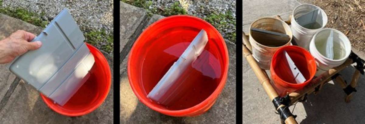
Figure 9. Semi-rigid plastic is used to make a baffle to reduce slosh. Each baffle is placed at a different angle. Source: Tom Bierma
Cite as:
Bierma, T. and E. Toevs. 2023. Bamboo Load-Centered Wheelbarrow. ECHO Technical Note No. 101.
References
The Chronicler’s Tale. 2020. The story of the Chinese wheelbarrow. YouTube. https://www.youtube.com/watch?v=0GlIPsDOP4U
De Decker, K. 2011. How to downsize a transport network: the Chinese wheelbarrow. Low-Tech Magazine https://solar.lowtechmagazine.com/2011/12/how-to-downsize-a-transport-network-the-chinese-wheelbarrow/
McCartney, L. 2020. Fence building end post twitch. Purdue Extension. https://www.youtube.com/watch?v=1ef2qPcLiLE
Osborn, R.A. and C.T. Woodbury. 1997. The Spanish windlass. Fine Homebuilding Issue 106. https://www.finehomebuilding.com/1997/01/01/the-spanish-windlass