Published By VITA 1600 Wilson Boulevard, Suite 500 Arlington, Virginia 22209 USA Tel: 703/276-1800 . Fax 703/243-1865 Internet: pr-info@vita.org
Understanding Ferrocement Construction ISBN: 0-86619-284-0 [C]1988, Volunteers in Technical Assistance
PREFACE
This paper is one of a series published by Volunteers in Technical assistance to provide an introduction to specific state-of-the-art technologies of interest to people in developing countries. The papers are intended to be used as guidelines to help people choose technologies that are suitable to their situations. They are not intended to provide construction or implementation details. People are urged to contact VITA or similar organizations for further information and technical assistance if they find that a particular technology seems to meet their needs.
The papers in the series were written, reviewed, and illustrated almost entirely by VITA Volunteer technical experts on a purely voluntary basis. Some 500 volunteers were involved in the production of the first 100 titles issued, contributing approximately 5,000 hours of their time. VITA staff included Patrice Matthews and Suzanne Brooks handling typesetting and layout, and Margaret as senior editor.
J.P. Hartog, the author of this paper, has worked over the past 30 years in naval architecture. Mr. Hartog is experienced in the areas of boat building and design, and has extensive knowledge of ferrocement design and construction. A native of Holland, he received his degree in structural engineering form the Technical University in Delft. He is presently employed by the Holland Marine Design, located in San Francisco, California.
Edward Harper, one of the reviewers of this paper, is a qualified boat builder with experience in wood, fiberglass, and ferrocement. He also lectures in naval architecture and ship building. He is employed by he College of Fisheries, St. John's, New Foundland. The other reviewer, Louis Zapata, operates Expressions, Inc., located in Washington, D.C. Expressions is an association of independent contractors doing rehab and add-on new construction. He received his B.S. in Physics from San Jose State College, Jan Jose, California.
VITA is a private, nonprofit organizations that supports people working on technical problems in developing countries. VITA offers information and assistance aimed at helping individuals and groups to select and implement technologies appropriate to their situations. VITA maintains an international Inquiry Service, a specialized documentation center, and a computerized roster of volunteer technical consultants; manages long-term field projects; and publishes a variety of technical manuals and papers.
1. OVERVIEW
What is Ferrocement?
Ferrocement is a building material composed of a relatively thin layer of concrete, covering such reinforcing material as steel wire mesh. Because the building techniques are simple enough to be done by unskilled labor, ferrocement is an attractive construction method in areas where labor costs are low. Sand, cement, and water usually can be obtained locally, and the cost of the reinforcing material (steel rods, mesh, pipe, chicken wire, or expanded metal) can be kept to a minimum. There is no need for the complicated formwork of reinforced cement concrete (RCC) construction, or for the welding needed for steel construction. Virtually everything can be done by hand, and no expensive machinery is needed.
Here are some additional advantages of ferrocement construction. Ferrocement can be shaped in any form. It can be formed into sections less than 25 mm (1 inch) thick and assembled over a light framework. The material is very dense, but structures made from it are light in weight. It is also rot- and vermin-proof, impervious to worms and borers, and watertight.
Ferrocement is more versatile than RCC and can be formed into simple or compound curves. In contrast, RCC construction is cast in sections and needs extensive and very solid formwork to support the weight of the concrete.
In Third World countries, ferrocement is almost always economically competitive with steel, wood, or glass-fiber reinforced plastic (FRP) construction, because steel and FRP are expensive and wood is becoming more and more scarce. Because its use for construction requires locally available materials and a large supply of hand labor, local jobs can be created.
What are the disadvantages of ferrocement? Structures made of it can be punctured by forceful collision with pointed objects. Boat hulls used in deep water are subject to this danger unless expertly designed. Because of the danger that many lives may be lost at sea, hulls for deep water should be constructed under direct, expert supervision. If serious damage does occur, it may be difficult in some countries to locate a skilled repair shop.
In corrosive environments (for example, sea water) it is often observed that after several decades the reinforcing materials become corroded. However, this failure is almost always due to incomplete coverage of the metal by mortar during construction. Special care must be used to cover it completely if the mortar is porous or is applied by spraying.
It is nearly impossible to fasten objects to ferrocement with bolts or screws, because drills usually break against the lightly covered reinforcing material. Fastening with nails or by welding is not possible.
Although the ease of ferrocement construction encourages people to try it who have never built anything, the results of amateur effort can appear shoddy. It has been observed that visitors to a harbor can immediately identify the badly built boat hulls as ferrocement; the casual observer usually mistakes neat ferrocement hulls for another material. Such perceptions often discourage authorities from approving the use of ferrocement.
Some Applications
Ferrocement's features make it useful in a wide range of applications, including aqueducts, boats, buildings, bus shelters, bridge decks, concrete road repair, factory-built homes, food and water storage containers, irrigation structures, retaining walls, sculptures, and traffic-caution signboards. In its final cured stage, ferrocement is somewhat flexible and can be bent slightly without developing cracks. Ferrocement can be used in such compound-curved structures as domes, roofs, and ship hulls. Compound curvature adds to the strength, stiffness, and impact resistance of these structures, which can be built over a minimum of internal forms. Round or conical tanks, silos, and pontoons can also be constructed very satisfactorily with thin-walled ferrocement.
The least desirable designs for ferrocement construction are those that have large flat surfaces combined with angles of 90 degrees or less. However, non-bearing walls, partitions, dock floats and septic tanks, with or without internal or external stiffening, have been successfully constructed. Large, flat-bottomed barges can also be built with ferrocement in combination with precast RCC frames and girders.
History
The practice of mixing burnt lime with water to make cement can be traced to antiquity. The Romans were the first to use concrete as a construction material. They made a hard-setting concrete by adding crushed volcanic powder (pozzolan) to the mixture. In the nineteenth century, modern hydraulic (Portland) cements came into use. Portland cements set hard, and can withstand loads up to 420 kilograms per square centimeter.
In the 1840s, Joseph Louis Lambot of France began to put metal reinforcing inside concrete. The Chinese had long used cement in combination with bamboo-rod reinforcing for building boats. The use of ferrocement as a boat-building material was demonstrated by the Italian engineer and architect Pier Luigi Nervi in 1945, when his firm built the 150-metric ton motor sailer Irene. The hull was only 35 mm thick, and was reinforced with three layers of 6-mm (one-quarter inch) rods. Four layers of mesh were used on each side of the rods. The hull weighed five percent less than a comparable wooden hull, and the price (at that time) was 40 percent less. The Irene proved to be a seaworthy vessel, with very little maintenance, and survived two serious accidents that required only simple repairs.
By the early 1960s, ferrocement had gained wider acceptance as a construction material, especially in boat building. After 1970, production slowed because of the rising costs of materials and, especially, labor. Ferrocement construction, however, continues to offer unlimited possibilities for uses both on water and land in places where labor costs are low.
2. TECHNOLOGY
Ferrocement is a form of RCC made from mortar and layers of thinly spaced steel rods or wires. Layers behave together as a composite, in which the concrete absorbs most of the compression and the steel reinforcing absorbs the tensile and shear stresses (see Figure 1 and Table 1). Mortar is the term applied to the mixture
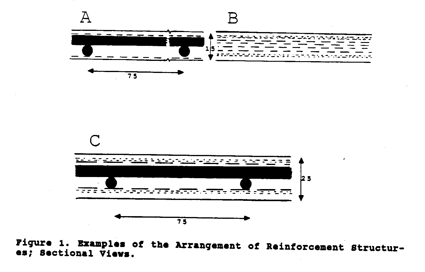
of cement, sand, and water before it solidifies into concrete.
The main steps in ferrocement construction are assembly of forms (if used), assembly of reinforcing materials, application of mortar, curing, and finishing and painting.
A. 5/8-inch (15-mm) slab. Two layers of 4.5-mm to 5-mm mild steel rods are spaced at 75-mm intervals horizontally and vertically. Two layers of 19 gage, 11-mm opening, square mesh on each side. Total weight, about 44 kg/m.sup.2, of which 18% is steel.
B. 5/8-inch slab. Four layers of expanded metal, 9-mm opening; one layer of gage 22, 12-mm opening, chicken wire on each side. Total weight, about 44 kg/[m.sup.2], of which 20% is steel.
C. 1-inch (25-mm) slab. Two layers of 6-mm (1/4-inch) mild steel rods spaced at 75-mm intervals horizontally and vertically. Each side covered with one layer of 19 gage, 11-mm opening, welded mesh. Then each side covered with two layers of 18 gage, 25-mm opening, chicken wire. Total weight, about 70 kg/[m.sup.2], (14.3 pounds/square foot) of which 18% is steel.
Table 1 FORCES ON FERROCEMENT STRUCTURES
Compression Tends to press together or make more compact.
Crushing Presses between two opposing forces so as to break, squeeze together, or put out of shape.
Flexing Bends or curves without breaking; perhaps under its own weight.
Impact Hits with force, collision, or violent contact.
Shear Forces two contacting layers to slide upon each other in opposite directions parallel to the plane of their contact.
Tension Tends to cause extension or increase in length.
2.1 FORMWORK
Forms can either be removable or can be incorporated into the finished product. They should be strong enough to support themselves and the weight of the steel and concrete structure before the mortar has set. Wooden frames are removable; if the work is done with care, they can be collapsed for reuse if more than one structure of a kind is to be made.
Wooden-Frame Method
Spaced, thin, narrow boards (battens) are nailed over fairly widely-spaced wooden transverse forms or frames. The first inside layers of mesh are positioned over the battens and tied or stapled to them. The other layers of mesh and rods are then solidly tied to the inside layers and to each other, and the entire form is checked for smoothness before applying mortar. After the structure has cured, it can be lifted off the form, which may be used again.
The advantage of the open wooden-frame method is that small structures can be built with simple woodworking hand tools. Disadvantages are that it requires a large quantity of wood, that it must be done carefully in order to get a good finish on the interior, and that the wood is some times difficult to remove and may not be reusable. This method is in common use for making small boats.
Pipe-Frame Method
Steel water pipe (schedule 40ST material, about 27 mm outside diameter, 21 mm inside diameter; nominal 3/4-inch diameter) takes the place of wooden frames. The pipes are incorporated into the ferrocement structure and act as transverse stiffeners. The longitudinal rods are positioned and tied to the pipes. The inner layers of mesh are tied to the rods and worked into position over the pipes.
For more complex structures, construction of the pipe frame can require welding and pipe-bending equipment (which can be as simple as two 35-mm diameter fixed pins in a solid mounting). Temporary reinforcing should be welded in because the pipe frames are very floppy. A disadvantage of the pipes is that unless filled with a thin mortar, they can rust out from the inside and leave a void.
Trussed-Frame or Webbed-Frame Method
Instead of pipes, trussed or webbed frames made of reinforced bars and rods can be used. The frames are covered with steel mesh. An advantage of this and the pipe-frame method is that adjoining parts of the structure can often be constructed together, saving time and effort and reducing the amount of wood framing needed.
2.2 REINFORCING MATERIALS
Many different kinds of reinforcing steel can be used. The material must be flexible; the tighter the curves of the structure, the more flexible the reinforcing material must be. Chicken wire may be the cheapest and easiest to use. It is adequate for most boats and for all uses on land, but is not recommended for such high performance structures as deep-water marine hulls. Wire mesh can be woven on site from coils of straight wire, using a hand loom adapted for the purpose.
For adequate crack-resistance, stiffness, and strength, a minimum of 30 pounds of steel to one cubic foot of ferrocement is recommended. This and other properties of ferrocement are shown in Table 2.
Table 2 SOME PROPERTIES OF A FLAT FERROCEMENT SLAB
Slab size = one square meter.
Note: 1 inch = 25 mm, 1 foot = 305 mm, 1 pound avoirdupois = 0.45 kg.
Minimal Minimal Thickness, Volume, Weight, recommended recommended mm [m.sup.3] kg Wt. of steel, reinforcing kg surface, [m.sup.3]
15 0.015 40 7 3 25 0.025 70 12 5 35 0.035 100 17 7
The adhesion between the mortar and the steel is of utmost importance in ferrocement construction. The specific reinforcing surface (the contact surface area of the rods, mesh, and/or expanded metal per unit volume of mortar) should be at least five square inches per cubic inch of mortar (Table 2).
Because the maximal tensile or shearing stresses (Table 1) occur at the surfaces of the ferrocement slab, the mesh layers should be positioned as close to the surface as possible. At the same time, the steel must be completely covered to protect it from corrosion (Figure 1). In thin-walled ferrocement , small-diameter
wires are used in the outer layers and the lowest possible cement-to-water ratio is used, in order to give the greatest protection against corrosion.
To prevent cracking, the mortar layer covering the mesh should be not more than 2 mm (3/32 inch) thick. Rods are used to space the mesh, hold it in place, and to give added stiffness and impact resistance after the mesh and rods have been tied together with wire ties.
If galvanized rods or mesh are used, a very small amount of chromium trioxide ([Cr.sub.2][O.sub.3]) should be added to the mortar water to prevent the formation of gas bubbles along the galvanized surfaces. The bubbles would adversely affect the bond between mortar and steel.
Instead of the conventional mesh-and-rods design, several layers of expanded metal have been used with considerable success. The layers of expanded metal are a little more difficult to form over compound curvatures, but they have sufficient adhesive surface, impact-resistance, and stiffness.
A minimum of two layers of 3/8 inch (9 mm opening) expanded metal, or equivalent weight in mesh or chicken wire, is used on each side.
Table 3 COMMON TYPES OF METALLIC MESH FOR REINFORCEMENT
Name Opening, Wire Weight, mm gage no. kg/[m.sup.2]
Galvanized, expanded metal 9 -- 1.85 Square, welded mesh 12 19 1.15 Stucco wire 25 20 0.49 Chicken wire 25 18 0.93 Chicken wire 12 22 0.62
Two layers of rods are used, usually spaced at intervals no greater than 100 mm both horizontally and vertically (Figure 1). For continuous strength, the mesh sections should be tied with a minimum overlap of 100 mm and the rods should have a minimum overlap of 40 times their diameter (a 250-mm overlap for 6-mm rods). Extra rods and mesh may be needed in certain areas; for example, at the stems and keels of boats.
2.3 APPLYING MORTAR
Mortar is made from a good grade of Portland cement, well-graded sharp sand, clean water and, optionally, small amounts of additives to achieve an earlier setting strength or for plasticizing. A rich mortar is used in ferrocement construction. The ratio of cement to sand should be 1:2 by weight.
The sand used in the mortar should be clean, dry, and sharp; 10% to 15% should pass through a #100 mesh sieve (opening 0.149 mm), and 100% through a #8 sieve (opening 2.38 mm). Only fresh water should be used for mixing. Although salt water does not affect the ultimate strength, it should be avoided, because it causes rust in the reinforcing. Up to 15% of the cement may be replaced by plasticizing and air-entraining agents, for example, pozzolan, diatomaceous earth, or fly ash. The ratio of water to cement should be 0.45:1 by weight if the sand is perfectly dry; otherwise it should be 0.40:1.
In some circumstances the use of a high-early strength Portland cement is advantageous, for example in production-line work, where it is desirable to remove the structures from the forms as soon as possible, or in cold climates to reduce the period needed for protection against low temperatures. Type III Portland cement, which is used primarily for mass production by commercial ferrocement builders, fulfills these requirements. However, its alkaline (salt-water) resistance is low. Type V Portland cement, although slower setting than Type III, is preferred for ferrocement construction because of its high resistance to sulfate and to alkaline solutions.
The chemical reaction between the cement and water (called hydration) in the mortar mix makes the mortar set hard. The hardening (and strengthening) of the mortar is rapid at first. It reaches near-maximum strength by the time curing is complete, usually up to 30 days. The mortar must be kept moist during application and curing.
The temperature during application and curing influences the ultimate strength of the structure. At freezing temperatures (0 [degrees]C) or below, growing ice crystals will destroy the bond between sand and cement, causing the structure to fail. Near the boiling point, the early hardening will occur too fast. The hydration process also produces some heat. However, in thin-walled ferrocement structures the heating effect is negligible. The mortar will generally achieve a compression strength of 4,400 pounds per square inch (310 kg/[cm.sup.2]) in 28 gays when the temperature is 15 [degrees]C (60 [degrees]F), in 23 days at 21 [degrees]C (70 [degrees]F), and in 18 days at 26 [degrees]C (80 [degrees]F).
It was stated earlier that for most ferrocement construction a water-cement ratio of 0.40:1 should be used for a workable mix and high strength. This ratio assumes that the sand in the mix is completely dry before the water is added. As this is hardly ever the case, allowance should be made for the water already contained in the sand; the volume or weight of the water to be added should then be adjusted. This can be done by taking two identical samples of the sand, weighing one sample on site, and drying the other one in an oven. The weight difference between the two samples shows the amount of water already in the mix. That weight should be subtracted from the amount of water to be added to the same volume of cement-sand mix as used in the sample.
The best test of a mortar mixture is to try it on a model section of the structure that is to be built. Use the same rods and mesh arrangement with the mortar that will be used in the structure. Another, less accurate, method is the widely-used "slump test". A sheet metal cone about 450 mm (18 inches) high is filled with several layers of mortar and rods. The last layer or mortar is trowelled flat and the cone is set base down on a flat, horizontal surface. Then the cone is carefully lifted, leaving the contents behind. The difference between the height of the metal cone and the height of the wet contents is called the slump; it measures the relative water content of the mortar. A good dry mix, as used for ferrocement, should show not more than 65 mm (2-1/2 inches) of slump. More would indicate excessive wetness and could result in shrinkage and cracks.
Compromises are sometimes necessary in the composition of ferrocement mortars. A high cement-to-sand ratio makes a strong, rich mortar, which is more workable, produces a better finish, and is far less permeable to water than a weaker mortar with a lower cement-to-sand ratio. However, a rich mixture shrinks more than a weaker mortar, causing hair cracks and sometimes large cracks as well.
For important projects, test panels should be made and, after curing, can be laboratory tested to determine crushing, compression, tensile, shear, and flexing strengths, as well as impact resistance (Table 1). In general, a mortar made with a cement-to-sand ratio of approximately 1:2 and a water-to-cement ratio of 0.40:1 will produce the least amount of shrinkage and a workable mix.
For large structures and where the distance from the mixing site to the construction site is considerable, it may be advantageous to pump the mortar to the construction area. A special plasterer's pump is used to transport the mortar through pipes to the work site. For better flow through the pipes, the water to cement ratio should be slightly higher than normal, with a slump of 75 mm or more. A disadvantage of this method is that incomplete mixing or separation of the cement and sand during travel can clog the pipes. They must then be taken apart, cleaned out, and reassembled, resulting in a substantial loss of time and labor. The available mortar guns have not been successfully used because the heavier parts of the cement-sand mix tend to separate at the hose nozzles.
After checking the reinforcing for smoothness (and pounding out flat spots, retying loose mesh, etc.), the structure is ready for mortar. All loose rust should be wire-brushed off; oily and dirty surfaces should be sprayed with a hydrochloric acid (HCl; danger: protect skin and eyes) solution and, after cleaning, neutralized with fresh water.
All the mortar should be applied at one time at an even temperature; it should be shaded from direct sunlight and winds, and protected from frost. A few simple tools are needed: buckets or shallow containers to carry the mortar; steel and wooden floats; soft brooms for erasing float marks; and long flexible boards for finishing long, curved surfaces.
The stiff mortar is pushed with hand pressure through the reinforcing. As this is done, great care must be taken to avoid leaving air pockets, which can occur in back of the rods or the expanded metal. In places where penetration is very difficult, a pencil vibrator or an orbital sander with a metal plate substituted for the sandpaper pad can be used to ensure complete covering of the reinforcing by the mortar. Localized vibration can also be created by using a piece of wood with a handle attached.
Air pockets can be located after curing by tapping the structure with a hammer. These places should be drilled out and filled with a cement and water grout, or an epoxy compound. Workers on one side of the structure push the mortar through the mesh and rods until it appears on the other side, where the other workers finish it off smoothly with approximately 2 mm of mortar protruding beyond the mesh. The same finishing is then done on the opposite side.
It is of the utmost importance that none of the work that has been completed be allowed to dry out while the workers are completing another part of the structure. In direct sunlight or during hot weather, moistened gunny sacks or other coarsely woven cloth should cover completed areas. If the work cannot be finished in one operation, the finished work should be kept moist, and a bond of thick cement grout or epoxy compound should be put on between the old and the new work. Several polyvinyl- acetate bonding products are also available. If a concrete mixer is available, a paddle-wheel type is greatly preferred over the conventional tilting-drum mixer, because of the stiffness of the mortar used for ferrocement construction.
2.4 CURING
Curing reduces shrinkage and increases strength and water tightness. There are two types of curing: wet curing and steam curing.
The ideal method of wet curing is to immerse the structure completely in water for a time that depends on the temperature of the water. However, immersion is not possible in most circumstances. The accepted alternative is to cover the structure, after all the mortar has been applied, with gunny sacks, tar paper, or other fabrics, which are kept moist continuously. Sprinklers or soaker hoses can also be used for this purpose. This procedure must be carried out for at least 14 days. It is desirable not to let the temperature fall below 68 [degrees]F (20 [degrees]C) during the curing process.
Steam curing provides a moist atmosphere as well as a higher temperature. It is necessary to build a polyethylene tent over the structure and move a steam-producing engine (a steam-cleaning plant or boiler) under this tent, close to (or under) the structure. No steam should be applied before the initial mortar set has taken place. After that, wet steam, at atmospheric pressure only, should be applied slowly for approximately three hours until the temperature inside the tent reaches 180 [degrees]F (82 [degrees]C). This temperature should be held for at least four hours, after which it can be allowed to fall slowly. The advantage of steam curing is that the mortar achieves its 28-day strength in 12 hours, and the structure can be moved and worked on within 24 hours, compared with a minimum 14 days for wet curing. However, steam curing may result in a less durable, more porous structure, especially if it is done by an inexperienced person.
2.5 FINISHING AND PAINTING
After curing, the surface is rubbed down with abrasive (carbide) stone to achieve a smooth finish, and then rinsed thoroughly with fresh water. Because well-made ferrocement is impermeable (waterproof), there should be no need for painting. However, if painting is desired, the structure should first be scrubbed with a 5% to 10% solution of hydrochloric acid (HCl; protect eyes and skin), flushed with clean, fresh water, and scrubbed again with a weak solution of caustic soda (NaOH; protect eyes and skin), after which it must be rinsed again.
The ferrocement can then be sealed with a coat of epoxy resin, and one or more coats of epoxy paint applied as a finish. In the author's experience, after sealing one side of the ferrocement slab it is best to wait as long as possible before sealing the other side. Due to continuous hydration and curing, the untreated surfaces will show a white powder for a long time. Even after careful removal of this powder and rinsing, it will take years before paint will form a good bond with the untreated surface.
If boats will be left continuously in salt water, an anti-fouling paint should be applied below the water line. For storage of diesel fuel in ferrocement tanks (not recommended because of the adverse effect of the alkaline action of the ferrocement upon the diesel fuel), the insides of the tanks should be sprayed with a polysulfide compound. Several kinds of epoxy resins and compounds are also available for the protection of bare metal, bonding cement to any other material, filling in voids, etc. Ferrocement tanks intended for water storage should be given a cement wash inside and stored with a little water inside them.
Underground ferrocement grain silos in Ethiopia are waterproofed with bitumen. After curing, the surface is cleaned with a wire brush, and a coat of bitumen emulsion (diluted 1 volume of emulsion to 1 volume of water) is scrubbed into the surface. After it dries, a cement-emulsion mixture (1 volume of water to 1 volume of cement to 10 volumes of emulsion) is brushed on.
2.6 EXAMPLES OF CONSTRUCTION FROM THAILAND
Example 1: Storage Silos
Food and water storage silos are constructed in Thailand using ferrocement with pipes or bamboo struts. The base of the cone-shaped silo is constructed first. Then mesh from the base is worked into the water pipe- or bamboo-framed walls. Hoops of reinforcing rod are positioned horizontally and are wired to the pipes. One layer of wire mesh is placed on the outside of the frame, and one on the inside. Mesh, rods, and pipe are then fastened together with short lengths of wire threaded through the wall and twisted with pliers.
The water tightness of ferrocement grain storage bins is tested by filling them with water for one week. Leaking indicates cracks or weak sections.
Example 2: Irrigation Channels
Ferrocement has been successfully used for farm irrigation and water-control structures, including water tanks, hydraulic gates, pipes, irrigation channels, and channel linings. Structures are thinner and lighter than RCC and can be prefabricated or built on site. The use of forms is optional. Typical drop channels measured 600 by 1000 mm. Thickness was 30 mm. Two layers of galvanized hexagonal mesh (gage 21 with 19-mm mesh opening) were used, one layer on each side of a framework of 6-mm mild steel rods, placed 250 mm apart both horizontally and vertically. The mesh was then tied to the rods with wire.
For a channel section, a mold of 2-mm mild steel was used. The mild steel rods were 5 mm in diameter, each side covered with one layer of galvanized hexagonal wire mesh, gage 21, 19-mm mesh opening. The edges of the mesh overlapped 100 mm. All fabricated structures were cured for 20 days. It was found that the channel sections could be made in larger units than RCC, thus reducing the number of joints.
3. SUMMARY
The advantages of ferrocement construction are as follows:
- It is highly versatile and can be formed into almost any shape for a wide range of uses;
- Its simple techniques require a minimum of skilled labor;
- The materials are relatively inexpensive, and can usually be obtained locally;
- Only a few simple hand tools are needed to build uncomplicated structures;
- Repairs are usually easy and inexpensive;
- No upkeep is necessary;
- Structures are rot-, insect-, and rat-proof, and non-flammable;
- Structures are highly waterproof, and give off no odors in a moist environment;
- Structures have unobstructed interior room; and
- Structures are strong and have good impact resistance.
The main disadvantage of ferrocement for smaller structures and boats is its high density (2400 kg/[m.sup.3], 150 pounds/cubic foot). Density is not a problem, however, for larger structures (for example, large domes, tanks, and boats over 12 m long). Large, internally-unsupported domes and curved roofs have been built that could not have been constructed with other materials without elaborate ribs, trusses, and tie rods.
The large amount of labor required for ferrocement construction is a disadvantage in countries where the cost of unskilled or semi-skilled labor is high. Tying the rods and mesh together is especially tedious and time consuming.
It is not possible to nail, screw, or weld to ferrocement.
BIBLIOGRAPHY
International Ferrocement Information Center, Proceedings of the Second International Symposium on Ferrocement, 14-16 January 1985, Bangkok, Thailand. Bangkok: author, 1985.
Journal of Ferrocement (quarterly). International Ferrocement Information Center, GPO Box 2754, Bangkok 10501, Thailand.
Narayan, J.P., V.V.N. Murty, and P. Nimityongskul, "Ferrocement Farm Irrigation Structures." Journal of Ferrocement, vol. 20, pages 11-22, 1990.
Paramasivam, P., and T.F. Fwa, "Ferrocement Overlay for Concrete Pavement Resurfacing." Journal of Ferrocement, vol. 20, pages 23-29, 1990.
Romualdi, James P. (ed.), Ferrocement: Applications in Developing Countries. Washington, D.C.: National Academy Press, 1973.