VITA 1600 Wilson Boulevard, Suite 500 Arlington, Virginia 22209 USA Tel: 703/276-1800 . Fax: 703/243-1865 Internet: pr-info@vita.org
Understanding Low-Cost Road Building ISBN: 0-86619-259-X [C]1986, Volunteers in Technical Assistance Revised 1990
PREFACE
This paper is one of a series published by Volunteers in Technical Assistance to provide an introudction to specific state-of-the-art technologies of intrest to people in developing countries. The papers are intended to be used as guidelines to help people chooe technologies that are suitable to their situations. They are not intended to provide construction or implementation details. People are urged to contact VITA or a similar organization for further information and technical assistance if they find that a particular technology seems to meet their needs.
The papers in the series were written, reviewed, and illustrated almost entirely by VITA Volunteer technical experts on a purely voluntary basis. Some 500 volunteers were involved in the production of the first 100 titles issued, contributing approximately 5,000 hours of their time. VITA staff included Patrice Matthews handling typesetting and layout, and Margaret Crouch as editor and project manager.
Joe Barcomb is a VITA Volunteer who is a civil engineer with the U.S. Forest Service. His co-author VITA Volunteer David K. Blythe, is a civil engineer and Associate Dean for Continuing Education for the Department of Engineering, University of Kentucky in Lexington. The reviewers are also VITA Volunteers. Jonathan Kibbee is a lawyer with Lord, Day and Lord in New York City who has worked in Haiti on a water control and development project. Henry W. parker, retired professor emeritus of civil engineering at Stanford University, has had extensive road construction experience in Colombia and Venezuela. Illustrations were done by VITA Volunteer Rick Jali.
VITA is a private, nonprofit organization that supports people working on technical problems in developing countries. VITA offers information and assistance aimed at helping individuals and groups to select and implement technologies appropriate to their situations. VITA maintains an international Inquiry Service, a specialized documentation center, and a computerized roster of volunteer technical consultants; manages long-term field projects; and published a variety of technical manuals and papers.
Roads vary from trails to major hard-surface highways. Depending on the local climate and materials available for construction, roads may sometimes be open to traffic for only part of the year. A year-round road is often more expensive to build, and may not always be necessary. As a general rule, road construction in rural areas can be done at relatively low cost because, compared to city roads, fewer people and vehicles travel on rural roads. However, rural roads must be well designed, properly constructed, and continually maintained.
I. QUESTIONS TO CONSIDER BEFORE BUILDING A ROAD
Before you begin to make decisions about designing, building, or improving a road or trail system, you should consider the following questions:
- Why do people want a road? Do they want to take produce or home industry products to market? Do they want access to medical assistance or other advanced technologies? Is a trail adequate to move people, goods, or animals, or is a full-scale road necessary? Whenever possible, try to get the local people involved in the design and construction of the road or trail. People will usually want to help build what they feel is needed, and people who have participated in the construction of roads or trails are likely to want to maintain them. If, on the other hand, you are not responsive to people's needs, they are not likely to provide you with much help.
- Where does the road need to go? Determine the route that best serves the users, getting them from their starting point to their major destination. If some intermediate points can be reached by going only slightly out of the way, then try to incorporate them also. Destination points are usually large villages or better transportation facilities.
- How much of the year is the road used and how heavily is it used? A road that is open year-round is often desirable but much more expensive to construct than one open only part of the year. Whether this extra cost is justified will depend in part on how much of the year the less expensive road would be unusable. For example, if a road crosses a riverbed that has water in it only three weeks out of the year, is it worthwhile to build a bridge? Generally speaking, the more traffic a road system carries, the more time and money may be spent on its construction.
- What kinds of goods need to be moved? Are they self-propelled (like trucks or cattle) or stationary (like bulk rice)? Are they small or bulky? You do not need the same type of road to transport jewelry as to transport grain. The jewelry could be carried by a mule on a seasonal trail, while the grain might require a road that was passable by truck under a variety of weather conditions. Animals can be herded along a trail or road, but logs might require a truck road.
- How do people currently travel and move their goods? Will there be a shift in the type of products coming from the outside world or from the local source? If not, then you should consider making limited improvements to the present road, for example, or a seasonal road into a year-round road. Improving a road or trail system significantly may not be warranted, especially if the local people do not have the vehicles or the operating skills to take advantage of a more highly engineered road.
- What kinds of vehicles are available to move people and goods? Are motorized vehicles used? If so, what size are they? If for example, motorbikes with a sidecar are the only vehicles used, a road with wide lanes is unnecessary. Buses and small trucks need a wider road than do animal-drawn carts. And an animal carrying a load on its back may not need a road at all.
- What is the physical terrain? Plan to use the terrain to your best advantage. Building roads on side slopes of 15 to 45 percent minimizes construction costs. Conversely, building roads on steep terrain usually means higher construction costs, because of the high volume of earth and rock that must be dug out and removed. Extremely flat ground also usually means higher construction costs, because measures must be taken to prevent floods and washouts. Rivers and streams should be avoided where possible since they may be costly to bridge. It is also wise to avoid other obstacles such as rock outcrops, ledges, highly erosive soils, and swampy places, since they are apt to create difficulties in construction.
- What technical skills are available? Are there personnel who have worked on similar projects in this or other areas who can form a cadre? Sources of external funding can often also make skilled technicians available.
- What equipment is available? Do you have power-driven equipment or are you limited to hand tools or animal-driven equipment? How might existing tools and methods be adapted to the construction process?
- What financing is available? Is there some form of local taxation that can raise the funds for building or improving the road system? If not, are funds available from other sources? How much money can be raised from all sources? Will the cumulative funds from all sources meet the needs of the project, or will the project have to be scaled down? Sometimes outside organizations will donate funds equal to the value of local donations of labor.
- What permissions will be required? Will you need written permission to cross land owned by other people, and will you need to secure any permits for public road access? You might need to get a right-of-way to change the course of a road, to widen it, or to block the flow of a stream. Such permissions should be obtained before construction begins, to avoid costly delays.
- How will the road system be maintained after it is completed? If local personnel are to maintain it, do they have a vested interest in doing so, or are they likely to let the road fall into such a state of disrepair that it will have to be rebuilt? Remember, if you build a system that does not meet people's needs, you can expect little commitment on their part to maintaining the system.
II. PLOTTING THE COURSE
Surveying
Before construction begins, the proposed road or trail location is plotted or sketched on paper. The next step is to walk the entire length of the proposed route to become familiar with the topography and ground conditions. The proposed route is then surveyed to measure its slope (also called its grade or gradient) at a number of points along its course. If the slope between the starting point of the survey and the next point along the course is too steep, the surveyor adjusts the route uphill or downhill until the desired grade is obtained. The two points are then tied in with markers. This process is repeated until the entire course is marked. The marked line represents the center line of the proposed road. Marking can be done with blazes (spots or marks made on trees), paint, strips of cloth, or weatherproof marking tape fastened to trees.
Allowances should be made for occasional turnouts to provide space for passing or parking vehicles. Any curves or switchbacks should be of sufficient radius to be negotiated easily by the largest vehicles likely to use the road. As construction progresses, a series of grade stakes or pegs are placed along the center line of the road. Two more or less parallel series of slope stakes or pegs are then placed to mark the sides of the road. See Section III, Tools and Equipment, for more information about maintaining grade and slope.
Measurment of Gradients
The steepness of a hill is usually expressed as the ratio between the height climbed and the horizontal distance covered. For example, you are climbing a hill and walk forward 100 meters. You find then that you are 10 meters higher than when you began moving. This means that for each 10 meters you have moved forward, you have also moved one meter upward. In that case, we say that the hill you are climbing has a slope of 1 in 10.
The main point that a road builder must always remember is that a roadway should not be built with a slope steeper than 1 in 10. Once in a great while, it may be necessary f or a road to be as steep as 1 in 7 f or a very few meters. This is an exceptional case, and a steeper gradient would make the entire road unusable. It is best never to accept a trace road plan showing a gradient greater that 1 in 10.
You can convert a gradient expressed in degrees into a gradient expressed as a proportion by using the following formula, in which 60 is a constant:
gradient as a proportion = 60 angle of gradient in degrees
For example, suppose that we have a gradient of 5[degrees]. We use the formula to find out how to express this gradient as a proportion:
gradient as a proportion = 60 5 = 12 gradient = 1 in 12
The same formula can be reversed to give us the gradient in degrees when we know the gradient as a proportion: 60 angle of gradient in degrees = ----------------------- gradient as a proportion
Remember that the gradient of a road should not be steeper than 1 in 10. That means that it should not be steeper than 6[degrees].
III. TOOLS AND EQUIPMENT
Tools for Finding the Grade
Equipment for building low-cost roads can very simple. Bulldozers and other large machinery may be nice, but they are costly to operate and difficult to keep in repair without access to a skilled mechanic and expensive spare parts. It is important, however, that the basic equipment be used to maintain the proper grade and slope. The most basic of these tools can be built by a reasonably skilled carpenter.
The Grading Stick
A grading stick can be used to establish a gradient of not more than 1 in 10. A grading stick is about five feet long with 6-inch bracket attached to one end so that the stick is ten times as long as the bracket. The slope that runs from the end of the stick to the bottom of the bracket is a gradient of 1 in 10.
The grading stick is used for placing the grade stakes or pegs so that the gradient is not steeper than 1 in 10. The bracket of the grading stick is placed on the peg that is further down the slope; the end of the stick is placed on the peg that is further up. A spirit level is then laid on the grading stick. The peg can now be raised or lowered until the stick is level. When it is, you know that the gradient is exactly 1 in 10.
The Abney Level
The Abney level is a more complicated and accurate instrument than the grading stick for finding the steepness of a gradient. <see figure 1>
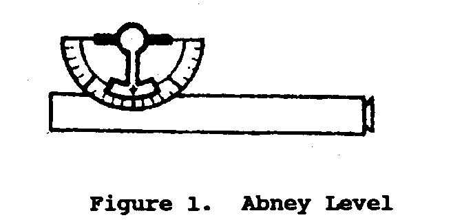
The Abney level is made up of three parts: (1) A tube about six inches long, with an eyepiece at one end and at the other end a thin wire that horizontally divides the opening; (2) An arm mounted above the tube, which can be moved along a scale calibrated in degrees; (3) A small spirit level, coupled to the arm. This level is reflected in a mirror set inside the tube. In the eyepiece you can see through the tube to the land beyond, which appears cut horizontally by the thin wire. You see the small mirror to the right of this. If you move the spirit level slowly, you can see the reflection of the level's bubble as it crosses the mirror.
The Abney level is best used along with a target and stick. The target consists of a piece of wood a foot square mounted at the top of a wooden upright about 4 feet high. The top half of the square is painted white and the bottom half black. The stick is an ordinary piece of timber cut so that its height is exactly the height of the point when the white half of the target adjoins the black half.
The level is placed on the stick. The target is taken to the place where the gradient needs to be determined. To use the level you look through the eyepiece and adjust the wire until it is exactly in line with the center of the target. You then move the spirit level until the bubble comes in line with the center of the target. The angle in degrees can then be read off the calibrated scale.
It is much quicker to use an Abney level than a grading stick to find a trace up a hillside, because with a grading stick, pegs have to be put in and checked at five-foot intervals. With the Abney level, the surveyor can walk along a likely trace and simply check, when the ground seems to be rising too steeply, that the slope is not greater than 1 in 10 (i.e., that the angle of incline is not greater than 6[degrees]).
Boning Rods
Boning rods are used to set the pegs that mark the center of the road, and ensure that the pegs lie in the same plane. The surface of a road or bush path built without the help of boning rods has many small dips and bumps, reflecting the shape of the ground under the road. Boning rods help assure that the surface of the road will be level. <see figure 2>
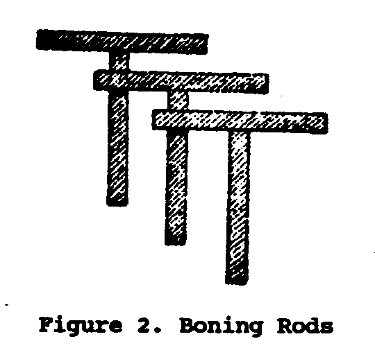
Boning rods are made of ordinary timber one inch thick. They always come in sets of three. All three boning rods in a set must be identical. For this reason, if one of the rods wears down or breaks, it must immediately be discarded and a new rod made to replace it. A boning rod is T-shaped; the height of the upright of the T is 48 inches, and the length of the crosspiece is 36 inches. The two arms are at right angles to each other, and must be fastened together securely with three screwnails. To use the boning rods, you put them on the first two pegs and then sight along the rods to place the third rod correctly. If the crosspiece of the third boning rod sticks up above the level of the nearer two, then you must drive the peg on which it stands further down. If, on the other hand, the third crosspiece cannot be seen, the peg is too low and must be made higher. When you have adjusted all three pegs in this manner, so that they are all in line, the person carrying each rod moves forward so that the next peg can be boned in (adjusted to the same level) in the same way the others were.
The overseer of a road-building project has to decide where the road will change levels. In flat country, it may be possible for the road to remain at the same level for distances of about 40 yards, but in hilly country the level may need to be adjusted as often as every five yards. Unless major obstacles like swamps and mountains are unavoidable, you will probably want to select a roadway that does not require adjustments in level of more than three feet. It is also desirable that the amount of earth that needs to be excavated (or cut) be the same as the amount of earth that needs to be used as fill.
Camber Rods
Camber rods are used to find the side to side slope, or camber, of the road. Like boning rods, camber rods are made of one-inch timber. They are usually eight feet long and have a bracket attached to one end of the rod, at a right angle to the rod. The bracket, which is attached to the rod by three screwnails, protrudes three inches below the rest of the rod. Camber rods are usually used in pairs, in conjunction with a spirit level. <see figure 3>

The pegs marking the center line of the road are "boned in" using the boning rods. Behind the crew that bones in these center pegs is a second crew that uses the camber rods to lay out the carriage-way of the road. The camber rod is put on the center peg, with the long rod at right angles to the center of the road, facing so that the bracket is on the outside. The bracket is then rested on a peg that will mark the edge of the roadway. That peg is driven into the ground until the spirit level shows the camber rod has become level.
The three essential things to remember are:
- The bracket always goes on the outside. (there is one
The three essential things to remember are:
- The bracket always goes on the outside. (there is one exception, which is explained on the next page.)
- The camber rod must always be at right angles to the center line of the road.
- The center peg must never be altered. Only the outside peg, or camber peg, may be adjusted to make the rod level. Once the camber peg on one side of the road has been adjusted, then the rod should be used to adjust the peg on the other side.
At this point, what you have is a line of pegs running down the center of the road and, parallel to this line of center pegs, two lines of camber pegs, one on either side of the road. The camber pegs are three inches lower than the center pegs, so that the sides of the road will be lower than the center. This slope is called the camber. It allows water to flow off the surface of the road into ditches running along the sides of the road. On a gravel or dirt road, a crown of 1/2 to 3/4 inch per foot (measured both ways from the center line) is adequate.
The camber pegs are joined with a string. Then the crew making the road can set to work. First, they need to cut and fill around the pegs. Then they tamp or level the ground by moving a board (or anything else with a straight edge) between the pegs. They dig a ditch on either side of the road, just outside the camber pegs. The slope of the sides of each ditch should be about 1:4 (1 meter of rise for every 4 meters of run), to prevent erosion. Earth removed in digging these ditches can be used to build up the camber.
The one exception to the rule that the bracket of the camber rod always goes on the camber peg occurs when a road curves so that its surface needs to be banked. If, for example, a road curves sharply to the left, a vehicle coming around the curve tends to skid toward the right-hand ditch. To help prevent this, the right-hand half of the carriageway is built up higher than its center. To bank the road in this manner, the camber rod is used in the normal way to set the camber on the inside (the left side in our example) of the curve. To set the opposite camber peg, the bracket is put on the center peg, with the flat end of the rod on the outside peg. The result is that the outside peg is higher than the center peg, and the center peg is in turn higher than the inside one. This is the only exception to the rule that the bracket always goes on the camber peg. And even in this exception, the bracket goes on the center peg only when the peg on the outside of the curve is being set.
MISCELLANEOUS EQUIPMENT
Several pieces of equipment should be mentioned in passing because they are so basic; hoes and machetes, headpans, wheelbarrows, and measuring tapes.
The Headpan
A headpan is a large pan, similar in shape to a dish pan. Workers carry it on their heads to transport earth or other loose materials. It has the advantage of being simple and durable, and usable even over rough terrain. When the terrain is smooth, a headpan is a relatively inefficient carrying device, since it takes about 40 headpans of sand or earth to make up a cubic yard.
The Wheelbarrow
Under most conditions, and especially over long distances, a wheelbarrow is a more efficient carrying device than a headpan because of its greater capacity. A wheelbarrow can hold about seven times what a headpan can, but does require some maintenance. The wheel axle needs to be oiled and the tire needs to be pumped to the proper pressure on a rubber-tired wheelbarrow. Without correct maintenance, the wheelbarrow is likely to break down.
The Measuring Tape
A measuring tape is made of flexible metal or of linen cloth, usually between 50 and 100 inches long. The linen is preferred to the metal because it costs less and lasts longer. It is necessary to clean and lightly oil the metal kind from time to time; otherwise it will rust.
IV. DRAINAGE AND SLOPE STABILIZATION
A very experienced engineer was once asked, "What are the most difficult problems encountered in road construction?" He answered, "Water, water, and water."
Heavy rains can trigger floods, washouts, and landslides. Smaller amounts of water can turn roads into puddles, ruts, and quagmires. Provisions must be made for adequate drainage if roads and trails are to remain in serviceable condition. In places where floods are an annual occurrence, it may be necessary to build bridges to keep the roads and trails usable year-round. In rainy areas and places with high ground water, ditches and road-shaping are needed to carry the water away from the road or trail surface. Too much water makes fine-grained soils soft and unable to support traffic. Too little water makes soils lose strength: dry fine-grained material is either blown away or pushed to the sides by traffic.
Where the slope is near zero percent, the best way to handle water is to build up the trail or road area with earth, so that it is higher than the surrounding area. In this case, every so often there needs to be a means for water to get from one side of the raised roadway to the other. Culverts, bridges, or fords can serve this purpose. A culvert is a conduit or pipe under a road or structure that permits the passage of traffic over water. A ford is a point where a road can cross a stream or river because there is little or no water there much of the year, and because the underlying soils can bear the weight of traffic.
A seep spring, or high water table will cause soft spots in a road. To solve this problem, you must remove the wet material and replace it with a suitable drainage structure. One way to do this is to remove the wet material and leave a trench sloping from the inside downward toward the outside of the road. Fill the trench with rock, starting with coarse rock at the bottom and progressing to fine rock as you move upward. The top of this filling should come to within a foot of the finished grade. Then cover this porous material with a suitable base material, well compacted.
On hilly or mountainous ground, the road or trail should have some grade built into its longitudinal axis. If the road has a ditch, the water collecting in the ditch will need to pass over or under the road. Water should not be allowed to run down a ditch or along the surface of a road or trail for any distance that allows the water to pick up speed. The steeper the grade, the faster the water travels. The faster the water travels, the more capacity it has to carry soil and erode the surface of the ditch or road. Water must be removed more frequently as the grade gets steeper.
CULVERTS
One of the most common methods of drainage is the installation of culverts. Culverts can be used to divert the flow of water in a natural stream, or they can be used to help control run off water that accumulates in the ditches. Culverts can be made of lumber, logs, concrete, steel, aluminum, or clay. You should be sure that the material you choose makes the culvert as durable and easy to install as possible, and that it will be able to support the loads that the road will be carrying. If a metal or concrete culvert is going to be carrying acid water, it should be lined with vitrified clay or asphalt.
Stream Culverts
If you can, install the culvert in the natural drainage channel and on the same grade as the stream. The inlet for a culvert should be at or below the level of the stream bed, not above it. Avoid filling under a culvert to bring it up to grade. Lay the culvert on solid ground and pack the earth firmly at least halfway up the side of the pipe so that water will not leak around it. The culvert needs adequate cover: a minimum of one foot, or half of the diameter of the culvert, whichever is greater. If it is not possible to cover the culvert adequately, then you should install two smaller culverts or a pipe arch. The cover needs to be compacted to keep the road from settling. If there is a problem with erosion at the inlet end of the culvert, then you need to install a headwall. It can be made of such materials as logs, concrete, or hand-placed riprap.
A culvert is usually made to run along a 2 to 4 percent grade so that it will not become clogged. You can use an Abney level to check the grade. The flow velocity of the water that runs through the culvert should be greater than 2.5 feet per second to prevent sedimentation but less than 8 feet per second to prevent scouring. Generally speaking, a 2 percent grade will give you water velocities within this range. The outlet end of the culvert should be at or below the toe of the fill, and there should be an apron of rock for the outflow to spill onto.
When there is no time to make an exact calculation, you can make a hasty estimate of the cross-sectional area needed for a culvert by doubling the channel area. This gives you just a rough approximation, since it does not take into account the shape, size, or slope of the area, or the surface vegetation, soil conditions, or rainfall intensity. YOu can make a more exact calculation of the cross-sectional area needed for a culvert by adding the widths of the ditch at the top (a) and at the bottom (b), and then multiplying them by its height (H):
(a+b) H
The result should be roughly equal to double the cross-sectional area of the channel.
Relief Culverts
There are two kinds of relief culverts: ditch-relief culverts and open-top culverts.
Ditch-relief Culverts. Ditch relief culverts are put in to move water under the road before it acquires enough volume and force to cause erosion to the ditch. The culverts should be spaced 200 to 300 feet apart on an 8 to 10 percent grade and about 500 feet apart on a 5-percent grade. There will be local variations in these figures depending on the width of the road, the type of soil, and the amount of rainfall. Ditch-relief culverts should cross the road at an angle of about 30 degrees (culvert outlet downgrade about half the road width) to provide good entrance conditions on steep slopes.
Open-top Culverts. Open-top culverts are used to remove water from the surface of the road. The initial cost is low, but this kind of culvert is hard to keep clean, must be installed and bedded with care, and may break up under heavy traffic. These culverts should be installed every 300-800 feet on roads with 2-5 percent grades and 200-300 feet where the grade is 6-10 percent.
DIPS AND WATER BARS
Dips and water bars are structures that help keep water from accumulating on the roadways.
As shown in Figure 4, dips--often called sags--are built at low
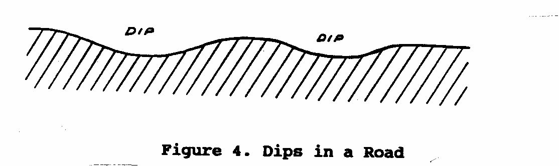
points in the road grade, where water seeks the lowest spot and runs off the road. Dips must be constructed with exactness: their length and depth must be adequate to provide drainage, yet not so excessive as to endanger traffic. Side drainage must be provided so that the dips do not become ponds that hold water on the roadway. Note that dips are not designed to handle constantly running water.
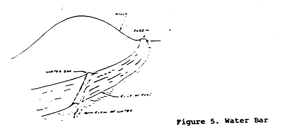
Water bars can be made of rocks, tree trunks, or compacted soil. (Soil is not normally used because it erodes too easily.) About two-thirds or three-fourths of the rock or tree trunk is buried in the ground, leaving 2 to 4 inches exposed above the surface. The water bar should lie at a 20 to 45 degree angle from the perpendicular of the road or trail. Water runs along the bar to its lowest point, where it runs off the side of the road. Figure 5 shows how a water bar redirects the flow of water.
DITCHES
There are two common kinds of ditches: trapezoidal ditches and v-shaped ditches. The trapezoidal ditch is more difficult to construct and maintain, but has a greater capacity than does a v-shaped ditch of the same depth. The minimum size of trapezoidal ditch that is practical to construct is 1-1/2 feet deep by 2 feet wide at the bottom. A special ditcher is required if a trapezoidal ditch is to be built by machine.
Whatever the soil type, heavy rain is likely to cause erosion in any ditch with a grade of over 4 percent. If the road is expected to be used for a short time only, the deepening of the ditch through erosion may not be a problem. But if the road is supposed to last, this erosion must be controlled, one way to do so is to line the ditch with stone or other riprap material. Any ditch with a grade of more than 10 percent should be paved.
Check dams may be put into the ditch at intervals to change a single rush of water into a series of gentle flows. Their height and spacing are chosen to produce the desired slope, usually one of below 4 percent.
The spillway of a check dam must have a definite weir or notch-type outlet. The bottom of the notch is the determining point for calculating the grade. The bottom and sides of the dam should extend 6 inches into the ditch line. The spillway needs to be protected with rock riprap. The side of the dam that faces upstream also needs to be protected from scouring. The check dam can be made of concrete, steel, rocks, logs, sandbags, or earth (earth should be used only if it is well protected from scouring).
TYPES OF ROAD SECTIONS
Five typical road sections and their uses are profiled below. Both steepness of the slope and the conditions of the terrain (e.g., whether the ground is dry or swampy) are factors that determine which of the sections must be built at any given point during road construction to permit good cross-drainage. For example, locations on the side of a hill permit good cross-drainage. They also have the advantage of involving a minimum of earth moving since what is excavated can be used as fill. When slopes exceed 60 to 70 percent in grade, this advantage is lost because the roadbed must be placed in solid material, so all of the excavated material becomes waste.
Turnpike Section. A turnpike section (Figure 6) is built on
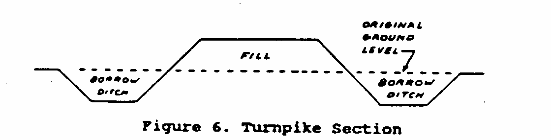
relatively flat ground with less than 10 percent slope, for example, in swampy areas. It is designed to raise the ground above the water table to prevent the road from being flooded. To make a turnpike section, earth is extracted, or "borrowed" from a ditch and used to create a fill on top of the original ground.
Fill Section. Fill Sections (Figure 7) are built on ground with
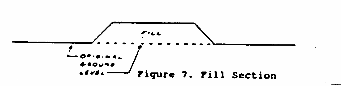
slopes of up to about 50 to 60 percent. Where slopes are greater than 60 percent, a fill section is used in drainage, raising the ground above the streambed to allow water to pass underneath the fill at ground level. To make a fill section, earth is taken from another section of road (or from another area altogether) and placed on top of the existing ground.
Through-cut Section. A through-cut section (Figure 8) is most
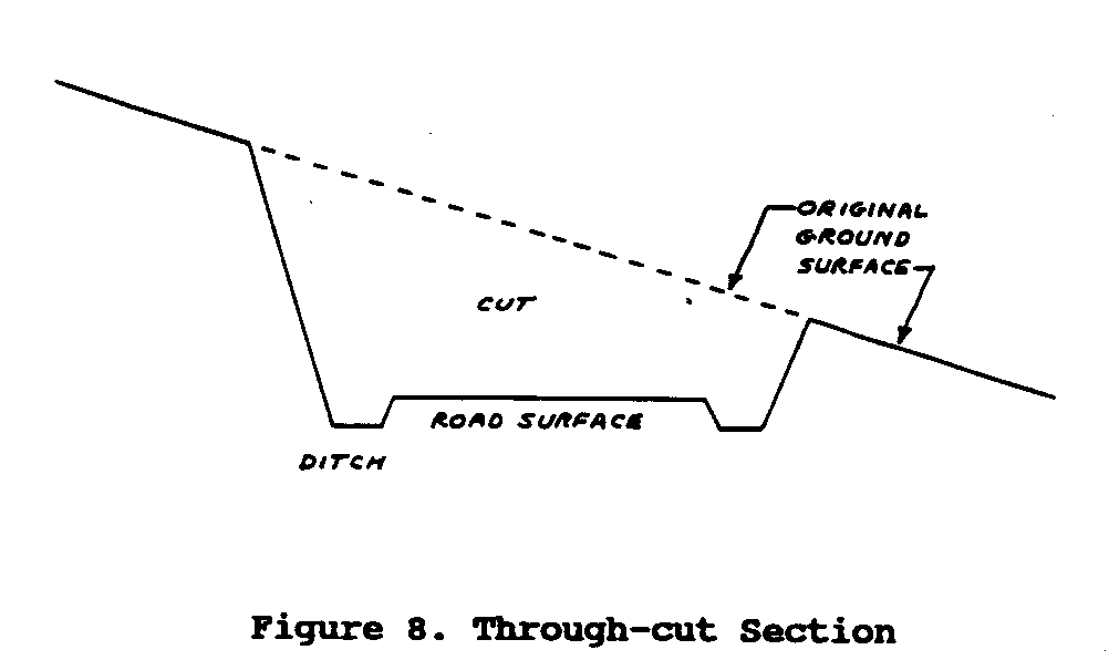
often used when the road or trail goes through a ridge that has a slope of less than 35 percent. This type of section involves cutting earth from the ground. This earth then needs either to be moved to another area where it will be used as fill or disposed of altogether.
Self-Balanced Section. A self-balanced section (Figure 9) is
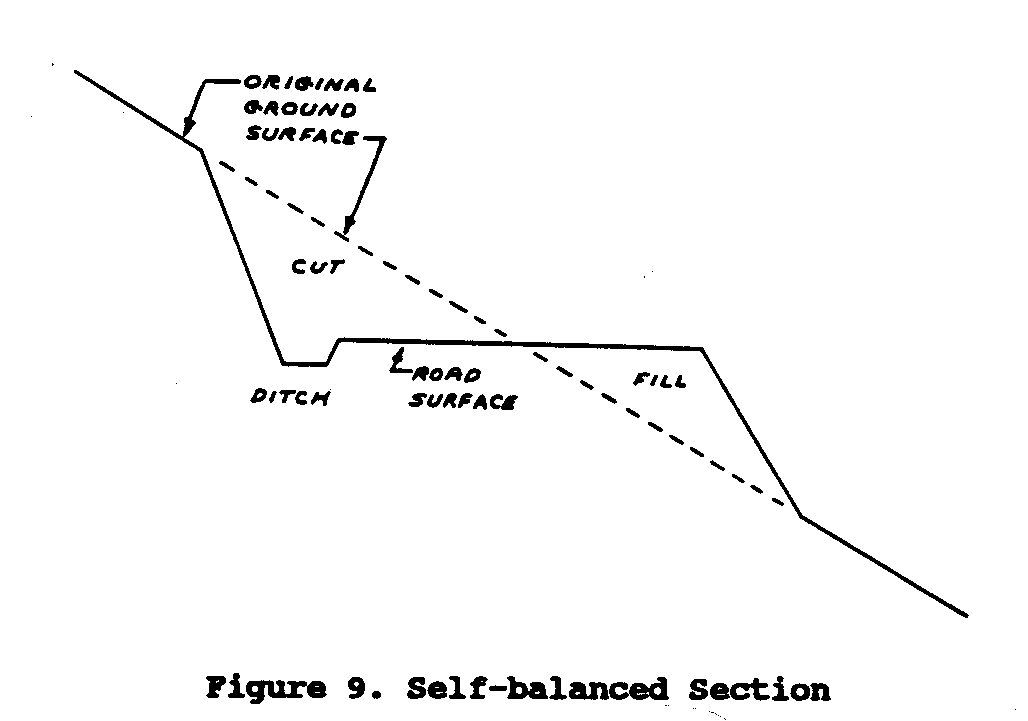
built on slopes of between 10 and 60 percent. Building a self-balanced section requires that the amount of earth cut out of the hillside be equal to the amount used to construct the fill portion of the road.
Full-bench Section. As shown in Figure 10, a full-bench section
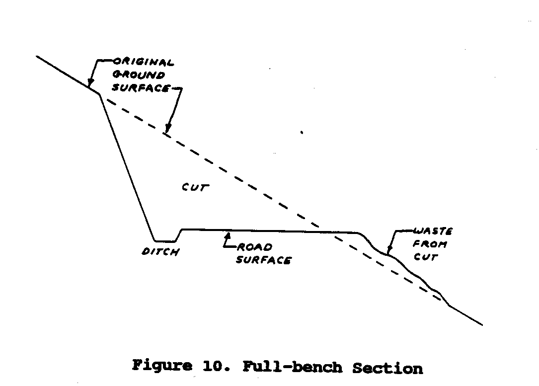
is built on slopes of 60 percent or greater. The term full-bench refers to the flat bottom that is produced when the ground is cut away to create the surface of the road. The material that is cut is either hauled off to an area needing fill, or it is disposed of over the roadside. Material that is disposed of over the edge of the road is not stable and is not meant to support traffic.
MATERIALS AND SURFACING
Soil and rock are the basic materials for constructing roads and trails. Sometimes all that needs to be done to make these materials usable is to remove the vegetation from their surface. It is also necessary to remove soil that is high in organic matter, since it cannot adequately support the weight of traffic. The rockier the soil is, the firmer the road will usually be and the more support it will be able to provide. But rocky soil has the disadvantage of making the surface of the road rougher. This can often be resolved by spreading a layer of rocky soil to provide support, and then covering the rocky layer with a 2- to 4-inch-thick layer of sand-clay mixture to provide a smooth surface. Usually, the soils are then shaped and compacted to provide for drainage.
Generally speaking, the road that you are building must have a surface that can both shed water and carry the expected loads. If you are constructing an all-weather road, you must find surfacing materials that will bear up under the full range of weather conditions. It is not always easy to find surfacing materials that meet these needs. Information on what materials are available in your area can be obtained from your local highway district.
Crushed stone, stream gravel, and tuff are among the many different materials that can be used for surfacing a road. The materials you choose should be tough and lasting. It is possible to upgrade a poor base material such as clay by mixing it with rock or stream gravel, and adding a stabilizing agent like calcium chloride or sodium chloride. You then compact the mixture to get a dense, dust-free surface. If the road is going to carry a large volume of heavy loads like lumber or coal, it may be economical to pave it with asphalt to avoid long periods of shutdown due to wet weather.
When the road is finished, short grass should be allowed to grow around the ditches. A carriageway of 12 feet only should be kept clear of grass. However, any culvert that crosses the road should be about twice as long as the road width so that there is room for two vehicles to pass each other at that point.
V. MAINTENANCE
Maintenance is required to keep roads and trails properly drained and fit for travel. Maintenance costs can be kept to a minimum in two ways: through good initial construction, and through proper, timely repair.
PERIODIC GRADING
Periodic grading of the road surface is necessary to fill in wheel ruts and to reshape the road. This is done with a motor- or tractor-drawn grader, a bulldozer, a rubber-tired skidder, or a road drag. (A road drag is a platform weighted down with stones and pulled behind a truck or tractor.
The purpose of grading is to restore the crown and to smooth the surface of the road. Be sure to maintain the slope of the crown 1/2 inch to 3/4 inch per foot, so that storm runoff can be shed. Shaping should be done at the end of the rainy season, after the heavy moisture is gone but before the road has become hard and dry. In the following months, routine smoothing should be done after a rain that has moistened the road but not made it slippery with mud.
DRAINAGE REPAIR
All ditches, culverts, water bars, and bridges must be kept clean and in good repair. Particular attention should be given to removing debris from culvert inlets, and to removing slides, rocks, and other materials that have slipped off the banks.
When routine maintenance of ditches is being done, it is important not to undercut the backslope. This will cause sloughing into the ditch, and bring about washout and bank erosion.
DUST CONTROL
Excessively dusty roads cause hazardous driving conditions, increase equipment maintenance costs, decrease the life of equipment, and deteriorate road surfaces through losses in surface material. Salts such as calcium chloride and sodium chloride are the least expensive and most effective materials for controlling dust. After shaping the road at the end of the rainy season, while the ground is still moist, apply one pound per square yard of road surface; during the dry season, apply one-half pound per square yard.
EROSION CONTROL
Roads not used for long periods must be protected from erosion. Drainage structures must be kept clean. Ditches and landings should be planted with grasses and other vegetation.
GLOSSARY OF TERMS
Bar (water bar) - A barrier placed in the road to divert water off the surface and over the edge.
Borrow - Soil or rock material removed (borrowed) from one area to be used in another area.
Cross slope - The slope of the terrain.
Culvert - A conduit under a road or trail to allow the passage of water.
Cut - The area excavated during construction of a road or trail.
Dip - A low point in a road or trail grade.
Ditch - A low point in the excavated portion of the cross-section, intended for water flow.
Fill - The area where excavated material is placed during construction.
Ford - A point in a stream or river where the water is shallow or nonexistant during much of the year, and where the underlying soils will support traffic.
Grade - The slope of the road or trail along its longitudinal axis.
Slope - The unit of vertical distance per unit of horizontal distance.
Waste - Excavated material that cannot be used in a stable fill.
BIBLIOGRAPHY
Armco Drainage and Metal Products. Handbook of Drainage and Construction Products. Middletown, Ohio: Armco, [date].
Booth, E.D., and Woolverton, D.N. CARE Manual of Feeder Road Construction. Freetown, Sierra Leone: CARE, 1977. This book assumes an engineer is available.
Dalton, J.C. Maintenance of County and Rural Roads. Engineering Experimental Bulletin 7. Moscow, Idaho: Idaho University, 1950.
de Veen, J.J. The Rural Access Roads Programme: Appropriate Technology in Kenya. Geneva, Switzerland: International Labour Office, 1980. Paperback.
Edmonds, G.A., and Howe, J.D.F.G. Roads and Resources: Appropriate Technology in Road construction in Developing Countries. London: Intermediate Technology Development Group, 1980. Paperback.
International Labour Office. Guide to Tools and Equipment for Labour-Based Road Construction. Geneva, Switzerland: International Labour Office, 1981. Paperback.
Jackson, Ian. Handbook of Fundamentals of Low-Cost Road Construction. Awgu, Nigeria: Community Development Training Center, 1955.
Weigle, Weldon K. Designing Coal-Haul Roads for Good Drainage. Berea, Kentucky: U.S. Forest Service, Experimental Station, 1960. This is an excellent reference for farm-to-market roads when no engineer is available.
SOURCES OF INFORMATION AND HELP
Most countries have a department of transportation or highways. Within the department there are often sections that deal with rural transportation and are good first contacts. If there is no such department, or if it does not seem willing to help, try similar departments in other countries where the same language is spoken.
It may be difficult to find people who are interested in assisting you on small self-help projects. Do not increase the project size just to obtain help. Remember what the users want.
American Association of State Highway and Transportation Officials 444 North Capitol Street, N.W. Suite 225 Washington, D.C. 20001 USA
American Society of Civil Engineers 345 East 47th Street New York, New York 10017 USA
Louis Berger International, Inc. 100 Halstead Street East Orange, New Jersey 07019 USA
Brazilian Road Research Institute Ipr/Dner Rod Pres. Dutra KM 163 Cep 21240 Rio de Janiero, Brazil
Brookings Institution 1775 Massachusetts Avenue, N.W. Washington, D.C. 20036 USA
Cornell University Local Roads Program 218 Riley-Robb Hall Ithaca, New York 14853 USA
Henry Grace & Partners Garthcliff, South Ridge St. George Hill Weybridge, Surrey ENGLAND KT130NF
International Road Federation 525 School Street, S.W. Washington, D.C. 20024 USA
National Association of County Engineers 326 Pike Road Ottumwa, Iowa 52501 USA
National Feeder Road Fund Federation Nacional de Cafeteros de Colombia Avenida Jimeng 7-65 Bogota, Colombia 281 8964
National Institute for Transportation and Road Research P.O. Box 395 Pretoria South Africa
ND LEA/Ministry of Public Works P.O. Box 152 KBYT Kebayoran Baru Jakarta, Selatan, INDONESIA
Royal Institute of Technology Department of Highway Engineering Brinellvagen 34, Stockholm S 100 44 SWEDEN
Secondary Road Engineering Federal Highway Administration 400 Seventh Street, S.W. Washington, D.C. USA
Transporation Engineering U.S.D.A. - Forest Service P.O. Box 2417 Washington, D.C. 20013 USA
Transportation Research Board 2101 Constitution Avenue, N.W. Washington, D.C. 20418 USA
U.K. Transport and Road Research Laboratory Crowthorne, Berkshire ENGLAND RGL 6AU
U.S. Forest Service Experimental Station Berea, Kentucky USA