Published by VITA 1600 Wilson Boulevard, Suite 500 Arlington, Virginia 22209 USA Tel: 703/276-1800 * Fax: 703/243-1865 Internet: pr-info@vita.org
ISBN 0-86619-062-7
[C] VITA, Inc. 1977
INTRODUCTION
VITA is pleased to make available the work of Jozef A. Kozlowski, who has contributed his expertise in the areas of water, wind and methane power generation to technical problems worldwide through VITA for almost 10 years. Kozlowski, who holds an advanced degree in engineering, specializes in onsite consultations and project work relating to solving problems in developing countries.
Jozef Kozlowski has built two Savonius rotors -- one in Wales and the other in rural Zambia. This manual details the construction of these machines. Both VITA and the author offer this manual with the hope that it first puts the rotors in a perspective which allows potential builders to judge the applicability of such machines for meeting their needs and then provides effective guidelines for constructing each.
The S-rotor, as it is more popularly known, is easy to construct. For this reason and others (not the least of which is that an S-rotor can be built for relatively small expense), people build rotors before they have investigated their own needs fully and/or have weighed these against the rotor's somewhat limited potential. The rotor will not meet all needs, and careful consideration of all factors and possibilities is essential for success.
For those who decide to build rotors, step-by-step construction details are provided. The manual includes a two-stage rotor for pumping water and a three-stage rotor designed to charge automobile batteries (the latter can be constructed using only hand tools). Both rotors depend upon use of discarded oil drums.
To provide additional information and guidance to the potential S-rotor builder, the author has reviewed a number of articles and books on the subject. The reviews, which are included as an appendix to this manual, are entirely an expression of the author's findings and opinions.
September, 1977
The Savonius rotor -- also called the S-rotor -- is a vertical-shaft wind machine invented by Sigurd J. Savonius of Finland some fifty years ago.
The rotor is relatively easy to construct, especially if made from standard 45 Imperial gallon (55 US gallon) oil drums which are generally available throughout the world, at a nominal cost for second-hand drums.
Because it rotates on a vertical shaft, the rotor can turn in wind coming from any direction and will start turning in very low winds.
<FIGURE 1>
A survey of available literature shows that the rotor is very suitable for manufacture in village and home situations and that it is not difficult to construct. However, the author feels the potential user should be aware of the fact that the Savonius rotor, when compared to other wind machines, may be less efficient and/or require higher wind speeds to achieve a power output more easily achieved by another type of wind machine.
The text on the following pages provides data compiled by various investigators on the amount of energy available from S-rotors at various wind speeds. The author feels the potential rotor builder should use these data carefully to see if an S-rotor can meet his needs--before he begins the construction process.
EXAMPLES OF POWER AVAILABLE FROM S-ROTORS
The following graphs provide specific figures on the power available from Savonius rotors.
Different rotors--reduced to the same size--are compared in graphs 1 and 2

and the accompanying tabulation. Graphs 3 and 4 show rotor output
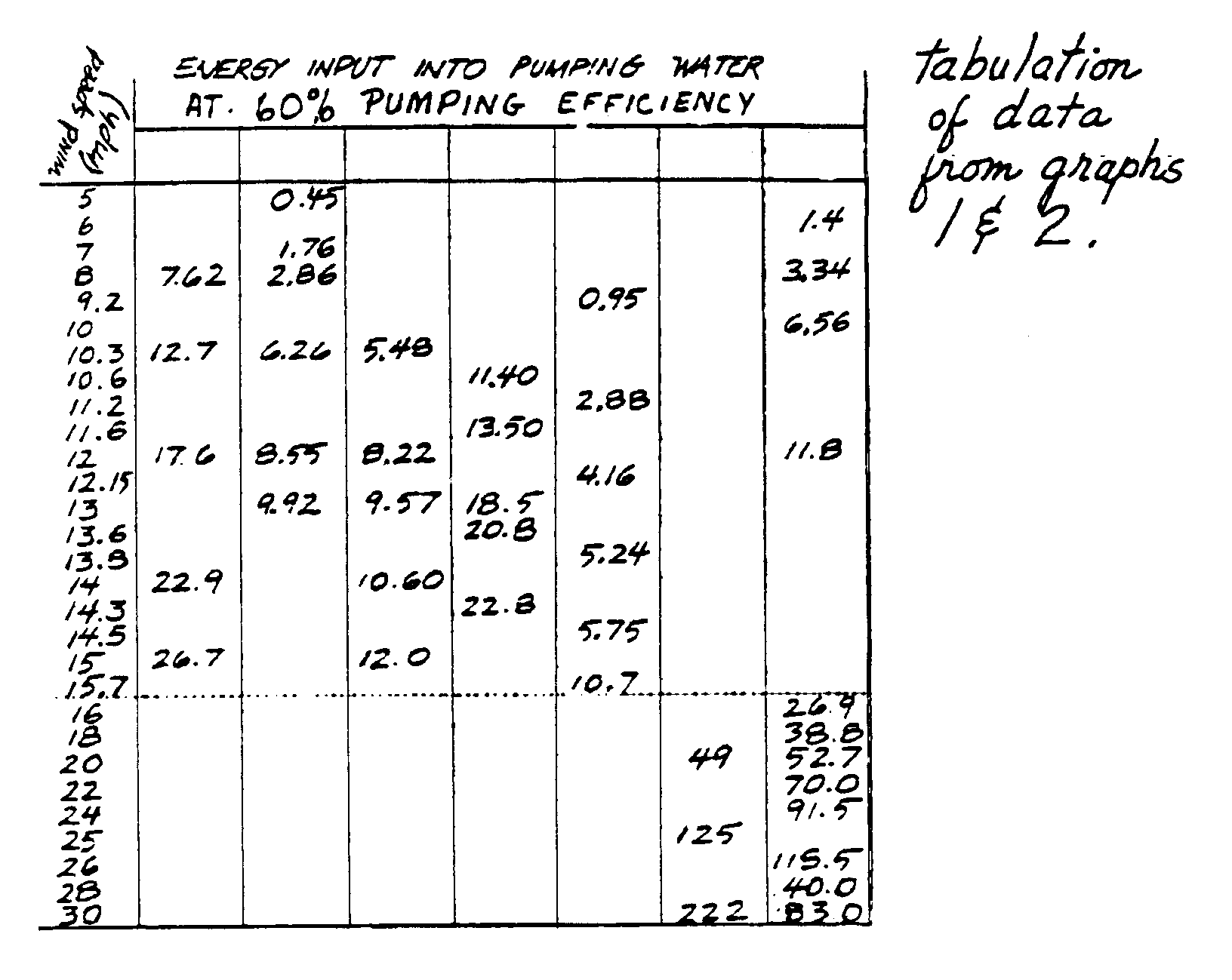

for a two-stage rotor and a rotor of 1m projected area respectively.
Here "input" figures measure energy available directly from the rotor. "Output" figures take into account losses based on the efficiencies of pumps or electrical transmission.
Note that in graphs 1, 2, and 4, the energy input figures are given in "watts per [meter.sup.2]." The calculation of area is based on the "windswept area," or the total area swept by the rotor, as you are looking straight at it from the side (as the wind would). Multiply the height of the rotor by the width at its widest point (the distance in a straight line between the outer tips of a pair of vanes).
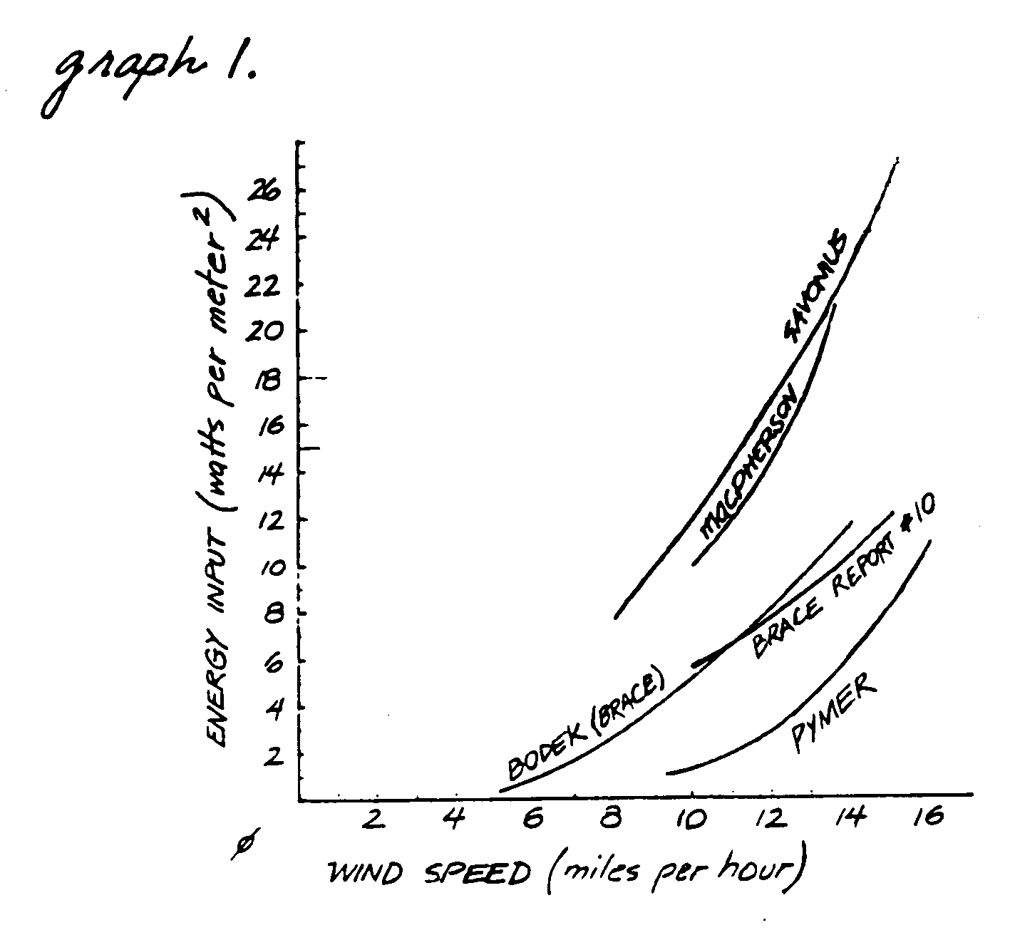
In graphs 1 and 2 the power per square meter of projected area of S-rotors is plotted against the wind speed, using test data from seven different sources. Although there are differences, all the results show that in wind speeds below 20mph the power generation is very small.
For example, the data from Bodek and Simmonds' experimental S-rotor in the West Indies shows that the useful energy from a 12mph wind imparted into pumped water is 8.5 watts/[m.sup.2]. This means that one can pump 75 Imperial gallons/hour up to 30' above the water level (341 liters/hour up to 9,14m). In an 8mph wind the useful energy is only 2.8 watts/[m.sup.2], which means that only 25 Imperial gallons/hour (104 liters/hour) can be pumped to the same height.
Note that for a 33 percent decrease in wind speed, the water output -- which is proportional to the power generated by the S-rotor -- dropped by approximately 66 percent. The power developed in a wind machine is proportional to the wind speed cubed. The significance of stronger winds is noticed immediately.
A 20mph wind will get the smallest commercial electrical generator working, producing about 100 watts of electricity. About a 30mph wind will be required for a car generator or alternator to start charging a 12-volt car battery.
It is up to the user to decide if it is worthwhile to build an S-rotor for winds of less than 20mph if stronger winds are rare in the area. Unlike horizontal-axis wind machines, S-rotors will begin turning in very low-speed winds -- but will produce only small amounts of usable power at those low speeds. It is not possible to give a precise formula for the power available at the generator or a pump because the friction and transmission losses are largely dependent on the design and accuracy of manufacture of the rotor. Since the rotor is intrinsically not very powerful, friction losses due to bad bearings and transmission losses could absorb most of the available power. Therefore, proper construction and excellent fitting of the bearings is most important. DETERMINE IF AN S-ROTOR IS SUITABLE FOR YOUR USE
It is very important to establish the following before attempting to build any wind machine:
Availability of wind. Find how often wind comes, its intensity, and its annual patterns. This information can generally be gotten from the nearest meteorological station. An alternative and more accurate method is to use an anemometer (wind speed measuring instrument) to measure wind speeds on a chosen site for a period of perhaps one year.
Intended Use of the Windmill.
- pumping water for household use
- generating electricity
- other applications
Choice of a suitable site. The choice of site will of course depend upon the intended use of the windmill. Then it is very important to select a location that will allow the windmill maximum exposure to wind, i.e., to get maximum power.
The top of a gently sloping hill with no trees, bushes or other obstructions to the wind is ideal.
However, if the windmill is to be used for pumping water, often the most likely place for a well is the bottom rather than the top of the hill, or even in the vicinity of buildings where the water will be used. If the site is sheltered from the prevailing winds by buildings, trees or other obstacles, it would be quite unsuitable for a windmill -- unless it is built on top of a tall tower or on top of a building itself. If this is the choice, then the windmill must clear the tallest obstacle by a minimum of about 10'(3m).
If the rotor is to be used for charging batteries, the top of a nearby hill, clear of obstructions, would seem to be a logical choice. Take into account that power will be lost when transmitted over a distance, and locate the rotor as close as possible to the place where the, power will be used.
At almost any site, the higher the windmill is mounted, the stronger the winds will be. The benefits of extra power should be compared against additional costs of a tower or a support structure.
CONSTRUCTION
The author has built two S-rotors. They are different in design and construction method.
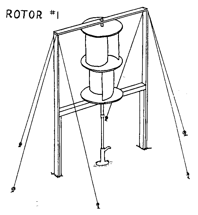
The first one, presented here as Rotor #1, is a two-stage rotor (two
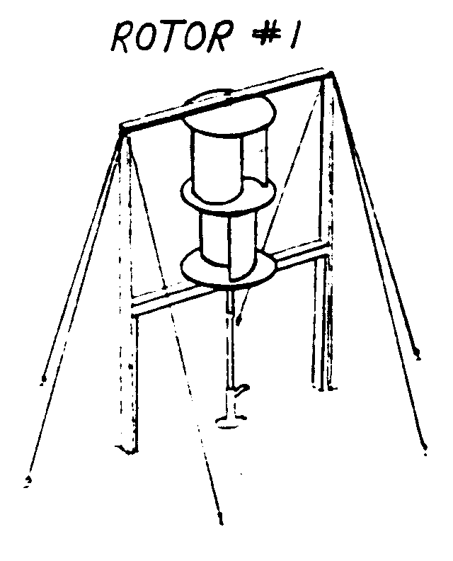
oil drums, each split in half and stacked vertically in pairs of half-drums) attached to a water pump. It can be duplicated easily where suitable materials and workshop facilities are available.
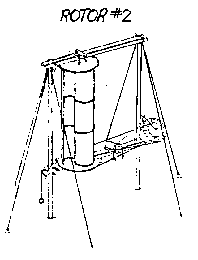
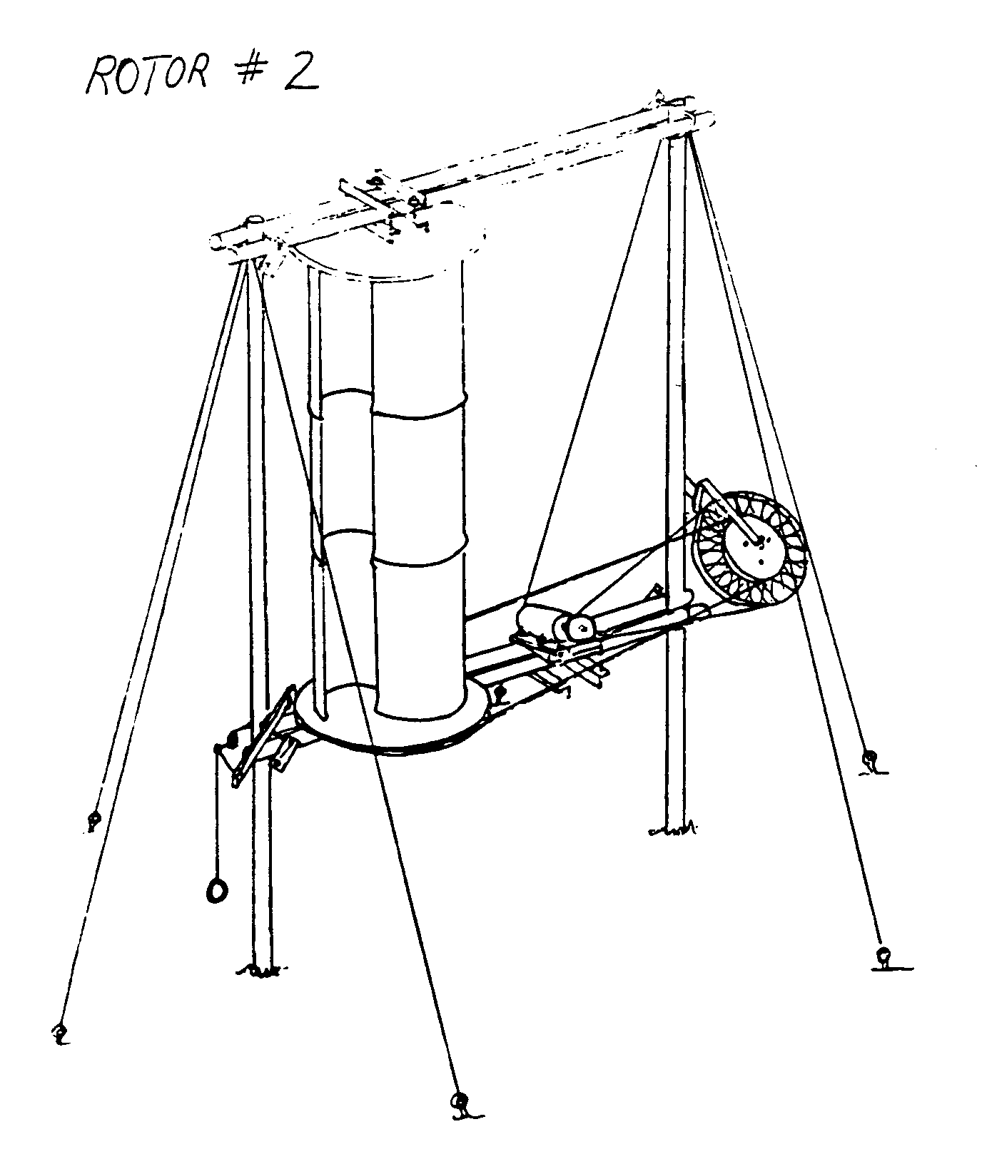
The second one, Rotor #2, is a three-stage rotor (three pairs of half-drums stacked vertically) designed for hook-up to small electric power generating equipment. Its method of construction would be appropriate in rural conditions with access to a village forge.
Access to a small machine shop, or something on that order, would be very helpful in the assembly of either of these rotors. Some sort of facility in which to form and cut mild steel will be required.
Both rotors use split oil drums for vanes. The drums are standard 45 Imperial gallon (55 US gallon) oil drums, which are available throughout most of the world; approximate dimensions of each drum are 34" (86cm) high x 20" (51cm) diameter.
A two-stage rotor, such as Rotor #1, which uses four half-drums, will produce approximately twice the power input of a one-stage rotor using two half-drums. A three-stage rotor such as Rotor #2, using six half-drums, will produce approximately three times the power input of a one-stage rotor.
A rotor having more than three stages would require design modifications, and would be difficult to build in rural conditions.
This is a two-stage S-rotor. A connecting shaft is attached to a positive-displacement rotary borehole (submersible) pump, manufactured by Mono Pumps (Engineering) Ltd. in England. Water is pushed up the borehole by a rotating screw-like mechanism. The vanes of the S-rotor are placed so the wind will turn the rotor in the same (counterclockwise--looking from the top) direction as that in which the Mono pump operates. Using a rotary pump of this type enables a direct rotor/ pump hook-up--with an extension piece connecting the S-rotor shaft to the shaft extending down the borehole to the pump. IF YOU USE A ROTARY PUMP MADE TO OPERATE IN A CLOCKWISE DIRECTION, MAKE SURE TO REVERSE THE DIRECTION OF ALL THE S-ROTOR, VANES FROM THAT SHOWN IN THESE PLANS.
VITA offers a number of technical bulletins containing plans for pumps. If you choose a pump that uses a reciprocating (back and forth) motion to lift the water, you will have to devise a mechanism to convert the rotary motion of the rotor to this kind of movement. Expect a certain loss in efficiency. Diaphragm pumps may be used if placed on the ground surface over a low head (that is, they cannot easily be rigged to operate down a borehole).
MATERIALS
* 2 standard 45 Imperial gallon (55 US gallon) oil drums
* One and a half 4x8' sheets of 1/2" thick plywood. 3 discs of 46" diameter will be cut from these. Marine quality plywood is best.
* About 45' of 2x4" wood, for rotor support frame. 2 pieces must have a continuous length of about 13' each.
* 1 wood beam, 4"x4"x6'
* About an 8' section of straight pipe (preferably steel), nominal (approximate) outside diameter of 1 1/4".
* About 1 sq. ft. of 1/4" thick flat mild steel sheet; about a 7" length of mild steel tube, with an inside diameter large enough to slide over the 1 1/4" pipe (above), and 1/4" wall thickness. These are to fabricate disc support brackets.
* 1 - 1 1/2' of solid steel bar, for shaft end pieces. See "MAKE SHAFT END PIECES" (page 21) for further considerations.
* 2 roller bearings, 1" minimum inside (shaft) diameter, with housings. The bottom bearing must be self-aligning in all directions. See "BEARINGS," page 18.
* Bolts. Nuts are not listed -- each bolt will take a nut of the appropriate size. Note: Bolt lengths are measured from the undersurface of the head to the tip.
* To fasten disc support brackets to discs: eighteen 3/8"x22"; thirty-six 3/8" look washers; eighteen 3/8" plain washers.
* To fasten disc support brackets to shaft: three 1/2"x3"; six 1/2" lock washers.
* To fasten drum brackets to discs: about sixty or seventy 1/4"x2"; twice as many 1/4" lock wasters.
* To fasten shaft and pieces to shaft: two 1/2" x 2 1/2"; four 1/2" lock washers; two 1/2" plain washers.
* Whatever number and sizes of bolts you need to fasten the particular bearings you select to the bearing support beams.
* About 10 large thick wood screws, 3 1/2" long, with good-sized threads, to fasten together rotor frame
* Cement, sand and water to make about 2 cubic feet of concrete for anchors
* A few feet of about 1" thick boards to make anchor mold
* About 8'-12' of 1/2" diameter steel rod, for anchor loops
* Strong wire or cable for guy wires. Length needed depends on number and arrangement of guys you use.
* Screw eyes or other strong connectors to fasten guy wires to rotor frame
TOOLS
* Hacksaw; you also may need a steel chisel (cold chisel), flame torch, or cutting electrode.
* Other hand tools--including screwdriver, hammer, saw, round file, wood rasp or sandpaper, metal rasp, nails (a few 3 1/2" ones), coping saw, pliers, wooden mallet, wood chisel, wrenches
* Drill--electric or hand, and a few different size bits, for wood and metal
* Level; measuring tape or rule; right-angle square
* Shovel
* Access to welding equipment to fabricate disc support brackets; access to forge to cut aid form mild steel
* Access to a metal lathe would enable you to form your own shaft end pieces; access to a milling machine would enable you to make a top bearing housing (although the author has made the bearing housing on a lathe alone)
* Tapping and threading tools to make connection between bottom shaft end piece and shaft extension pump
PREPARE HALF-DRUMS
Take off removable top and bottom lids from two 45 Imperial gallon (55 US gallon) steel oil drums. If lids are permanently fixed to the drums leave them on.
Cut the drums vertically into two equal halves. You can cut with a flame torch, electric cutting electrode, mechanically with a saw (quite difficult) or a steel chisel (cold chisel).
File away rough edges from all four half-drums. Beat out any disfiguration to shape with a wooden mallet.
<FIGURE 2>
PREPARE DRUM (ATTACHMENT) BRACKETS
Slot the top and bottom lips of each half-drum with a hacksaw. Slots should be approximately 1" (2 1/2 cm) apart. Small variations are not important.
Open up the curls with a large screwdriver.
Call these "drum brackets."
Drill 1/4" holes in every third or fourth drum bracket -- space the holes as evenly as possible. A hole must be drilled into the end bracket of each side of the half-drum, top and bottom.
<FIGURE 3>
Use a round file to remove the burrs and to open the holes slightly, if necessary, to accomodate 1/4" bolts.
MAKE THREE CIRCULAR WOOD DISCS
Draw three circles of 23" radius on 1/2" thick plywood marine quality is best). Drive a nail into the Plywood at the point which will be the center of each circle. Tie one end of a string to the nail and the other to a pencil--make sure the length of string between the nail and pencil measures 23". Keep the string tight and the pencil in a vertical position, and draw an accurate circle.
After drawing the circles, spot check the distance from the center of each circle to the edge in several places.
Cut out the three circles. Smooth the edge of each disc with a wood rasp and/or sandpaper.
<FIGURE 4>
On one side of each disc, draw a line from edge to edge through the center. This forms a diameter line.
On one of the discs draw a diameter line on the back side exactly at right angles to the line on the front side. This disc will be the middle of the three discs. Draw a 2" diameter circle and an 8" diameter circle around the center of each disc, on the marked sides (and on both sides of the middle disc).
Drill a hole in the center of each disc.
<FIGURE 5>
MAKE DISC SUPPORT BRACKETS
Make three disc support brackets by cutting, welding and drilling mild steel plate and tube.
These brackets will attach the plywood disc/half-drum assembly to a pipe shaft. Make sure each bracket slides over a chosen, straight 1 1/4" (nominal -- that is, will not be exact) diameter pipe at least 8' long. (Lead pipe out of question--too heavy and too soft.)
<FIGURE 6>
INSTALL THE DISC SUPPORT BRACKETS
Center a disc support bracket on the marked side of one of the wood discs. Trace its outside edge onto the disc.
Cut out the 2" diameter circle marked on the disc to form a hole in the center of the disc. Use a 2" hole cutter, or: drill holes all round the inside of the marked 2" circle with a small drill bit; cut the spaces in between the holes with a sharp chisel, tapping gently with a hammer; smooth out the hole with a wood rasp or file.
Hold the bracket firmly on the circle traced around its edge. Drill 3/8" holes into the wood through the six holes in the bracket.
Insert bolts and washers and tighten nuts to fasten the bracket to the disc.
Repeat the same procedure to attach the other two brackets to the other two wood discs. You may use either side of the middle disc for this purpose -- in assembly the bracket will be underneath the middle disc.
<FIGURE 7>
PREPARE HALF-DRUMS AND DISCS FOR ASSEMBLY As you go through the following preparations, mark all discs and half-drums so they can be reassembled later exactly as you have prepared them -- otherwise bolt holes will not align.
<FIGURE 8>

Place one of the two discs marked on only one side flat on the ground with the support bracket facing up. Mark this the bottom disc.
Place two half drums along the marked diameter line. The two tips A and B of each half-drum must be exactly on the line, and the inner tip A of each must also touch the circumference of the 8" circle drawn on the disc.
<FIGURE 9>
While the half-drums are in this position drill 1/4" holes into the disc through each hole in the drum brackets, inserting 1/4" bolts and nuts, and lock washers (underneath the bolt head and the nut) as you go. Start with the outer tip B of a half-drum, go directly to the inner tip A, and then drill the holes in between -- this will stabilize the half-drum for most of the drilling.
<FIGURE 10>
Place the middle disc flat on the ground with the support bracket facing up (that is, the bottom of the disc facing up).
Invert the bottom disc with the two attached half drums onto it, so that the free ends of the half-drums line up along the marked diameter line the same way as on the bottom disc. The pattern will form a mirror image of the bottom disc.
Drill holes through the drilled drum brackets in both half-drum edges into the middle disc. If you bolt through some of the holes to assist in drilling, remove the bolts when you are finished.
Remove the bottom disc and half-drum assembly.
<FIGURE 11>
Flip the middle disc over on the ground. Place the two remaining half-drums in position along the diameter line. (They will be at right angles to the alignment on the other side of the disc.)
Drill holes through the drilled drum brackets in the half-drum edges into the disc, bolting through some of the holes as you go.
<FIGURE 12>
Place the top disc flat on the ground with the support bracket facing up (that is, the bottom of the disc facing up).
Invert the middle disc with the two attached half-drums onto it, so that the free ends of the half-drums line up along the marked diameter line.
Drill holes through the drilled drum brackets in the half-drum edges into the top disc.
Take apart any discs and half-drums that remain together and set aside for final assembly later.
While handling the half-drums they may change shape slightly, causing bolt holes to move out of alignment with holes drilled in the discs. They may be brought into exact Shape when bolting up by exerting hand pressure.
BEARINGS
End pieces of the top and bottom of the rotor shaft each rest in a roller or ball bearing attached to a horizontal support beam. This insures smooth and efficient rotation. It is important to select good bearings and install them properly.
The author recommends using bearings with a minimum inside -- or shaft -- diameter of 1". The bottom bearing must be self-aligning in all directions, and must be capable of taking the dead weight of the rotor, which -- depending on its construction -- should not exceed 200 lb.; that is, the bottom bearing must withstand both an axial thrust and side loads of 200 lb.
The author has used a Fafnir 1" bearing type RCJ P1 (bearing #GC1100KRRB5) for the bottom bearing.
These are two other roller bearings which will do the job, top or bottom:
* Seal Master MSFT-16 (or MSFT-16C with a moisture-proof seal); costs about US$12.00 (may be more now).
* Seal Master LFT-16 (or LFT-16C with a moisture-proof seal); costs about US$6.50 (may be more now).
Bearings which provide for periodic lubrication without requiring disassembly will ease the job of maintenance.
There may be many bearings that you can find ready to install or adapt to use in the rotor. Keep in mind the loads involved, especially for the bottom bearing. Good bearings, installed properly, are essential to the successful operation of the rotor.
<FIGURE 13>
If you have access to workshop facilities you can make a housing to fit snugly around a suitable ball or roller bearing for the top rotor bearing. On the opposite page are diagrams of the housing the author made to fit around a bearing with an outside diameter of 2.81".
<FIGURE 14>
PREPARE BEARING SUPPORT BEAMS
Cut a 6'4" length of 2x4" wood beam for the top bearing support beam. It will rest and be fastened over the ends of the two tall vertical rotor frame supports.
Cut a 6' length of a 4x4" wood beam for the bottom bearing support beam. It will fit and be fastened between the tall vertical rotor frame supports.
<FIGURE 15>
The bearings will fasten onto the topside of each beam, at the center point. Drill or cut a hole in the center of the 4" wide side of the top bearing support beam large enough so that the end of the rotor shaft may extend up through to the bearing and rotate freely, without touching. Drill or cut a hole in the center of the bottom bearing support beam large enough so that the shaft extending down to the pump from the bearing will be able to rotate freely.
Drill holes through the beams in the pattern and sizes that match the holes in the flanges on the particular bearings you are using. Take care that your bearings will be accurately centered on each support beam. Fasten the bearings to each beam with bolts, nuts and lock washers.
You may have to prepare the wood surface of the bearing support beams differently, with chisels, rasps and files, or use good-sized, sturdy shims, to accomodate bearings with housings of configurations other than a plain, flat under-surface. THE BEARING HOUSING MUST SEAT FIRMLY WHEN BOLTED.
MAKE SHAFT END PIECES
Solid steel end pieces fastened to the ends of the pipe shaft provide smooth surfaces to fit into the bearings.
Whether fashioned on a lathe or adapted to this application from already-fashioned materials, the end pieces must be of solid steel and -- especially important if the bearings you use are not equipped with set-screws to lock the shaft in place -- have a smooth cylindrical surface that makes an interference (tight) fit into each inner bearing surface.
If you fashion the pieces yourself, make the portion that slides into the pipe end the appropriate diameter to fit into the pipe (you may be able to file the inside surface of the pipe end somewhat). Incorporate into the shape of the bottom end piece a protruding collar, with an under-surface milled smooth and flat, that will rest on the lip of the bottom rotor bearing. A collar fashioned into the top end piece may provide a surer fit into the particular bearing you are using, or may not be necessary.
The bottom end piece must be long enough to protrude out of the bottom of the bearing. Drill out and tap the center of this end piece with a left-hand thread to match the thread on the extension of the shaft of the Mono pump, which rotates counter-clockwise (as viewed from the top).
If you have no access to a lathe, find steel bar with a diameter that will fit tightly into each bearing that you have chosen to use. Depending on the bearing sizes and the actual inside diameter of the pipe shaft you are using, either grind down or build up (with a sleeve) at least a 3 or 4" length of each end piece to fit snugly into the end of the pipe shaft. If the bottom bearing you are using does not have set-screws to lock the pipe shaft positively in place, use a locking collar -- that can be purchased with some bearings -- around the protruding shaft of the bottom end piece, to rest on top of the lip of the bottom bearing. A Seal Master MSFT16-T (or MSFT 16-TC with a moisture-proof seal) is sold with a locking collar -- for US$13.40 (may be more now). You can do without a collar on the top end piece; take care in final assembly to account in your measurements for a space between the lower lip of the top bearing and the unmilled end of the pipe shaft.
<FIGURE 16>
ATTACH THE BOTTOM END PIECE TO THE PIPE SHAFT
Trim the bottom end of the pipe shaft to remove any threads. If necessary, file the inside surfaces to accomodate the shaft end piece.
Push the pipe end of the bottom shaft end piece into the pipe until the collar rests on the pipe end. Mark 1" from the end of the pipe with a punch. Drill a 1/2" hole through the pipe and the end piece, and deburr it. Keeping the end piece in place, bolt through the hole with a 1/2" x 2 1/2" bolt and tighten down with nut and washers.
ASSEMBLE THE ROTOR
Seat the bottom end of the pipe shaft in the bearing on the 4x4" bottom bearing support beam.
Support the bottom beam about three feet off the ground, with the pipe shaft projecting out sideways from it.
Slide the bottom plywood disc over the top end of the shaft, with the disc support bracket facing the top end. Position the bottom face of the disc 2 1/2 - 3" away from the top side of the bearing.
Holding the bracket firmly, drill a hole large enough to accept a 1/2" diameter bolt through the hole in the bracket collar and the pipe, and back out through the other side of the bracket collar. (If necessary, undo the bolts holding the support bracket to the disc and remove the disc.) Insert a bolt through the bracket and pipe, and tighten with lock washers and nut. Bolt back the disc if you have removed it.
Bring one of the bottom half-drums into position against the bottom disc -- make sure to match the correct half-drum to the position on the disc according to the marking system you have set up. Fasten it firmly against the disc with bolts, nuts and lock washers.
Slide the middle disc over the top end of the shaft with the support bracket facing the bottom end of the Pipe shaft. Bolt it firmly to the top end of the bottom half-drum that is in place.
<FIGURE 17>
Drill a hole through the support bracket collar and pipe as before -- 1" away from the bracket flange, and large enough to accept a 1/2" diameter bolt. Insert a bolt and tighten with lock washers and nut.
Place the remaining bottom half-drum in its marked position between the two discs and bolt into place.
Fasten the top disc to the pipe shaft:
* fasten one of the top half-drums to the middle disc.
* slide on the top disc -- support bracket facing down -- and bolt to the top of the half-drum.
* drill and bolt the support bracket to the pipe shaft.
* bolt the remaining top half-drum into place.
Bolt any remaining un-bolted drum brackets to the discs.
Leave about 6" of pipe projecting beyond the top disc. Cut any remaining pipe off squarely, and remove any sharp edges.
File the inside of the pipe so the top shaft end piece makes a push fit with the pipe. With the end piece in place, drill a hole all the way through it and the pipe, about 1" away from the pipe end. Insert a 1/2" x 2 1/2" bolt and tighten with washers and nut.
Seat the top shaft end piece in the bearing on the 2x4" top bearing support beam. Support each end of the beam about three feet off the ground, just like the bottom beam.
BEARING MOVEMENTS
The rotor must rotate freely in the bearings, without resistance.
The pipe shaft should be at right angles to the plane of rotation of each bearing. The bearing support beams should be parallel to each other. If either of the bearings you use are adjustable with set-screws, and the rotor does not turn freely enough, loosen the bearing from the beam, adjust the screw, and then tighten the bearing back to the beam. Test the adjustment by giving the rotor a turn. Repeat as necessary until smooth movement is achieved. If there is no way to adjust the shaft placement in the bearings you use, you may have to make slight compensations in the placement of the bearing support beams relative to the pipe shaft.
Balance the rotor according to the procedure giver on page 39. Final adjustments should be made on the rotor in its final, vertical position.
NOTE: New bearings may be stiff until they are broken in a little. because of the (grease) packing. Turr the rotor a number of times to begin this process. Do not confuse tight movement with rough movement. BEGIN ERECTING THE ROTOR FRAME
You may assemble the frame and rotor on the ground and then erect into position; or proceed as follows.
Sink two tall 2x4" wood vertical frame supports into the ground so that their inside surfaces are 6' apart, and two shorter pieces of 2x4" wood right up next to the inside surface of each of the taller supports. All the supports should be firmly embedded in the ground.
The bottom of the rotor should be about waist high. Cut each of the tall vertical supports long enough to include the portion that will be in the ground, the distance from ground to waist, a distance equivalent to the height of the rotor itself (from the point where the top bearing meets the shaft to the point where the bottom bearing meets it), plus an extra foot or so.
The top ends of the shorter supports should be at least waist height; the bottom bearing support beam will rest on them. This beam should be perfectly horizontal, so make sure the ends of the short supports are aligned at the right heights. Nail them into the tall supports.
<FIGURE 18>
MAKE ANCHORS AND ATTACH GUY WIRES
You must provide some sort of anchors and guy wires to stabilize the rotor frame. Sturdiness and structural integrity are important not only to protect the machine in high winds, but also to insure minimum wear on the moving parts in ordinary winds.
Four or six of these concrete anchors will work well. If you substitute some other device, make sure it will hold firmly in the ground against strong pulls that may be exerted by the machine and frame in high winds.
Hot-form 1/2" thick steel rods to this shape. Start with about a 2' length for each piece.
<FIGURE 19>
Make a wood mold. Pour in a standard mix of cement, sand and water.
<FIGURE 20>
Push a formed steel rod into place in the wet concrete mix. Allow to set for 24 hours, in the shade. Tap the mold to lift it off the anchor.
<FIGURE 21>
Make the rest of the anchors. When all dry -- they are strongest after curing for a week -- bury them in the ground with the loop in the steel rod just above the ground surface. The anchors must be placed far enough away from the rotor frame so the guy wires can exert a good pull against movements in the structure -- but not so far away that the wires are too long and elastic.
Attach guy wires -- good, strong wire or cable -- to the anchor loops and to screw eyes (or some other type of strong connector) placed near the tops of the tall vertical frame supports (make sure to attach them below the point where the supports will be cut off to correctly position the top bearing support beam when the rotor is in place). Make them tight enough now to keep the rotor frame in position while installing the rotor, but not so tight that they pull the top ends of the tall vertical supports away from each other. Turnbuckles along the wires will help you adjust the wires for maximum tightness after installing the rotor into the frame.
FINAL ASSEMBLY
Remove the bottom bearing support beam, with bearing attached, from the rotor assembly. Place it horizontally between the tall vertical frame supports with the ends resting on the top ends of the shorter vertical supports. Hold in position and drill holes for large wood screws through the tall vertical supports and into each end of the beam. Screw the beam into place.
On the rotor assembly, measure the distance from the bottom surface of the collar on the bottom bearing end piece to the bottom surface of the top bearing support beam, which is in place on the pipe shaft. Add the thickness of the bottom bearing housing to this figure. Mark off the distance of this total measurement on each tall vertical frame support, starting upwards from the top surface of the bottom bearing support beam. Cut off the top of each vertical support squarely at this mark.
Remove the top support beam from the rotor assembly and place it over the free ends of the vertical supports, bearing on top. Hold or clamp in position and drill holes for large wood screws through it and down into the vertical supports. Do not split the wood. Remove the beam.
Raise the rotor into position. This is at least a two-man job. Push the bottom shaft end piece down into its bearing, tapping gently if necessary. While the rotor is being held up by hand, position the top beam. Slide the bearing down over the end piece on the end of the pipe shaft, tapping gently with a mallet or heavy piece of wood. Screw the ends of the beam down into the vertical supports.
If the bottom bearing support beam has been installed perfectly level, and the pipe shaft is vertical -- at right angles to the beam, and the bottom bearing is properly aligned in its housing, then the rotor should rotate smoothly in that bearing. If there is any roughness in the rotation of the shaft end piece in the top bearing, you may try to make further adjustments (in an adjustable bearing) in the alignment of this bearing. If that doesn't do the job (or the bearing is not adjustable), you can try inserting shims between one end or the other of the top beam and the top end of the vertical support until there is smooth movement of the shaft in the bearing.
It is very important that the rotor turn freely. The bearings, especially the bottom one, could be ruined, with consequent damage to the rotor and frame, if improper bearings and installation procedure cause uncontrollable stresses and strains as the machine turns continually in the wind.
Take your time and be as resourceful as you can in these final steps. It is possible that you may have to do something like the following:
* dismantle the rotor from the frame to make adjustments.
* plane down the wood surface of a beam under the bearing to adjust the bearing to the correct angular relationship to the rotor shaft.
* go to a better bearing than one you were hoping would work.
Whatever you do now to get the rotor running smoothly will be worth the trouble you are thereby going to avoid later.
You may find it easier to make the final assembly on the ground in a horizontal position and raise it up after assembly by means of ropes. At least half a dozen men are required for this final operation.
This is a three-stage rotor design that the author built in rural Zambia. By means of belts and a bicycle wheel pulley mechanism it is geared to drive an automobile alternator or generator, which generates electrical current that is stored in automobile batteries.
<ROTOR 2>
An understanding of the procedures followed in assembling Rotor #1
will help you in putting this rotor together. Specific references are frequently made here to steps in Rotor #1 assembly where the same procedures or other information apply, rather than repeat the same material; but even in other steps it may be helpful to read through the corresponding material given for Rotor #1.
MATERIALS
* 3 standard 45 Imperial gallon (55 US gallon) oil drums
* About 32' of 12" wide x 1" thick boards, to be used in 3 1/2 - 4 1/2" lengths, for rotor discs
* About 10' of steel angle for disc braces
* About 14' of flat steel strip for disc braces
* About 5' of 1/4" thick x 1 1/2" wide steel strip, for disc/shaft brackets
* About 2' of 1/8" thick x 1" wide steel strip, for lid/shaft brackets
* A 10' length of straight pipe, 1 1/4" nominal (that is, will not be exact) outside diameter.
* 1 - 1 1/2' of solid steel bar, for shaft end pieces. See "MAKE SHAFT END PIECES," page 21, Rotor #1 and page 38, Rotor #2 for further considerations.
* 2 roller or ball bearings, 1" minimum inside (shaft) diameter, with housings. The bottom bearing must be self-aligning in all directions. See "BEARINGS," page 18, Rotor #1.
* 6 straight, sturdy wood poles (4 - 8" diameter), for rotor frame: 2 poles approximately 17' long for vertical supports; 4 poles approximately 10' long for horizontal supports.
* About 10' of 1/2" diameter mild steel rod, for U-bolt frame brackets
* About 3' of 3/16" thick steel angle, for frame brackets
* Up to 12' of 3/16" thick steel angle for bearing mounts
* Cement, sand and water to make about 4 cubic feet of concrete for anchors
* A few feet of about 1" thick boards to make anchor mold
* About 8' - 12' of 1/2" diameter steel rod, for anchor loops
* Strong wire or cable for guy wires. Length needed depends on number and arrangement of guys you use.
* Screw eyes or other strong connectors to fasten guy wires to rotor frame
* An assortment of bolts, nuts or other small, heavy objects to balance the rotor
* BOLTS. Nuts are not listed -- each bolt will take a nut of the appropriate size. Note: Bolt lengths are measured from the undersurface of the head to the tip.
* To fasten drum brackets to wood discs and to each other: about sixty or seventy 1/4" x 2"; twice as many 1/4" lock washers.
* To fasten braces to wood discs: about fifty or sixty 1/4" x 2 - 2 1/2", and twice as many lock washers.
* To fasten disc/shaft brackets to pipe shaft: four 1/2" x 2 1/2"; eight 1/2" lock washers.
* To fasten disc/shaft brackets to wood discs: sixteen 1/2" x 2 1/2"; thirty-two 1/2" lock washers.
* To fasten lid/shaft brackets to pipe shaft: two 1/2" x 2 1/2"; four 1/2" lock washers.
* To fasten lid/shaft brackets to half-drum lids: eight 1/2" x 2 1/2"; sixteen 1/2" lock washers.
* To fasten bearing mounts over bearing support poles: eight 1/2" x 5" - 7"; sixteen 1/2" lock washers.
* To fasten bearings to mounts: appropriate number and sizes, according to the particular bearings you use.
* sixteen 1/2" nuts for U-bolt frame brackets; eight 1/2" lock washers.
For accessory equipment:
* for rotor brake: 2-3' of 2" diameter wood pole; hinge and screws; small coil spring; a few feet of cord; small pieces of rubber.
* for transmission pulley and holder: bicycle wheel without tire; 1" thick board, 1 square foot; about 4' of 1/4" thick, 2" wide steel strip; a few bolts, nuts, washers, and wood screws.
* tire inner tube(s) to make transmission belts.
* up to 6' of 3/16" thick steel angle, appropriate numbers and sizes of bolts, nuts and lock washers -- to mount alternator or generator.
The following equipment must be compatible in operation -- as if from the same automobile or other similar system (author has used auto parts):
* alternator or generator
* voltage regulator
* storage battery or batteries
* suitable wire for hook-ups
TOOLS (the author used only handtools to construct this rotor)
* hacksaw; you also may need a steel chisel (cold chisel), can use a flame torch if available
* other hand tools -- including screwdriver, hammer saw, round file, wood rasp or sandpaper, metal rasp, wood chisel, small carving tool, wrenches
* drill -- electric works best --, and a few different size bits, for wood and metal
* level; measuring tape or rule; right-angle square
* access to a simple forge, or some facility to cut and form mild steel
* threading tool to thread 1/2" steel rod -- if you make metal rotor frame brackets
* shovel
You may have to find someone or some way to machine a cylindrical surface of the appropriate diameter onto steel bar, to fit into bearings.
MAKE WOOD DISCS
Make two wood discs. In this design there is only a disc at the top and a disc at the bottom of the rotor; there are no discs between the stages.
For each disc, lay four 12" wide boards (1" thick) side by side. Though the boards may be different lengths, they must be arranged so a 48" diameter circle can be traced on them.
Tack the boards for each disc together temporarily. Trace the circular outline of the discs onto each set of boards with a pencil on the end of a 24" length of string which is attached at the other end to a nail driven into a point marked as the center. Check the accuracy of the circle by measuring from the center to the edge in several places.
<FIGURE 22>
Fasten and brace the boards together with two parallel metal strips and small backup strips on opposite side each -- two angle-shapes toward the outside of the circle and two flat strips nearer the center.
Cut each disc to shape along the edge of the circle you have traced.
On the unbraced side of each disc, trace an 8" diameter circle around the center. Draw a diameter line on each disc, at right angles to the seams between the boards.
Cut a square with 2" sides at the center of each disc. Center the square as accurately as possible.
<FIGURE 23>
Prepare six half-drums from three standard 45 Imperial gallon (55 US gallon) oil drums. Take off any removable lids, and cut each drum vertically into two equal halves.
<FIGURE 24>
In the same way shown on page 11 in the instructions for Rotor #1, make drum brackets to fasten the half-drums to the wood discs, and to each other. Two stacks of three half-drums each will form this rotor. At about five (or more) points on each set of joining edges make the brackets line up evenly enough to drill a hole through each pair (see drawing below).
If the drums each had a removable lid at one end, you must also take care to plan that there will be a lid on a half-drum at each joining point between the stages of the rotor -- to provide a means of attachment to the rotor shaft.
The brackets on the half-drum edges that will fasten to the wood discs may be prepared without regard to alignment. As in Rotor #1, drill into every third or fourth bracket.
Mark each half-drum as you prepare it in this way, so you will know which ones belong together.
Drill all holes large enough to accept 1/4" bolts.
<FIGURE 25>
ASSEMBLE THE HALF-DRUMS AND DISCS
Place the appropriate edge of one of the half-drums that will fasten to a disc onto the marked side of the bottom disc (the one with the groove around the edge). Touch the two tips to the marked diameter line, and the inner tip to the circumference of the marked 8" diameter circle. Starting with the tips, drill through the holes in the drum brackets into the disc, bolting as you go with 1/4" diameter bolts, nuts and lock washers.
<FIGURE 26>
Repeat this procedure to fasten the other half-drum to this same disc, placing it opposite the first half-drum and aligning the tips in the same way.
Repeat this whole procedure to fasten the two appropriate half-drums to the top wood disc, MAKING SURE TO MIRROR THE CONFIGURATION ON THE BOTTOM DISC.
Complete the assembly of the drums and discs by bolting (or riveting if you wish) the remaining half-drums into place between the two disc/half-drum assemblies. Follow your marks on the half-drums to get the right joints together. Any changes in shape in the half-drums caused by handling can be overcome by hand pressure.
Cut a triangular-shaped notch with 2" sides into each half-drum lid between stages, centered 4" from the inside edge of each stack. These notches will fit around the pipe shaft.
<FIGURE 27>
PREPARE BRACKETS TO ATTACH DISCS AND HALF-DRUMS TO PIPE SHAFT
Prepare four disc/shaft brackets each of the following two sizes from steel strips (eight brackets altogether). These brackets will attach the wood discs to the pipe shaft.
<FIGURE 28>
Bend right angles into red hot steel. Drill holes to accept 1/2" bolts when the strips are cool.
<FIGURE 29>
Make four lid/shaft brackets of the following size from steel strips. These will attach lids of half-drums between rotor stages to the pipe shaft.
<FIGURE 30>
ASSEMBLE THE ROTOR
Select a 10' length of straight steel pipe with a 1 1/4" nominal (that is, will not be exact) outside diameter.
Push the pipe through the square hole in one of the wood discs, through the notches in the half-drum lids, and out the square hole in the wood disc at the other end of the rotor. Approximately equal lengths of the pipe should extend out from each end of the rotor (at least 6" on each end).
Fasten 4 disc/shaft brackets -- 2 of each size -- in a cross formation onto the outside surface of one of the wood discs, so that the 5" arms are on the disc and the shorter arms make opposite pairs up against the pipe shaft. The brackets with 2 1/2" vertical arms should be across from one another, and the brackets with 3 1/2" vertical arms should be across from one another. Place them first, mark the positions, and drill 1/2" diameter holes through the bracket holes into the wood disc and into the pipe shaft. Insert 1/2" x 2 1/2" bolts and tighten with nuts and lock washers. The 2 bolts through the pipe will form a cross, one above the other.
<FIGURE 31>
Repeat this procedure with the 4 remaining disc/shaft brackets on the wood disc and the pipe shaft at the opposite end of the rotor.
Fasten pairs of the smaller, lid/shaft brackets to the half-drum lids and the pipe shaft at each place where the lids are notched to let the pipe shaft pass through. Place them opposite each other, one on each half-drum lid. Use 1/2" x 2 1/2" bolts, nuts and lock washers.
<FIGURE 32>
BEARINGS
End pieces attached to the top and bottom ends of the rotor shaft each rest in a roller or ball bearing mounted on horizontal support poles. This insures smooth and efficient rotation. It is important to select good bearings and install them properly (good second hand bearings may be used).
Follow the same considerations given in "BEARINGS," page 18, Rotor #1.
MAKE SHAFT END PIECES
Solid steel end pieces fastened to the ends of the pipe shaft provide smooth surfaces to fit into the bearings.
See "MAKE SHAFT END PIECES," page 21, Rotor #1 for specific information. For this rotor, both shaft end pieces may be made the same - like the top end piece in Rotor #1. No extra length is needed on the bottom end piece to attach to a pump extension shaft.
ATTACH THE END PIECES TO THE PIPE SHAFT
Cut off each end of the pipe shaft squarely about 3" beyond the edges of the disc/shaft brackets -- if there is that much pipe; if not, simply make sure that the ends are trimmed squarely. If necessary, file the inside surfaces to accomodate each shaft end piece.
Push the pipe end of one of the end pieces into one end of the pipe until the collar rests on the end of the pipe. Mark 1" from the end of the pipe with a punch. Drill a 1/2" hole through the pipe and the end piece, and deburr it. Keeping the end piece in place, bolt through the hole with a 1/2" x 2 1/2" bolt and tighten down with nut and lock washers.
Repeat the sane procedure for the other end piece on the other end of the pipe shaft.
BALANCE THE ROTOR
Prepare two simple wood pole tripods. Place the top bearing in one and the bottom bearing in the other. Suspend the rotor horizontally between the tripods, with the shaft end pieces in the bearings. The bearings must be operating smoothly in order to detect any other causes of uneven movement in the rotor.
<FIGURE 33>
Give the rotor a few twists. If it tends to stop in the same position every time, then the side that comes to rest at bottom is the "heavy side." Tape one or more bolts close to the edge of the top side of each wood disc -- equal number on each disc. Spin the rotor again. Keep adjusting the number, size and position of the bolts until the rotor stops in any position.
Drill holes in the discs about 1 1/2" from the edge in the areas where the bolts were temporarily attached and insert them in the holes. If you drill the holes slightly Smaller than the outside diameter of the bolts, then the bolts may be turned in like screws. Otherwise fasten them with nuts and washers; if you do this then the nuts and washers must be used in the balancing process.
<FIGURE 34>
After the balancing bolts or equivalent weights are placed in position, spin the rotor again to make sure it is well balanced. If the rotor is poorly balanced it will shake apart at higher speeds.
THE ROTOR FRAME
The frame which will support the rotor is in the same basic configuration as the support frame for Rotor #1, with these differences:
* it is taller
* it is wider, to give room for a pulley and an alternator or generator mounting.
* it uses locally cut wood poles instead of boards that are cut at a sawmill.
* the horizontal supports (bearing supports) are in pairs -- notched and bracketed, lashed or otherwise fastened around the vertical supports.
Cut the straightest, strongest wood poles you can find (4"-8" diameter).
The frame is designed to combine strength and simplicity of construction.
Joints in the frame must be fastened together securely. One way is to make 4 frame brackets from 1/2" diameter mild steel rod. Bend suitable lengths to a U-shape while red hot. Thread the ends. Drill 2 holes in a section of steel angle to accomodate the ends of the U-bolt.
<FIGURE 35>
ANCHORS AND GUY WIRES
The rotor frame should be stabilized with at least 4 (preferably 6) guy wires running from the frame to anchors that are firmly embedded in the ground. See "MAKE ANCHORS AND ATTACH GUY WIRES," page 26, Rotor #1 for an anchor design and infortnation on guy wires. Do not attach guy wires now; the frame will be assembled to this rotor before it is raised into position.
BEGIN ASSEMBLING THE FRAME
It will be better to assemble the rotor and frame on the ground, and then raise into position -- since the whole structure is so tall.
The bottom of the rotor should be at least waist high; so cut the vertical support poles long enough to include: a 2' or 3' portion that will be in the ground; the distance from ground to waist; a distance equivalent to the height of the rotor (from pipe end to pipe end); plus an extra foot or so. (It should be remembered the higher you mount the rotor above ground the better.)
Lay the vertical supports about 8' apart, parallel to each other. Place a pair of 10' poles across from one to the other, so that they cross the vertical supports at points that will be about waist high, and at right angles to the vertical supports. These will be the bottom bearing supports.
Check for right angles, and mark the places where all the poles cross. Notch all the poles a little at these places. Fasten together, checking to maintain the right angles.
If you are using U-bolt brackets to fasten the poles, tighten the steel angle up against the wood with nuts and lock washers, and then tighten another nut up against each nut, for extra locking.
MAKE BEARING MOUNTS; INSTALL THE BOTTOM MOUNT AND BEARING
Each of the 2 bearing housings will bolt to the inside of steel angle assemblies that are bolted around the top and bottom bearing support poles.
Since the bottom bearing support poles are already installed, you can judge the lengths of steel angle-needed to cross over the top bearing support poles also. Cut 8 lengths of steel angle. Drill one 1/2" hole at each end of all 8 pieces. Position the holes so they will line up vertically with each other when the angle pieces are paired.
Work from the center point of each piece. Drill holes in the top two pieces of each bearing mount to accommodate the particular bearings you are going to use.
Install the bottorn mount onto the bearing support poles. Place it over towards one side, leaving enough room for the wood rotor disc to clear the vertical support. Center the mount across the poles. Bolt in place with nuts and lock washers.
Remove the bottom bearing from the end of the rotor on the tripod and install onto the mount with bolts, nuts and lock washers.
<FIGURE 36>
ASSEMBLE THE ROTOR AND FRAME
Remove the rotor frorn the tripods and lay it on the ground. Bring the portion of the rotor frame that is completed up around it. Push the bottom shaft end piece as far down as it will go into its bearing, which has just been mounted onto the support poles.
Assemble the top bearing mount and bearing loosely onto the top bearing support poles, in approximate position.
Bring the top bearing support poles into position, straddling the vertical supports. Slide (tap gently if necessary) the bearing over the top shaft end piece of the rotor as far as it will go.
Check these alignments:
* The rotor shaft should be parallel to the vertical support poles.
* The top bearing support poles should be parallel to the bottom bearing support poles.
* The plane of rotation of the top bearing should be perpendicular (at right angles) to the rotor shaft. This also applies to the bottom bearing.
Mark, and then notch, the top bearing support poles and the vertical supports where they cross. Fasten them together, maintaining all alignments. Tighten the top bearing to its mount and the mount to the support poles.
Support the frame horizontally, with the rotor in it, on temporary supports high enough off the ground so you can spin the rotor. The rotor must rotate freely in the bearings, without resistance.
Check all frame/rotor shaft/bearing mount alignments. You can make angular adjustments in the bearing mounts by inserting good-sized, sturdy shims. Loosen and retighten bolts and nuts as necessary.
If either of the bearings you use is adjustable with set-screws, you may further adjust for smooth movement. Loosen the bearing slightly from the mount to make these adjustments; then re-tighten.
NOTE: New bearings may be stiff until they are broken in a little, Because of the (grease) packing. Turn the rotor a number of times to begin this process. Do not confuse tight movement with rough movement.
Final adjustments may best be made when the rotor is in its final, vertical position.
INSTALL THE FRAME IN THE GROUND AND SUPPORT WITH GUY WIRES
Determine where you will place your anchors and bury them in the ground, with the connectors for the guy wires remaining above ground.
Attach screw eyes, or some other strong connectors, near the top of the rotor frame and fasten guy wires to them.
Dig two holes 2 or 3' deep, 8' apart. Raise the rotor and frame up vertically, placing the vertical supports into the holes. This is at least a six-man job. The bottom of the rotor itself should be at least waist high. Pack earth firmly around the vertical supports in the holes.
Pull guy wires tight through the connectors in the anchors, and fasten them. Turnbuckles installed along the wires will help you adjust the wires for maximum tightness.
Read through the last few paragraphs of "FINAL ASSEMBLY," Rotor #1 beginning with the last paragraph on page 27. The same basic considerations apply (excepting any planing of the beams).
CONSTRUCT AND INSTALL ACCESSORY EQUIPMENT
Rotor Brake
A hand-operated brake can slow or stop the rotor in high winds that might damage it. Attach a rubber-padded wood pole (of about 2" diameter) on a hinge to the vertical support next to the rotor, at the exact height of the wood edge of the bottom rotor disc (that is, not over the groove where the transmission belt will be). A spring keeps the brake lever away from the disc. Pull a cord (running through a guide attached to the vertical support) to bring the rubber-padded end of the lever against the rotor disc.
<FIGURE 37>
A positive lock can be made by drilling a hole near the edge of the bottom rotor disc to accommodate a 1/2" rod on a piece of cord. The rod would engage a hole in a small plate screwed to the bottom bearing support poles underneath the rotor disc.
Transmission Pulley
Make a pulley from a bicycle wheel (without tire) and a wood disc. Assemble them onto a "fork" and fasten the whole assembly onto the rotor frame with a bracket.
Cut a 10" diameter wood disc from a 1" thick board. Cut a rounded groove into its edge that is 1/2' wide and 1/2" deep. Drill a hole into the center of the disc to accept the end of the bicycle wheel axle. Drill 3 holes into the disc in a symmetrical arrangement around the center hole. Slip the disc over the bicycle wheel axle and bolt tight. Push bolts through the 3 holes, through the bicycle wheel spokes, and into small plates hooked behind the spokes -- tighten lock washers and nuts onto the bolt ends behind the small plates. The heads of these 3 bolts must be countersunk into the wood disc so they do not project above its surface -- to keep them out of the way of the large bracket, or "fork," that will hold the wheel and disc to the rotor frame.
Make a U-shaped "fork" out of 1/4" thick steel strip measuring 2" across. Start with a piece approximately 3' long.
Make a bracket from 1/4" thick steel strip, 2" across.
Fasten the pulley holder to the bicycle wheel axle. Bolt the small bracket to the pulley holder.
Whittle a groove into the rotor frame vertical support that is a few feet distant from the rotor. Make the groove on the outside of the pole, slightly above the bottom bearing support poles, and at a 15 - 25 [degree] angle to the horizontal.
Screw the bracket that is bolted to the pulley holder into the vertical support at this groove, with large wood screws.
<FIGURE 38>
A transnission belt can be made from an old automobile inner tube, provided the rubber is still elastic. An approximately 1" wide strip is cut "spirally" along the tube with a razor blade so that it is a continuous strip. Well over 100' of such strip can be cut from one inner tube. This is then twisted, and looped around the groove of the bottom rotor disc and the groove in the 10" wood disc that turns with the bicycle wheel. Tighten the belt, cut overlapping ends, tie a knot, and bury the knot in the twisted rubber. ALTERNATOR OR GENERATOR
Mount an automobile (or other similar) alternator or generator onto the bottom bearing support poles of the rotor frame, between the rotor and the vertical support with the transmission pulley on it. Use bolts, steel strips and steel angles to secure it, and a wood wedge to incline it at a 10-20 [degrees] angle.
<FIGURE 39>
Make another transmission belt and loop it around the bicycle wheel and the pulley on the alternator or generator.
ELECTRICAL CONNECTIONS
The wire connections and other electrical equipment such as voltage regulator should be similar to those in automobiles. Preferably suitable equipment from the same automobile should be used.
NOTE: As small as possible alternator/generator should be used as the more powerful machines will not turn in the lighter winds.
Two typical wiring diagrams are shown. Standard automobile parts might be used but must be compatible. That is, an appropriate voltage regulator to the alternator and the battery to be charged must be used. (Space limitation here does not allow elaboration on the generating equipment. Reference should be made to the literature on the subject or an experienced auto-mechanic should be consulted.) Both the alternator and the generator circuit should be in principal the same as those in the motor cars from which they were removed.
alternators or generators require fewer rpm's of the rotor to "cut in" and begin generating electricity.
<FIGURE 40>
APPENDIX
An Overview of Some S-Rotor Publications . . .
- The Wing Rotor in Theory and Practice, by Sigurd J. Savonius, Eng. Capt. Lt.N.R., published by Savonius & Co., Helsingfors, Finland, 1925, 39 pp.
Written by the inventor of the wind machine, this booklet describes principles of operation, construction of various models built by the inventor, and some test results on those models. A comparison is made with the performance of the rotor and some standard multi-blade windmills. The conclusions which Savonius drew from his tests seem to contradict the experience of all others: he claimed that his rotor was considerably more efficient than a multiblade windmill of the comparable swept surface area.
Since the details of Savonius' experiments are not given, it is impossible to say where he has erred. By comparing the curves on graph #1, it can be seen that his results are more optimistic than those obtained by others.

- How to Construct a Cheap Wind Machine for Pumping Water, Do-it-Yourself Leaflet #5, February 1965, by A. Bodek, published by Brace Institute.
This booklet presents a fairly single method of building an S-rotor from 45 (Imperial) gallon oil drums. The construction steps are somewhat sketchy and may not give enough detail for someone not familiar with construction procedures.
Alternative materials and construction methods should be specified for making the discs, or end plates, in conditions such as those prevailing in developing countries -- ordinary plywood is not always available or affordable; and marine quality is far better in this application anyway.
A design is given for transmitting a rotary motion into a reciprocating motion suitable for operating a piston or a diaphragm pump. But I think that the friction losses of the proposed system would be considerable. Also, the suggested diaphragm pump has several structural limitations: it is comparatively large in diameter and therefore quite unsuitable for a borehole; it must be secured at the bottom of the borehole against the pull of the connecting rod -- a very impractical proposition. The pump is not suitable for large heads of water; the 15' (5m) head suggested in the example has little practical application. Because the moving structure and the connecting rod are quite heavy, they will absorb a substantial portion of the available energy. It seems likely that the diaphragm of of the pump will not last long. And since the pump has to be immobilized at the bottom of the well, changing the diaphragm could be very difficult.
The support structure requires welding -- difficult to do in the average village. And a rubber compound is needed to mate some surfaces -- also difficult to find in a village.
As given, the curve of the wind speed plotted against water delivered at a 10' head will apply only in the best conditions.
There is no provision for governing or braking systems, which are necessary to protect the device in very strong winds.
- Performance Tests of Savonius Rotor, by M. H. Simmonds and A. Bodek, Brace Research Institute Technical Report No. 5.
The method for testing the rotor is fairly accurate and appropriate. The power coefficient plotted against tip speed ratio for various wind power machines shows correctly that the rotor has the lowest coefficient of performance (is the least powerful).
Various test curves included in the report are very useful to a designer and will help with making an intelligent decision as to whether the machine will work in a given wind condition.
The conclusions given in the summary, however, imply that the rotor is suitable for pumping water in relatively low wind speeds -- which I believe to be untrue.
- An Investigation Into the Suitability of Savonius Rotor for the Use as a Power Source in Underdeveloped countries, by A. N. Bymer. Imperial College of Science and Technology, London S.W.7.
The report describes an exercise in building and testing a S-rotor. This rotor was placed horizontally, which is not a typical position for the rotor. Due to various difficulties, the errors in reading are very high. The report gives a limited bibliography and attempts to make an evaluation of economic merits of the rotor. The general conclusions are that the machine is not very powerful; but may be suitable for pumping limited amounts of water.
- The S-Rotor and its Applications, by S. J. Savonius. Mechanical Engineering Vol. 53, May 1931, No. 5.
The author describes his earlier work and his experimental and theoretical comparison of various wind machines with the S-rotor. He claims 30% efficiency for his S-rotor against 20% as the highest theoretical maximum for all vertical-shaft airwheels, calculated by Professor Betz. The author himself states that "Either the author's tests and results were altogether at fault, or in making their theoretical calculations Professor Betz and the German School of aerodynamic experts had overlooked something of importance." From the results of numerous tests by others, it is rather evident that Savonius' "tests and results were altogether at fault."
The optimum tip speed to wind speed ratio of about 1.0 found by Savonius seems to be correct; this is confirmed in tests by others.
Numerous applications are given the rotor, some of which are questionable and some more reasonable.
The author proposes two alternative braking systems, i.e., a brake drum, and "air brakes consisting of small flaps which open out from the wing surface when a predetermined speed is exceeded." According to the report, the rotor's performance in water is analogous to that in air, taking into account the differences in the densities of the two media. The author claims that 1.6 horsepower per square meter of surface area at a water speed of 2 meters per second was attained.
An interesting and feasible application described is the placement of the rotor with its axis in a horizontal position so that it is turned by the wave motion. A device of this type was installed in Monaco around 1930 and pumped water 200 ft up. A power output of 1.8 to 2.7 HP per square meter is claimed at a wave speed of 3 meters per second.
- Design, Development and Testing of a Low Head, High Efficiency Kinetic Energy Machine, by Russel B. MacPherson, U. Mass. School of Engineering, Amherst, Massachusetts.
The paper presents wind tunnel test data on an S-rotor model. Curves are plotted showing relationships between efficiency, rotor speed and power output. A polar torque diagram is given. The test curves are of some use to the designer, and indicate a rather low capability of the S-rotor, except in very high winds.
- Appendix C. The Savonius Rotor. A Study Conducted for the OFFICE OF PRODUCTION RESEARCH AND DEVELOPMENT, WAR PRODUCTION BOARD, Washington, DC, January 31, 1946, by Engineering Research Division, New York University.
The article describes tests on a model in a wind tunnel. The results are tabulated, and power vs efficiency, power vs rpm of the S-rotor and efficiency vs rpm of the rotor curves are plotted. Analysis of a hypothetical rotor operating in a 30 mph wind and developing 1000 kw was made. The rotor would have to be 360 ft tall, mounted on a 50 ft base, and would have a diameter of 60 ft. The calculated cost of building such a Savonius rotor was much higher than for an axial flow windmill producing the same power.
- Wind and Windspinners, by Michael A. Hackleman and David W. House, published by Peace Press Printing and Publishing, 3 28 Willat Ave., Culver City, California 90230 USA.
Several chapters on such fundamentals as energy concepts and generation of electricity are included in this book, plus some construction information. The explanations are clear, but over-simple. The book contains many contradictions and numerical errors. Overall, the authors overestimate the capabilities of the S-rotor.
In some instances it may be that misprints are responsible for data that is in error by as much as a factor of 101 (In chapter 7, figures for generated power should be 82.85 watts instead of 828.495 watts, and 37.5 watts instead of 373.5 watts.) In other cases, the errors combine with unsupported optimism to confuse or mislead the reader. Table 1 on page 96 contains arithmetical errors, and further, leaves a layman under the impression that the S-rotor is capable of generating several kilowatts of electricity, which could only be the case in a hurricane -- which would blow away the whole structure. The table starts off with a wind velocity of 32 mph; there are few places in the world where steady winds are that high.
The "cube law" pertaining to wind energy is simply explained. The section on generators and alternators is useful for a layman who wants to know something about their application. The chapter on batteries details how to choose, charge and test batteries. It specifically applies to American conditions, and would be of little use to someone in a developing country. Likewise, the chapter on "Using Electricity" applies to American conditions.
The authors provide information on what I believe to be rather costly and complicated control systems.
Detail construction is described for three alternative designs. The end plates are made of plywood (use marine quality if you use plywood!). The method of locating center points and marking circles is described in detail. Cutting oil drums in half with a gas torch, as suggested, would be impractical in a developing country; it can be done easily enough with a hammer and cold-chisel. L-brackets are used to attach half-drums to discs instead of the lips of the drums. The "skeletal" assembly which is the alternative to the basic design seems unnecessarily complicated and expensive. As the author suggests, its only merit might be for experimental purposes.
Recommended bearings do not have to be both flange mounted and eccentric-locking. The bottom bearing should be preferably flange-mounted and self-aligning, but the top bearing need not be.
The authors do not recommend using a water pipe for the shaft of the rotor. In both of my S-rotors I have used ordinary water pipe and have experienced no problems. The suggested method of using flanges and threaded nipples is unnecessarily expensive, particularly in a developing country.
Two basic types of supporting structure are suggested: one is a vertical shaft on a pivot, which enables the rotor to be brought to the horizontal position on the ground for maintenance, etc.; and another is an external structure. I believe both to be somewhat impractical. A simpler framework is shown, whose ends can be dug into the ground and which can be supported by four or six anchored guy wires with turnbuckles.
Spoilers are suggested to slow the rotor in very high wind speeds. I believe it would be very difficult to come up with an arrangement where both spoilers move and open up by exact amounts. Small errors in the design and construction of the mechanism could cause very serious imbalance and vibrations at higher speeds.
It would help the reader to emphasize that steady wind speeds above 12 mph (at which only a fraction of one watt is generated per one square foot of the S-rotor's surface) are very rare in most parts of the world. And surely a cautionary statement about the suitability of an S-rotor for wind speeds below 10 mph should be included at the beginning of the book rather than on page 105.