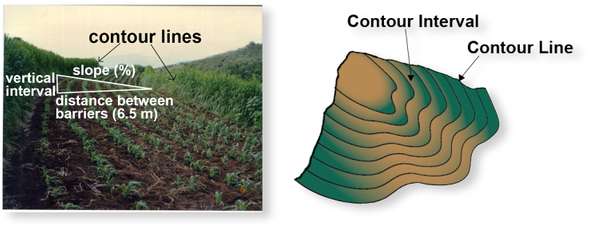
Figure 1. Example of annual crops planted between hedge rows established along contours, which may also be marked in a topographical map. Source: Robert Walle (left) and Stacy Swartz (right)
Many smallholder farmers live in areas with hilly or mountainous terrain. Soil erosion is a major issue in growing crops on steep slopes. When we see contoured plantings across slopes, we know that someone cares about erosion and is doing something about it. The curves are aesthetic, but what do they really do?
To understand what those curves do, we need to know something about contours. Contour lines, drawn on a map or marked on the ground, show lines of consistent elevation (Figure 1). They guide the farmer in tilling and planting across instead of up and down the slope. Farming across the slope is one of the easiest ways for small-scale farmers to conserve soil and water. Below are several ways to mark contour lines along slopes and plant simple conservation practices like live barriers.
A-frame Level and Variations
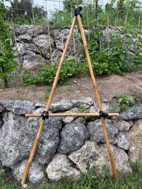
Figure 2. Basic A-frame level with a weighted string made with bamboo. Source: Tim Motis
An A-frame level is perhaps the cheapest and easiest instrument to use when tracing contour lines in the field. Learning to mark contours is a great first step in overall farm design for live barriers and surface drainage. Yarger and Doer (2006) describe how to make a simple and fixed A-frame (Figure 2).
Extensionists improved the basic design to make it easier to transport by bus or motorcycle.
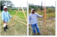
Figure 3. Collapsible A-frame. Source: Robert Walle
A collapsible A-frame folds up, making it easier to transport than a fixed A-frame (Figure 3). Follow these steps for the construction and use of the collapsible A-frame level.
- Get two narrow boards (3.81 cm [wide] x 2.54 cm [thick]), each of them about 2.1 m long. These will be the “legs and feet” of the A-frame. One other board, at least 1.5 m long, will be the cross-section of the A-frame level.
- Join the legs a few centimeters from the end, with a single nail through both boards (you can also use a bolt with a wing nut). Make sure that the “A-frame” can collapse or fold using the one nail or bolt as a pivot or hinge.
- Nail or bolt the cross-section about 1 m from the bottom or top of each of the legs. This should form an “A” shape. Leave one of the nails “loose” so that it is removable and so the crossbar can fold or rotate to be alongside the legs when they fold.
- You can use bolts with wing nuts or easily removable nails for re-assembling the level quickly in the field.
- On the nail or bolt at the top of the A-frame level that holds both legs together, hang a weight bound on a cord to serve as a plumb line (often called a plumb bob). Make sure that the weighted string is long enough to pass perpendicular to the crossbar.
- Each time you use an A-frame, you need to calibrate it.
Videos showing how to build and use an A-frame:
Making and Using an A-Frame Level: http://edn.link/wzncnx
How to Build and Use A-Frame Level: http://edn.link/mgtt47
A-frame with bubble Level (Figure 4)
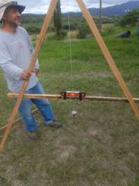
Figure 4. A-frame level with bubble level attached. Source: Robert Walle
The A-frame level, in its most basic form, has a string with a weight (e.g., a rock) on the end, that forms a plumb-line. Alternatively, you can mount a small bubble level on the crossbar of the A-frame. Using a bubble level speeds up the taking of individual measurements in the field when marking the contours, as you do not have to wait for the plumb-line to stabilize. The bubble level A-frame will be accurate as long as the lengths of the two legs are the same and the distance from the bottom of a leg to the horizontal crossbeam is same for each leg.
Remember, before using collapsible and all A-frames, users should calibrate them. Instructions are given in table 1.
| A-frame with a plub line1 | A-frame with a bubble level |
|---|---|
| 1. Place the A-frame on a relatively flat surface (does not have to be perfectly level). | 1. Place one leg of the A-frame on a relatively flat surface (does not have to be perfectly level). |
| 2. Mark the spot on the ground or other surface where each leg of the A-frame was placed in step 1. | 2. Keeping the first leg of the A-frame at the same spot as in step 1, rotate the A-frame to find a spot where the bubble is centered. |
| 3. Wait for the plumb line (string) to stop swinging and then mark where it intersects the crossbar. | 3.Mark the two spots where the legs touch the ground or other surface. |
| 4. Turn the A-frame 180° and place the legs on the same two spots (marked in step 2) and again mark where the plumb line intersects the crossbar. | 4. Turn the A-frame level 180° and place the legs on the same two spots. |
| 5. Halfway between the two marks will be level. Mark this point prominently. | 5. Check to see if the bubble is still centered. If not, adjust the placement of the crossbar or adjust the bubble level with shims under it. |
| ¹See Yarger and Doerr (2006) for similar instructions. | |
Alternatives to the A-frame level
Water level
Make a simple, accurate, U-shaped water level using zip ties, string, or clamps to attach each end of a length of transparent tubing to a 1.5-m long stake marked every 1 to 2 cm with the 0-cm mark at the top of each stake (see Lancaster, 2019 [http://edn.link/wjy2ha] for instructions). The length of the tubing will correspond to the desired distance between markings used to determine the contour lines. With the tubing filled with water and bubbles removed, points of constant elevation are those where the water level is the same on both ends (as indicated by the markings on each stake). These points are marked along the contour in a manner like that with the A-frame.
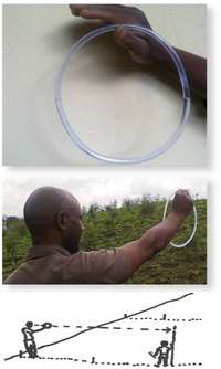
Figure 5. Using a basic water ring in East Africa. Source: ECHO East Africa Staff
The longer the distance between the two ends, the more water you will need to fill the tubes. Add food coloring or any colored fluid available to increase visibility. Another water-based technique called the Water Ring (Figure 5) is described by Kinsey (2013) in Issue 2 of ECHO East Africa Notes.
Basic hand-held sight level
Extensionists increasingly use basic hand-held sight levels because they are very simple to use over longer distances. The hand level is also simple to transport, a definite advantage for extensionists on the go.
An aperture allows sighting along a straight line. A prism reflects a small, attached bubble level on the top of the level, so you can see the bubble as you look through the aperture. You will need two people to take measurements. One person will use the level to sight along a level line and guide the other person holding a stick with a marked level point. Section 6.4 of an FAO training manual (Brouwer et al., 1985), entitled “Elements of Topographic Surveying” explains and diagrams steps for marking the level point and points of constant elevation along a contour.
Lasers and total station
Various laser levels (including total stations) are increasingly available. The total station is a survey instrument that measures the X, Y, and Z coordinates of any point. They are unnecessary for contouring on the small farm but are useful for designing ponds and managing drainage over long distances (e.g., for furrow irrigation). A total station may not be feasible for small farmers, but some extension agents will have access to one.
Measuring the slope
The slope of a parcel of land is the vertical “fall” of the land’s surface, divided by the distance between the same points from which this “fall” is measured.
An A-Frame easily measures the slope in the field. Put one leg of the A-frame on a point on the soil surface and the second leg in the air above the downslope surface. When the A-frame is level, measure the distance above the soil surface, divided by 2 meters (or the length of the base of the A-frame [distance between the bottom of each leg of the A-frame]). This is the slope of that section of land. Take and record several measurements over similar areas.
Do this for each section where the slope is relatively equal. Where the slope differs, the distance recommended between conservation practices (e.g., rock or vegetative barriers) will be different. Remember to consider aspects of the natural formations and “lay of the land”.
Limits to effective contour cultivation
The Natural Resources Conservation Service (2017) found contouring alone is most effective on slope lengths 30.5 to 122 m long. This corresponds to slopes of about 0.5 to 4.5 percent. Societal and economic realities relegate many small-scale farmers to slopes much greater than these. Contour planting/tillage are not sufficient alone but are the first steps in controlling erosion. Large intense storms on hillsides can generate enough runoff and rill erosion to overtop or “melt” the ridges left by tillage.1
Therefore, on sloping lands, it becomes necessary to augment contour cultivation with soil conservation barriers to shorten the slope length 2 and reduce the erosive forces of water. Conservation structures like live barriers physically detain eroded soil and prevent erosion further downslope. Contouring with related soil conservation techniques can slow down runoff water and allow the soil to absorb more water. They enhance water management by channeling excess water and encouraging rainwater to seep into the ground in dry regions. By reducing runoff, along with pesticides and nutrients that the runoff may contain, contamination of surface water is also reduced. These structures are most effective when established along marked contours. They can be live barriers, hillside ditches, swales, or agroforestry plantings. Below we focus on live barriers.
Live Barriers for Erosion Control
Live barriers are simply plantings along the contour to break up the formation of rills and eventually gullies when possible (Garrity, 2000). They also function to retain eroded sediments (Walle and Sims, 1998) and form natural terraces. Live barriers across the gully can effectively treat small gullies in the field (World Bank, 1987).
Live barriers are the easiest conservation practice to install (Garrity, 2000). For best effect, it is essential to establish them as close to the contour as possible. Once marked, farmers can plant live barriers along the contour lines. Deposition of sediments behind the barriers smooths out contour line imperfections. The distance between barriers varies with the slope. Table 2 gives the recommended distances based on slope for simple live barriers. Note in the table that the distance between barriers decreases with increasing slope and that distance figures are based on a vertical difference in elevation of 2 m (recommended by the Vetiver Network International as optimal for erosion control).
| Slope (degrees) | Slope (%) | Distance between barriers (for a 2 m vertical interval) |
|---|---|---|
| 1 | 1.7 | 114.6 |
| 2 | 3.5 | 57.4 |
| 5 | 8.8 | 23.0 |
| 10 | 17.6 | 11.6 |
| 15 | 27.0 | 8.0 |
| 20 | 36.4 | 6.0 |
| 25 | 46.6 | 4.8 |
| 30 | 57.7 | 4.0 |
| 35 | 70.0 | 3.4 |
| 40 | 84.0 | 3.2 |
| 45 | 100.0 | 2.8 |
| Source: Vetiver Network International (2021) | ||
Distance between barriers should also accommodate farmers’ needs. Account for factors such as turning space needed for animal traction or other tillage equipment. Most importantly, she/he will factor in the cultivated area they need to live and generate income on the hillside farm. If the barrier does not produce a commodity that is useful to the farmer, they will usually extend the distance between the barriers to take up less cropland.
Adjusting the distance between the barriers
Many of the distances recommended between barriers are too narrow for the small-scale farmer. This highlights the necessity of the barriers to produce something of value to the farmer. Farmers must consider agroforestry and fodder crops to provide for animals. Trees will take up more space than most annual crops. Extending these distances so that they are more favorable to the farmer is a common modification.
When increasing distances, important things to consider are the barrier species; their effectiveness in soil and water conservation; and the crop space needed. For example, agroforestry trees alone are usually less effective barriers than grasses. In combination, however, they can provide leguminous fodder while conserving soil and water.
Types of live barriers
Live barriers should be dense at the soil surface so that overland flow does not form rills. The barriers should also be dense enough to catch, or deposit eroded sediment from above.
This is a problem with many agroforestry species; the tree roots stabilize the soil, but rills find their way around tree trunks and laminar erosion still occurs and continues downslope. To trap eroded soil, farmers often combine live barriers with agroforestry. Table 3 lists some options and uses for various tropical species used for live barriers.
| Common Name | Scientific Name | Legume | Fodder | Soil and Water Conservation |
|---|---|---|---|---|
| Gliricidia | Gliricidia sepium | yes | yes | yes |
| Leucaena | Leucaena leucocephala | yes | yes | yes, caution- can become weedy |
| Pigeon pea | Cajanus cajan | yes | yes | bi-annual, needs replacing |
| Napier/King grass | Pennisetum purpureum | no | yes | fair, maintain high density |
| Sugar cane | Saccharum officinarum | no | yes | fair, maintain high density |
| Lemon grass | Cymbopogon citratus | no | no | yes |
| Pineapple | Ananas comosus | no | no | poor |
| Vetiver | Vetivaria zizanoides | no | yes | yes, high |
| Sisal | Agave sisalana | no | no | poor |
| Setaria | Setaria spp. | no | yes | yes |
| Guatemala grass | Tripsacum laxum | no | yes | yes |
| Guinea grass | Panicum maximum | no | yes | yes, caution- can become weedy |
| Albizia | Albizia spp. | yes | yes | fair, maintain high density |
| Calliandra | Calliandra spp. | yes | yes (10-30% diet) | fair, maintain high density |
| Flemingia | Flemingia | yes | yes | fair, maintain high density |
| Mulberry | Morus alba | no | yes | fair, maintain high density |
| Orchid tree | Bauhinia spp. | yes | yes | fair, maintain high density |
| Grevillea spp. | no | no | fair, maintain high density |
Grasses such as such as napier/king grass will eventually form a dense barrier, but the plant crowns dry and leave spaces in the barrier. Some grasses can provide fodder for animals. Many grasses are invasive, but animal traction or digging hoes (with more effort) can be used to control rhizomes. Experience has proven vetiver grass to be effective and a good option for farmers. It does not provide any additional benefits, such as food or fodder. There are a lot of effective options.
While establishing live barriers, manage weeds and irrigate as needed. If there are gullies in the field, it is best to treat them with appropriate erosion control measures before they become larger.
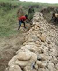
Figure 6. Making a soil conservation barrier with available rocks in East Africa. Source: ECHO East Africa Staff
Farmers can use the rocks in their fields to build stonewalls aligning with the contours (Figure 6). Larger constructed stonewalls should have the correct anchoring as needed. They require an excavated anchor as erosion can undercut the base. Sometimes smaller stones are just arranged on the contour. Making use of the present rocks while improving your cultivation environment is very important. Rocks can also be important in the building of dikes and other structures.
Closing Note on Extension
Contouring is a simple way to conserve soil and water on mild slopes and is the foundation for soil and water conservation on hillsides.
It’s important for extension agents to be aware of labor costs for soil and water conservation. Many times when extensionists introduce soil and water conservation concepts, the farmers will say “what you brought here is more work! “ Many times, in reference to increasing erosion, farmers will comment on how the rocks “grow.” Even though the process of sheet erosion may not be visible, the deposition of eroded material downslope is. Examination of the soil surface for rill erosion is another example of low-cost extension methodology. These are useful for highlighting the importance of erosion control in extension/demonstration efforts conducted in settings like farmers’ fields and farmer field schools (Walle and Sims, 1998). Low-cost techniques like live barriers and agroforestry can provide solutions and promoting them with examples is an effective extension methodology.
References
Brouwer, C., A. Goffeau, J. Plusjé, and M. Heibloem. 1985. Elements of Topographic Surveying. Irrigation Water Management Training Manual No. 2. Food and Agriculture Organization of the United Nations.
Garrity, D. P. 2000. Contour farming based on natural vegetative strips: Expanding the scope for increased food crop production on sloping lands in Asia. Environmental Dev, and Sustainability 1 (Special issue). pp. 323-336.
Kinsey E. 2013. A combination of approaches to conserve soil and water. ECHO East Africa Notes No. 2.
Lancaster, B. 2019. Appendix 1: Water Levels, A-Frame Levels, and Laser Levels. In: Rainwater Harvesting for Drylands and Beyond, Vol 2 2nd Edition.
NRCS. 2017. Conservation practice standard. 330.
USDA. 2001. Revised Universal Soil Loss Equation. Version 2 (RUSLE2) HANDBOOK. USDA RUSLE Team.
Vetiver Network International. 2021. How to plant. https://www.vetiver.org/vetiver-grass-technology/how-to-plant/
Walle, R. and Sims, B.G. 1998. Natural terrace formation through vegetative barriers on hillside farms in Honduras. American Journal of Alternative Agriculture. 13(2): 79-82. https://doi.org/10.1017/S0889189300007700
Yarger, L. and B. Doerr. 2006. A-Frame Level. ECHO Technical Note no. 55.
World Bank. 1987. Vetiver: The Hedge against Erosion. World Bank, Wash. D.C.