VITA
Published By VOLUNTEERS IN TECHNICAL ASSISTANCE 1600 Wilson Boulevard, Suite 500, Arlington, Virginia 22209 USA Telephone: (703) 276-1800, Fax: (703) 243-1865 Telex: 440192 VITAUI, Cable: VITAINC Internet: vita@gmuvax.gmu.edu, Bitnet. vita@gmuvax
Understanding Stirling Engines ISBN: 0-86619-200-X [C]1984, Volunteers in Technical Assistance
PREFACE
This paper is one of a series published by Volunteers in Technical Assistance to provide an introduction to specific state-of-the-art technologies of interest to people in developing countries. The papers are intended to be used as guidelines to help people choose technologies that are suitable to their situations. They are not intended to provide construction or implementation details. People are urged to contact VITA or a similar organization for further information and technical assistance if they find that a particular technology seems to meet their needs.
The papers in the series were written, reviewed, and illustrated almost entirely by VITA Volunteer technical experts on a purely voluntary basis. Some 500 volunteers were involved in the production of the first 100 titles issued, contributing approximately 5,000 hours of their time. VITA staff included Leslie Gottschalk as primary editor, Julie Berman handling typesetting and layout, and Margaret Crouch as project manager.
William Beale, author of this paper, is president of Sunpower Incorporated. He has designed, developed, manufactured, and marketed Stirling engines in Bangladesh and other developing countries, and has published widely in the solar energy field. Reviewers David M. Berchowitz, Michael F. Feeney, Robert C. Wagman, and Francis E. Woodling are also specialists in the area. Artist Fred Heltsley has an engineering background and is a professional technical illustrator on a consultant basis.
VITA is a private, nonprofit organization that supports people working on technical problems in developing countries. VITA offers information and assistance aimed at helping individuals and groups to select and implement technologies appropriate to their situations. VITA maintains an international inquiry Service, a specialized documentation center, and a computerized roster of volunteer technical consultants; manages long-term field projects; and publishes a variety of technical manuals and papers.
I. INTRODUCTION
Stirling engines are external combustion engines that use air or other gases as working fluid. They can burn any solid or liquid fuel as their heat source. This makes them very attractive, particularly in situations where conventional fuels are expensive and hard to obtain. Because some types of Stirling engine are so simple to make and yet so effective, they are excellent choices for power generation in developing countries.
This paper describes the basic Stirling engine, as well as some of the most promising modern varieties. The intent here is to familiarize people in developing countries with the engine's operation and range of applications.
HISTORY
The Stirling engine was invented by Robert Stirling, a Scottish minister, in 1816. The early Stirling engine had a history of good service and long life (up to 20 years). It was used as a relatively low-power water-pumping engine from the middle of the nineteenth century to about 1920, when the internal combustion engine and the electric motor replaced it. The hot-air engine was known for its ease of operation; its ability to use any burnable material as fuel; its safe, quiet, moderately efficient operation; and its durability and low maintenance requirements. It was very large for its small power output, however, and had a high purchase cost. Nevertheless, its low operating cost usually justified choosing it over the steam engine--the only alternative at the time-- which burned much more fuel for the same power and demanded constant attention to avoid dangerous explosions or other failures.
The other major disadvantage of the early hot-air engine was its tendency to fail if the heater head got too hot. This ;as a result of the relatively low heat resistance of the cast iron heater head. The problem was overcome by redesigning the burner, which prevented the engine from overheating. This improvement resulted in safe, but even lower, power operation. Despite this improvement, the Stirling engine could not compete with the cheaper, more powerful internal combustion engine, and it disappeared from the commercial scene.
The advent of newer stainless steels and advances in the understanding of the engine's complex thermodynamic process brought new attention to the engine during and after World War II. The performance of the old hot-air engine was improved and its size and cost were reduced. Its simplicity of construction and operation, and most important, its ability to use rough fuels were retained. These efforts on Stirling engines were almost exclusively aimed at difficult applications that were not appropriate for developing countries--namely, the advanced automotive engine, space power, and artificial hearts. Almost no effort was put into the relatively easy task of designing an engine for ordinary uses. The highly developed countries in which the Stirling engine work was being done did not need a simple engine, so there was no economic incentive to design one.
This situation changed in 1980, when the U.S. Agency for International Development (USAID) funded the development of a simple Stirling engine specifically intended for manufacture and use in developing countries. The engine was designed, built, tested, and delivered to Bangladesh, and copies of it were built and put into operation there. This demonstrated the Possibility of the engine's manufacture in simple machine shops of the type found in many regions of Africa, Asia, and Latin America.
As a result of this and other recent developments, the formerly dim prospects for the application of Stirling engines in developing countries have improved enormously. Plans are now in motion to bring a new design of the Stirling engine into commercial production in a much improved form. This modern version will be much more powerful for its weight and much more efficient; at the same time, it will be as quiet, easy to use, reliable, and rugged as the original engine. Additional models, capable of generating electricity, cooling, pumping water, and serving in other useful ways not possible with the old hot-air engine, are also coming into commercial production.
NEEDS SERVED BY THE TECHNOLOGY
Although the Stirling engine is an old machine, modern materials and design methods make it much more attractive than ever before. The crank-drive Stirling engine is definitely useful to anyone who has solid fuel. This type of Stirling engine can burn any local fuel as its source of heat to produce electricity, pump water, or perform tasks requiring mechanical power such as food processing.
Very simple machines using atmospheric air as working fluid can be built from local materials such as metal containers. People who are inclined to try such designs have a good chance of success.
II. OPERATING PRINCIPLES
BASIC THEORY OF THE TECHNOLOGY
The Stirling cycle is shown in the diagram in Figure 1 . The

basic idea is that when gas in a closed cylinder is moved into the hot part of the cylinder, it expands, its pressure increases, and it can do work. When the gas moves into the cold part of the cylinder, its pressure is reduced. Once the gas reaches the lower pressure, it is compressed back to its original volume. The gas performs more work during its expansion than is required to be put into it during its compression. Thus, the entire cycle results in the net positive output of work.
As shown in Phase 1 of Figure 1, the piston is out (bottom dead center), and the displacer is in as far as it can go. The gas is in the cold space, and the gas pressure is low. (Note that the gas is at the same pressure at any instant in every part of the engine, but that this pressure is changing with time. Because the pressure is low, the piston can be moved in easily to compress the gas at the low temperature. At the end of this compression process, the engine has reached Phase 2, as shown in Figure 1.
Now it is time to increase the gas pressure. This is not done by burning a fuel inside the gas as is done in an internal combustion engine. The gas is moved from the cold space through a series of heat exchangers, which cause it to enter the hot space at a high temperature. Note that the gas in the heater, cooler, regenerator, and hot and cold spaces, is always at the same pressure at any instant, since the gas flow passages are large and do not restrict the passage of the gas.
As shown in Phase 3 of Figure 1, the gas is compressed, hot, and at high pressure. At this point it is ready to expand and to work on the piston. As the piston moves out of the cylinder, the displacer moves with it, in order to keep as much of the gas as possible in the hot space so that the pressure is kept as high as possible to do the maximum amount of work on the piston. This expansion and outward movement of the piston results in the attainment of Phase 4, as shown in Figure 1.
The next step is to reduce the gas pressure by moving it from the hot space through the heat exchangers to the cold space. This is done by moving the displacer from its position, as shown in Phase 4, back to its inward position, as shown in Phase 1. The cycle is now complete. Notice that the piston has expanded the gas by moving outward when the gas is hot and at high pressure, and has compressed the gas when it is cold and at low pressure. Thus, the original plan has been accomplished, and the cycle has produced net work to the outside.
For this four-phase process to continue indefinitely, heat must be continually added to the hot heat exchanger from some outside source like a fire or a solar collector, and the cold end must be continually cooled by a stream of water or air.
You might now wonder how the movements of the piston and the displacer are accomplished, since they clearly cannot move on their own. The answer is that there are at least two ways to make the two components of the simple Stirling engine move as we wish: (1) we can attach them to cranks through connecting rods, as is commonly done in automobile engines; or (2) we can use gas forces in a carefully designed way so that they bounce on gas springs, with the displacer always ahead of the piston in its in-and-out oscillation. Of the two methods, the use of cranks called the crank-drive, or kinematic Stirling, is the more easily understood method. The second method, which uses oscillating motions of the piston and displacer on springs, is called the free-piston Stirling. The crank-drive Stirling is easier to understand yet harder to make, while the free-piston Stirling is harder to understand yet easier to make in at least some of its forms.
III. DESIGN VARIATIONS
This section of the paper describes a variety of promising Stirling engines. It emphasizes their physical characteristics, advantages and disadvantages, applications, and fuel efficiencies.
TYPES OF STIRLING ENGINES
Crank-drive Stirling Engine
A schematic of the crank-drive Stirling engine is shown in Figure 2, and a crank-drive Stirling engine pumping water is
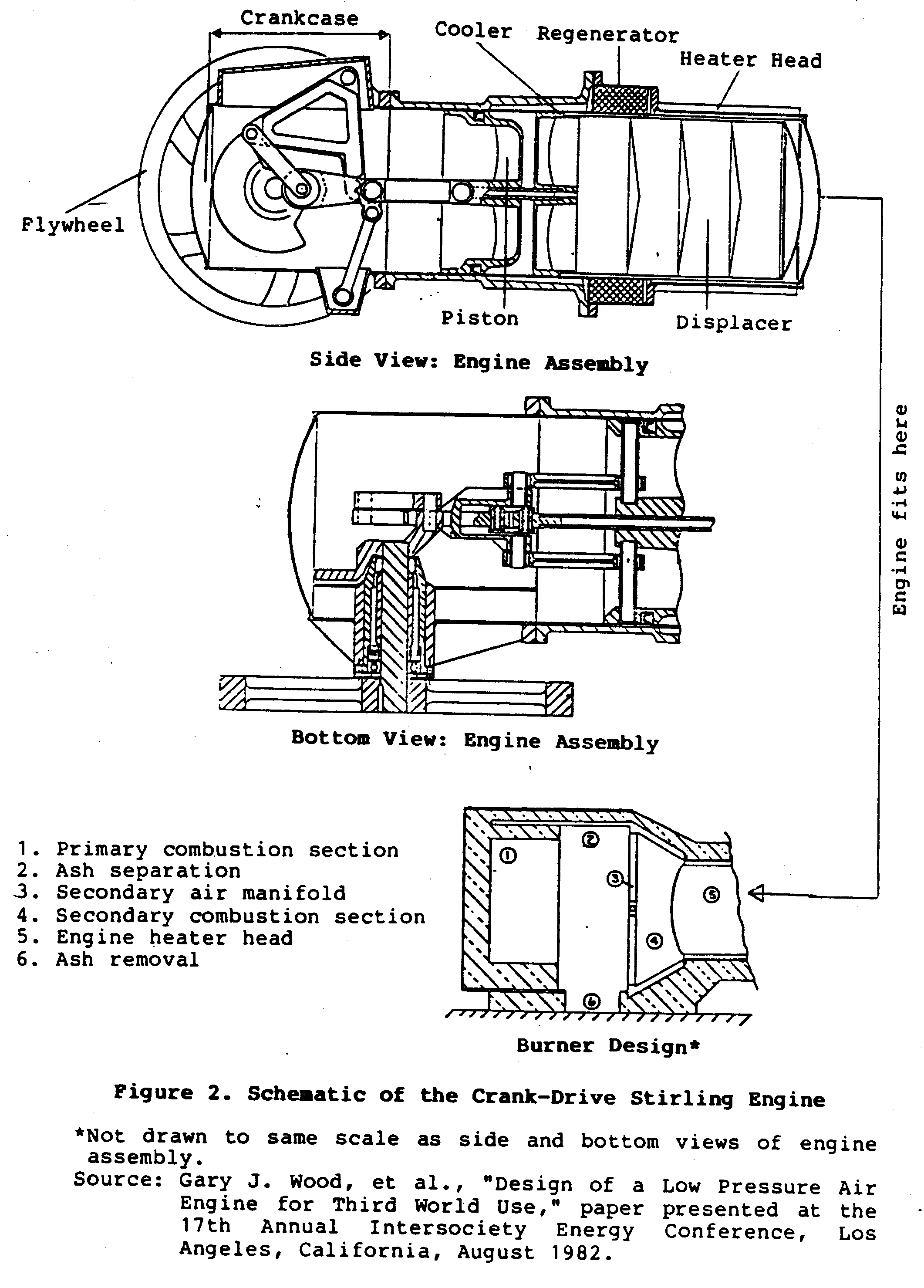
shown in Figure 3. While this engine is unusually large for
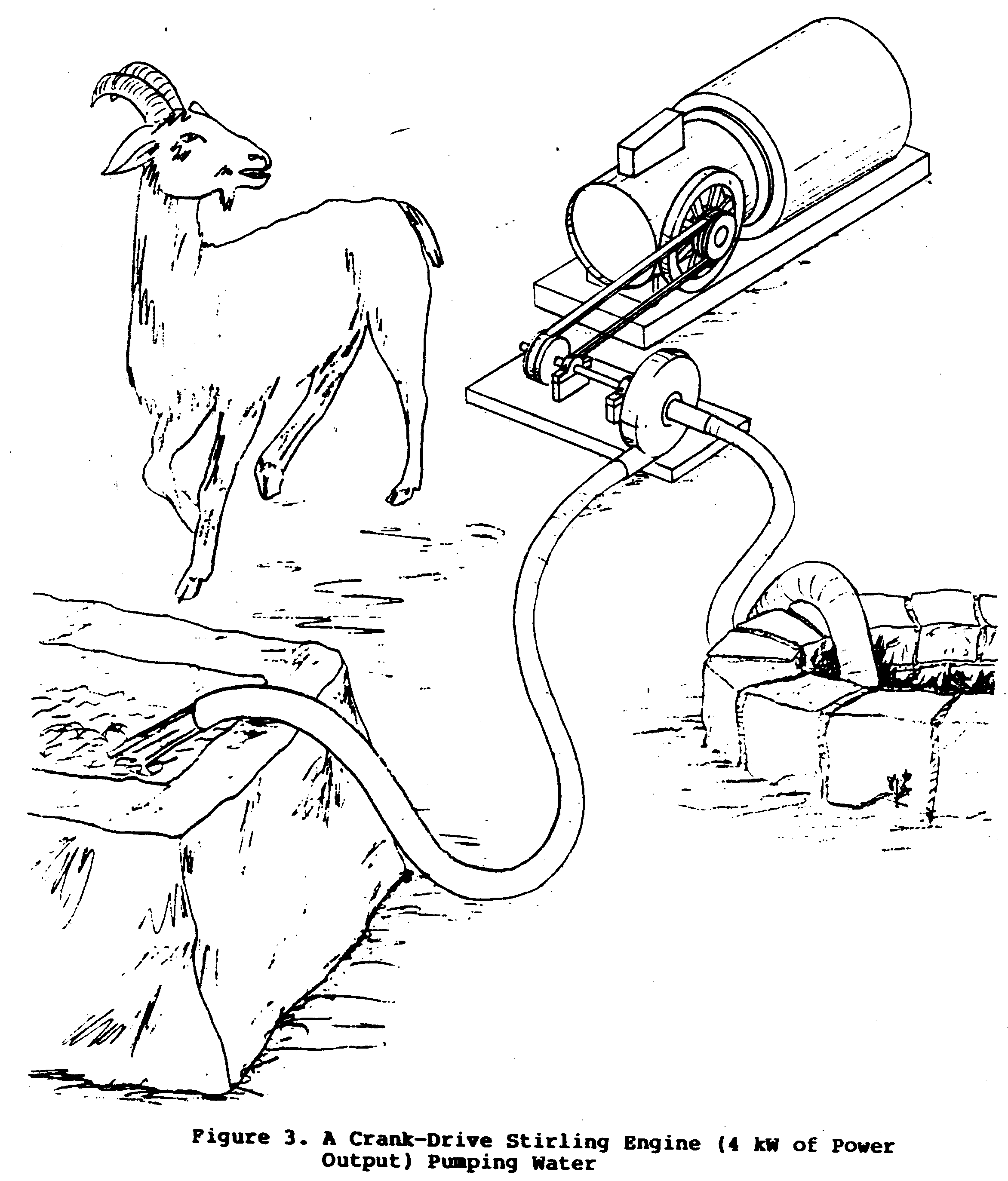
the small amount of power (5 kilowatts) it produces, it is nevertheless very simple to make and operate. It uses no oil in the crankcase; here it is important to avoid getting oil into the hot working parts of the engine, because it could block the flow of air through the heat exchangers and also cause an explosion. Any of the following three types of bearings can be used: sealed roller bearings, ball bearings, or unlubricated bushings made of a plastic like Teflon. If necessary, the ball and roller bearings can be replaced by journal bearings and sealed in grease. Since the engine is slightly pressurized, up to about atmospheres (atm), it uses a simple crank shaft seal to keep the air in, and a small air pump to maintain the pressure against slow leakage past the seal. The air pump as well as all other accessories needing power are driven directly from the rotating engine shaft.
Other accessories requiring shaft power. are the auger feeding the fuel, the combustion air blower, and the cooling water pump and radiator fan.. With these accessories, the engine is able to work without any other source of power, and needs only fuel to operate.
Typical operating instructions are as follows:
- Make sure the engine is in good operating condition and the hopper is full of fuel.
- Start a fire in the burner with kindling (e.g., wood shavings, dried leaves), and operate the air blower by hand until the interior of the burner is sufficiently hot to receive and ignite the fuel from the fuel feed.
- Hand operate the combustion air blower and the fuel auger until the heater head of the engine reaches a moderate temperature (about 300[degrees]C). The engine is now ready to start.
- Turn the flywheel over, and the engine should begin to run on its own power immediately (easy starting is one of the best features of this engine).
- Allow a short time for the engine to pressurize itself and to drive the burner until it is at full operating pressure and temperature. During this time, the engine will gradually grow stronger and more capable to do work. The load can be increased as the engine grows stronger. This happens automatically if the engine is attached to loads such as centrifugal water pumps or generators, but loads such as saws and milling machines have the capability to stall the engine if their load is applied too quickly. If the engine is stalled, it can be restarted immediately by unloading it and turning the flywheel again.
- Once the engine is up to full power and doing its work, the operator needs only to keep the fuel hopper full and maintain a load. If the load is removed for any reason, the engine will speed up, but not to a harmful degree; it will quickly reach a speed at which its power output drops to zero, and it will continue to run.
- When it is time to shut off the engine, simply cut off the fuel and the engine will slowly come to a stop. It can be stopped more quickly at any time by releasing the internal pressure, which reduces the power to a low value.
Since there are very few critical adjustments of fuel, air, or water flow, and there is no fuel injector or spark system, the crank-drive Stirling engine is extremely reliable and easy to run. But in order to achieve maximum performance it is important to make correct adjustments of these flows, which someone with only a little experience can do easily,
Because of its ease of operation, durability, local manufacturability, and the ability to use any local fuel as its heat source, the modern crank-drive Stirling engine is remarkably well suited for power generation in developing countries. Plans for this Stirling engine will be available from USAID in 1984 or 1985. Commercial production of the engine, or versions of it, is expected to begin in 1984.
Simple Free-Piston Engine
Figure 4 portrays a slow-speed free-piston engine, which is a
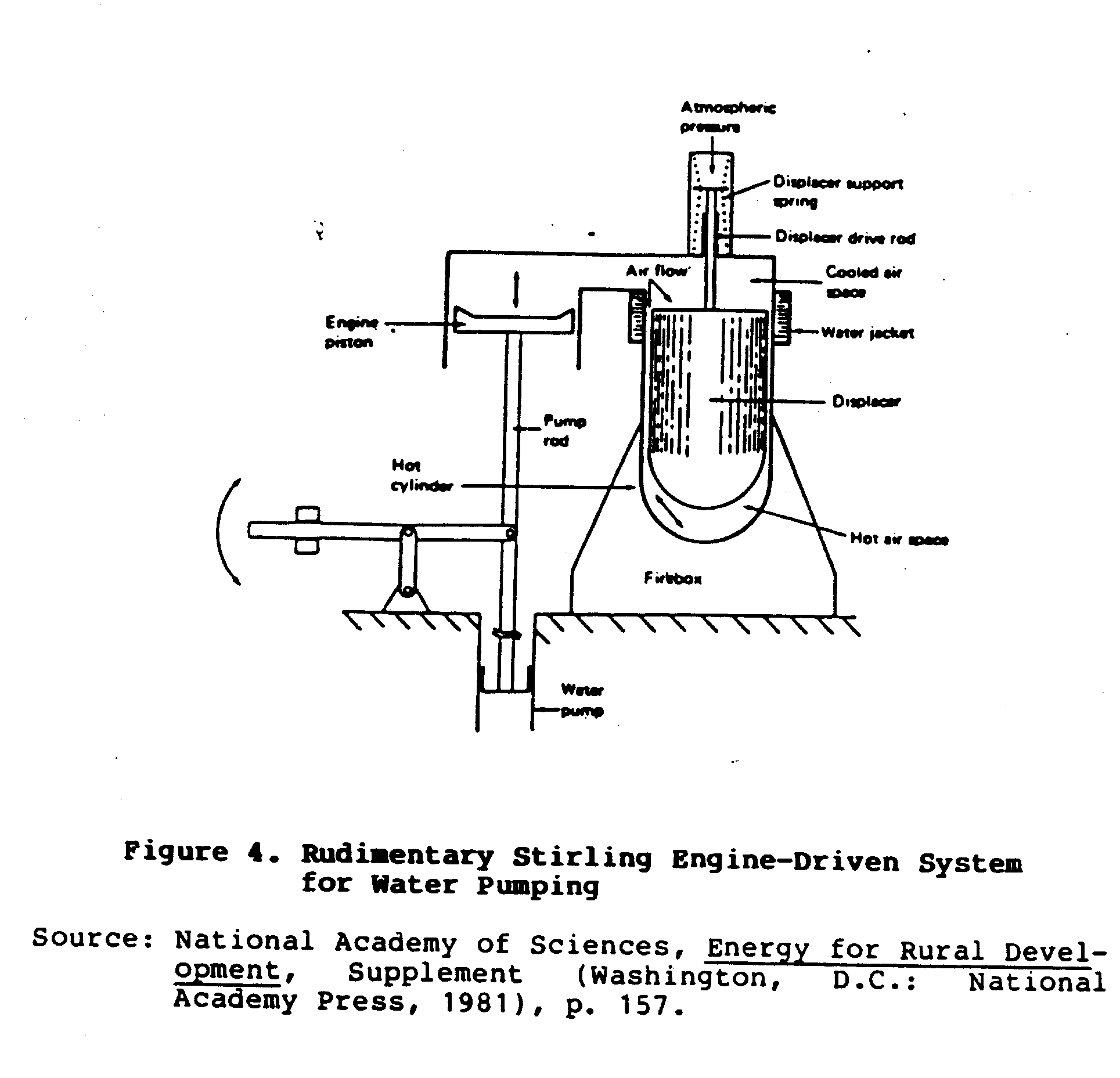
simple version of the Stirling engine. This engine is almost the ultimate in simplicity compared to other Stirling engine designs. It is the so-called overdriven configuration in which the displacer is floated by springs and will move spontaneously either up or down under the influence of the slightest force or disturbance of the pressure inside the engine. The great advantage of this arrangement is that the engine is not only self-starting (requiring only that a good temperature difference be established between the hot and cold spaces), but it will adjust to any load, even a complete stopping of the piston, and still cycle up and down. Thus, the engine is very. forgiving and easy to operate. Its major disadvantage is that it is too big for its small power output; this is because it uses atmospheric air as working fluid and operates at a very low frequency. Counterbalancing this disadvantage are the very high lift capacity and efficiency of the simple positive displacement pump which the engine can operate.
Dimensions
The displacer and piston diameter can be the same. The displacer should be at least as long as its diameter, with a maximum length of three times its diameter, and the end cap should. be domed to allow some strength against collapse. The gap between the displacer and the cylinder should be about one to two hundredths of the diameter, with a preference for the smaller gap. In order to keep the displacer centered, it should have raised bumps of the gap thickness that rub slightly against the cylinder in its cold section.
The heater section length should be about one fourth of the displacer diameter, and the cooler about the same. This leaves one half of the displacer to act as a regenerator, which serves to store the heat of the air as it comes from the heater to the cooler, and releases it to the air as it comes back from the cooler to the heater. This action increases the fuel efficiency of the engine.
The displacer movement available should be about one third of its length.
The displacer drive rod should cover about 15 percent of the area of the displacer cylinder. The drive rod should fit closely in its sleeve but be free to move.
Materials
The best material for the displacer hot end is any one of the 300 series stainless steels, such as 304, 316, or 321. These are also called 18-8 type stainless, the kind used in cooking pots. The hot end of the displacer cylinder must be of stainless steel also, or possibly ceramic if it can be made airtight. Of course, if only short-term experiments are the aim, then ordinary carbon steel sheet can be used for both displacer and heater head.
The displacer itself can be quite thin, provided that a non-return valve is installed in its cold end to allow the interior to reach the maximum cycle pressure and stay there. Otherwise, the displacer could collapse under pressure. It is also important to make the displacer shell thick enough to prevent its collapse under outside pressure.
The rest of the engine can be of steel, cast iron, aluminum, or whatever is locally available, since it is not exposed to heat. Care should be taken to make the displacer as light as is practical. Otherwise, it will respond too slowly to gas pressure and will not develop the lead in motion over the piston necessary to accomplish the Stirling cycle.
Energy Output
A simple free-piston engine with a 60-cm diameter displacer, operating at one cycle per second, can be expected to produce about 500 watts of power (50 liter-meter/sec) of pumped water. Of course, as with any first attempt, the actual output could be much less.
Free-Cylinder Engine
Another excellent candidate for use in developing countries is the free-cylinder engine. It shares many of the virtues of the crank-drive Stirling engine and is even simpler to make. Moreover, because it is hermetically sealed, it is impervious to damage from outside contaminants. However, because it is basically a reciprocating output machine, it must have some sort of power-transforming device such as a ratchet drive and gearbox to provide rotary motion if such is needed. There are many uses for simple reciprocating motion, such as water pumping, and in these uses the free-cylinder engine is an excellent choice.
Figure 5 shows a model of a typical free-cylinder engine used
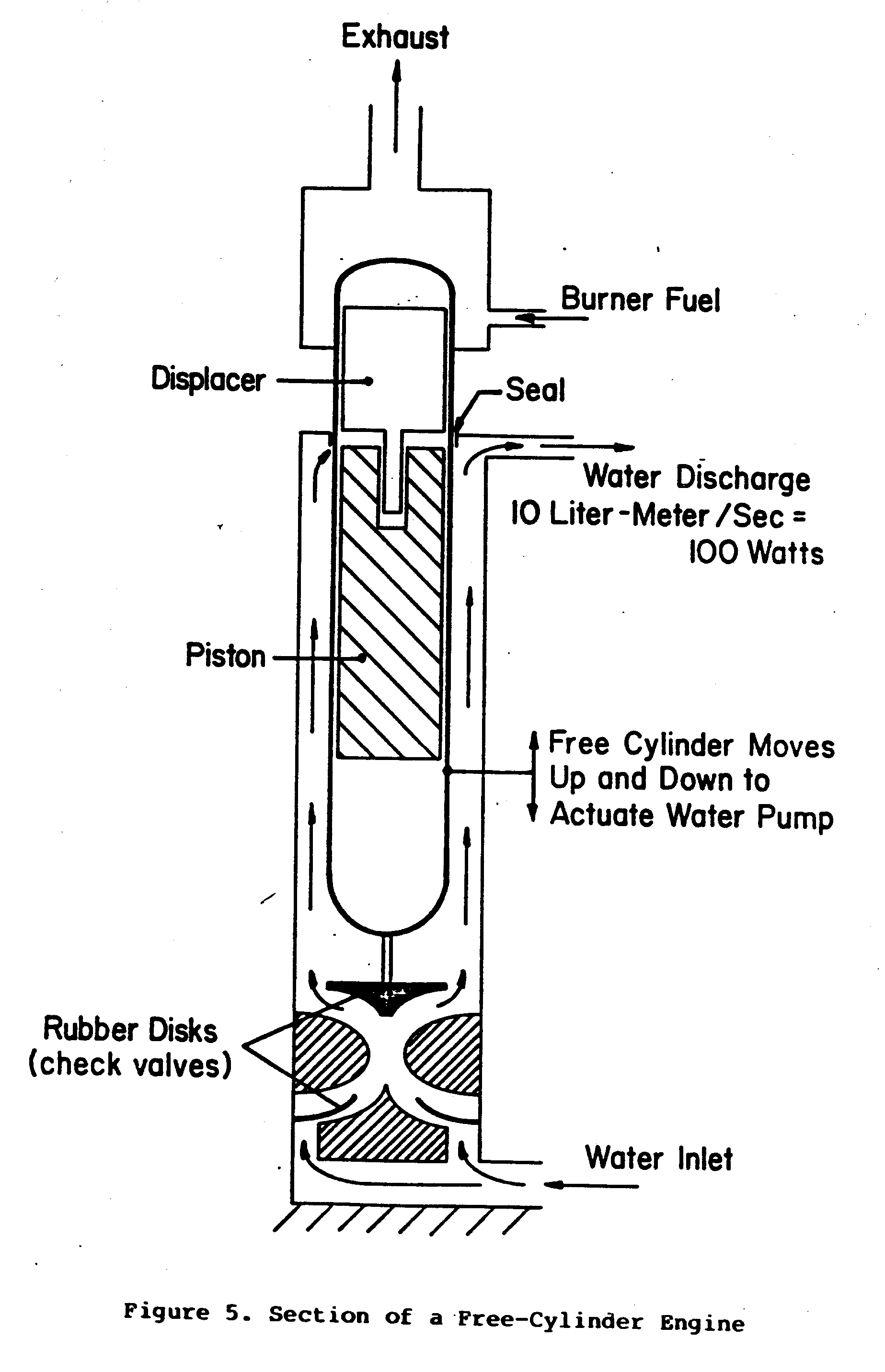
as a water pump. The power is taken from the oscillating cylinder, which moves in reaction to the opposite motion of the heavy piston inside. The displacer is driven by the gas pressure on its rod, which is attached to the piston.
The free-cylinder engine, like all Stirling engines, can operate on any heat source. Use of a ratchet drive permits the high-frequency short-stroke free-cylinder engine to drive any load requiring a rotating shaft, and thus greatly enhances its utility.
The free-cylinder engine used as a reciprocator can easily drive not only fluid pumps but air or gas compressors as well. It can also drive refrigerant pumps for food preservation.
Starting the free-cylinder engine can be automatic if the engine is in a vertical position; otherwise, a slight jar is necessary to start the initial motions, after which the engine will run vigorously as long as the temperatures prescribed for both the hot end and the cold end of the cylinder are maintained. The temperature required is usually from 400 to 700[degrees]C on the hot end and up to 100[degrees]C on the cooling jacket.
Since there are only two moving parts inside the cylinder, the free-cylinder engine is even easier to make than the crank-drive Stirling engine described earlier in this paper. Moreover, Since the cylinder is hermetically sealed, the engine does not need an air pump or a sliding seal to contain its working gas. Therefore, the engine can operate at a high pressure, say up to 15 atm, making it very compact and cheap for its power.
Duplex Stirling Engine
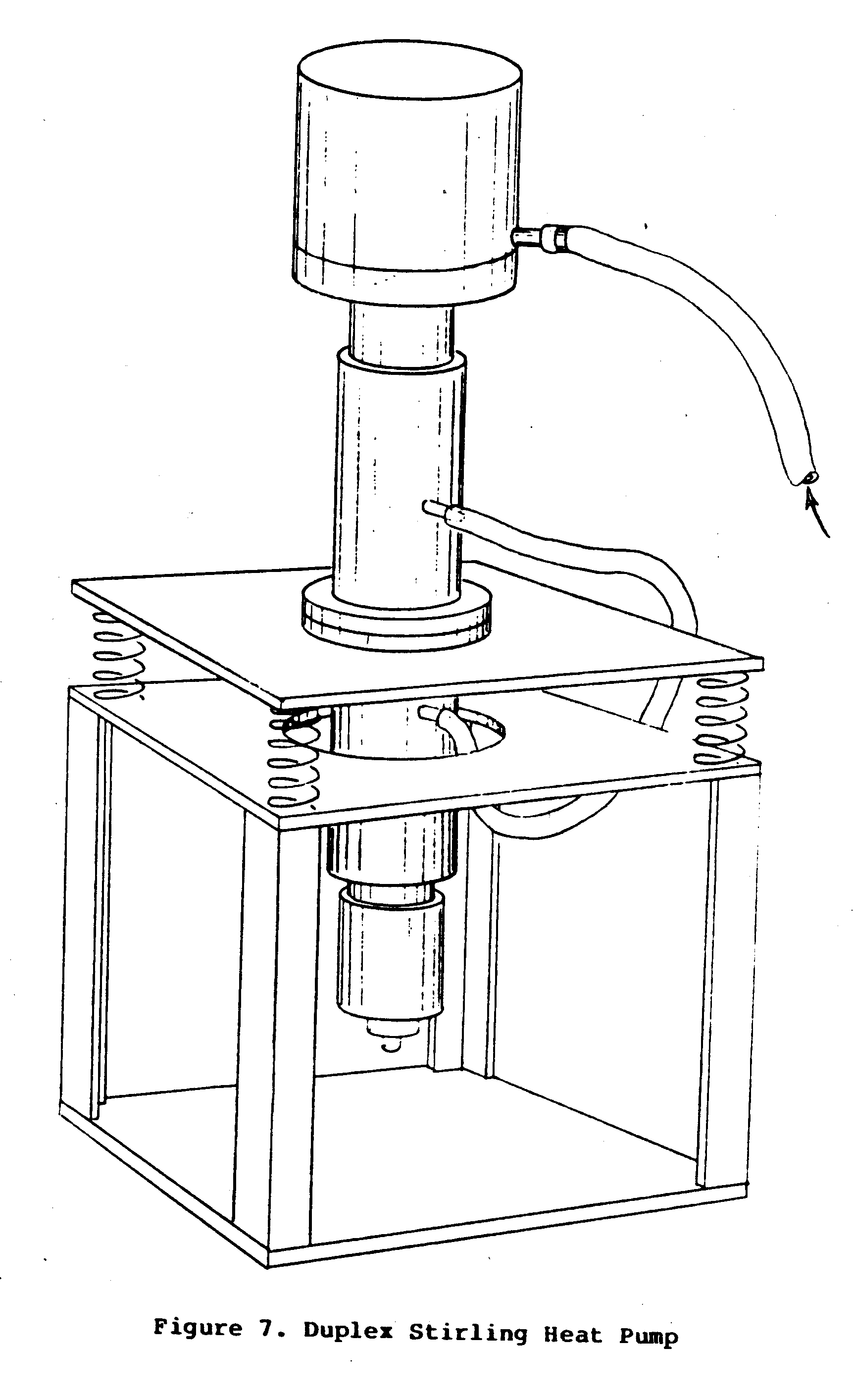
The duplex Stirling engine is a heat-driven cooling machine; that is, it takes in heat and produces cold without producing any other external effect. It is very simple, almost as simple as the free-cylinder water pump, and is very fuel-efficient if carefully designed. Figure 6 shows a typical cross-section
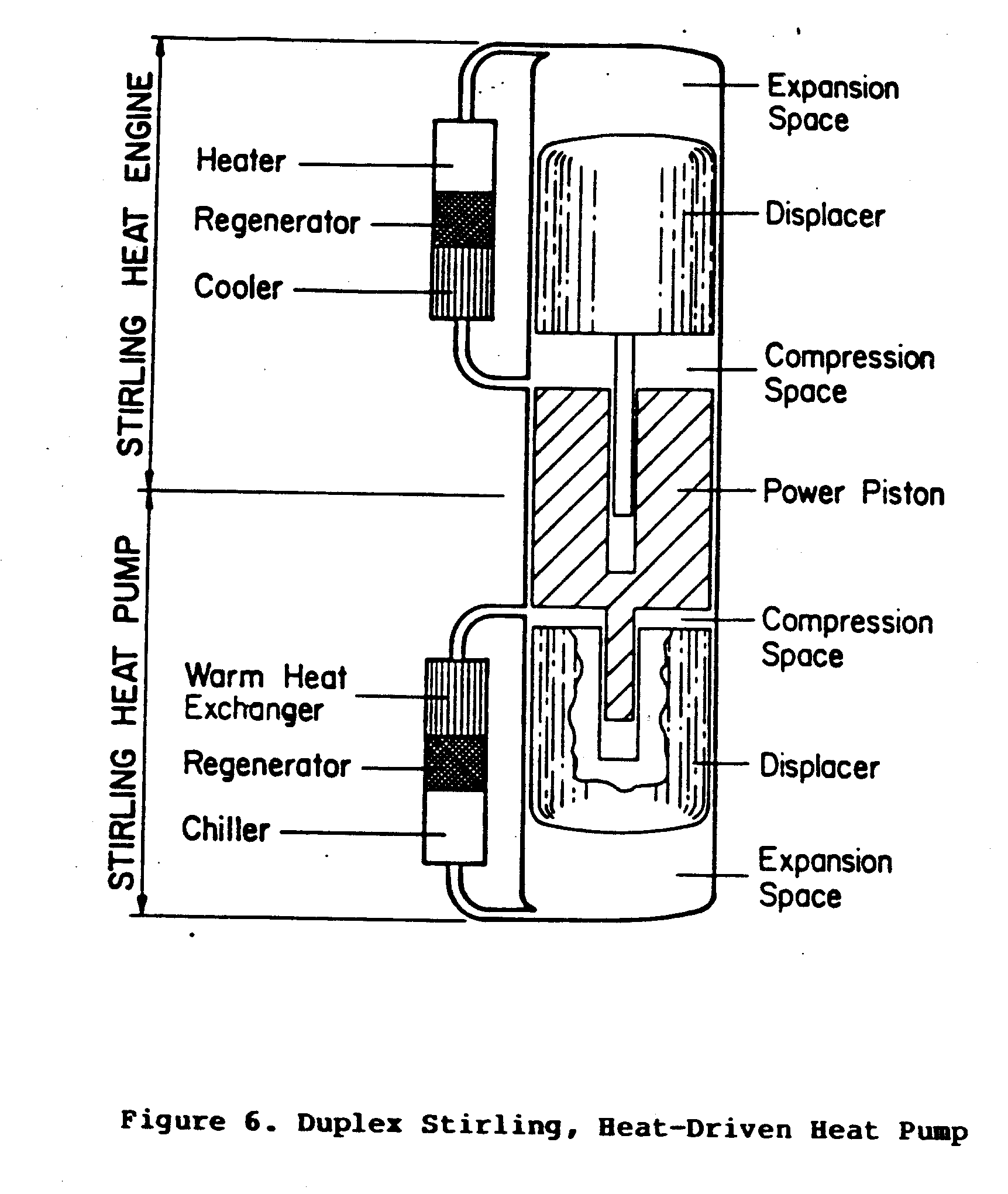
of the duplex Stirling engine designed as a heat-driven food refrigerator. Figure 7 shows it in operation.
The basic idea behind the operation of the duplex Stirling engine is that when driven, it becomes a heat pump. In the duplex Stirling, a Stirling engine is used to drive a Stirling heat pump. This can be done with only three moving parts--the hot displacer, the piston which acts as the piston for both the heat engine and the heat pump, and the cold displacer. This combination of parts makes a simple and effective heat-drive heat pump, which can be scaled to any size or temperature range, from very cold temperatures necessary to liquify air to mild temperatures useful for space cooling.
The duplex Stirling engine will be commercially available within the next few years, probably as a portable, foodstoring freezer-refrigerator in small sizes.
Free-Piston Alternator Engine
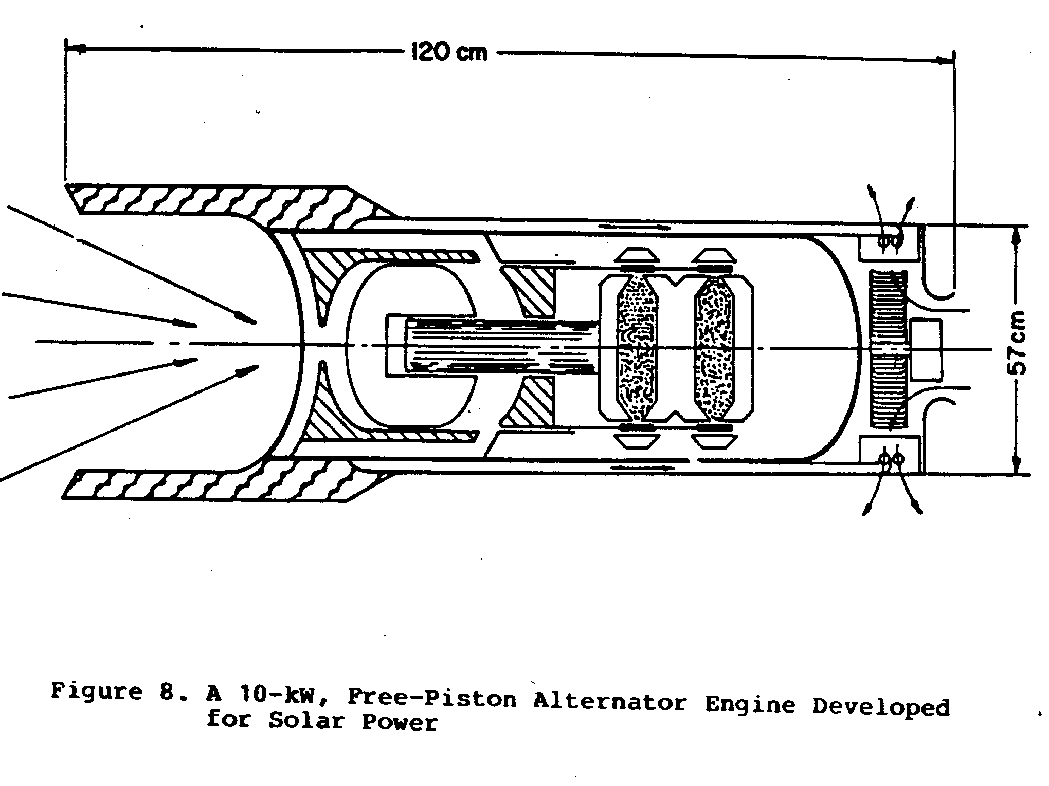
Recent efforts to develop the free-piston alternator engine have produced outstanding results. While the engine will not become a commercial item as quickly as the crank-drive Stirling engine, it will follow with only about a year's delay. The one most developed at the moment is a 1-kW output machine that has excellent fuel efficiency, promises long life, and is very compact. This machine is not simple, however, and requires highly sophisticated manufacturing procedures and materials. On the other hand, because it is hermetically sealed, it cannot be damaged by any sort of rough treatment, although the control system and other auxiliaries are not so invulnerable.
The free-piston alternator engine is ideally suited to the task of developing electricity from solar energy, especially when matched to a low-cost plastic film concentrator of the type now coming on the market. Such machines are being actively developed in sizes up to 10 kW, and could be available in even larger sizes in a few years. The one shown in Figure 8 has a 10-kW output.
USES OF THE STIRLING ENGINE
Irrigation with Biomass
Both the crank-drive Stirling engine and the free-cylinder engine are practical for irrigation with biomass, provided that ample biomass is available for fuel as well as cheap labor to feed the engine with fuel and tend its operation. The crank-drive engine is practical from about 500 watts to tens of kilowatts of delivered power, but in power above 3 kW it will require a wheeled cart to transport it. The free-cylinder engine makes a good irrigation pump up to about 500 watts. Either engine can drive both shallow well and deep well pumps, as well as low-lift ditch pumps. Also, the electric generator free piston can be attached to an electric pump for this service.
Electricity Generation--Small Sizes--Solid Fuel
Both the crank-drive Stirling engine and the free-piston alternator engine are practical for this use. The free-piston alternator engine has the advantage of very low noise and long life, but is harder to repair in the field. The crank-drive Stirling engine is simple, easy to repair, and cheaper, and can be manufactured in simple repair shops; however, it is not as fuel efficient.
Electricity Generation - Village Power - Solid Fuel
Here again, both the crank-drive Stirling engine and the free-piston alternator engine would serve for any power up to about 100 kW. Stirling engines of higher power output are not likely in the near future, although it is always possible to combine smaller units into a larger unit for more power.
In this application, constant attendance is required to assure the proper operation of the fuel feed and other auxiliaries. Useful by-products include hot water from the cooling system and ash from the burner.
Grain Processing - Grain Waste as Fuel
This is an ideal application because of the availability of the biomass by-product as fuel for the engine. The USAID-funded, simple hot-air engine, referenced earlier in this paper as having been developed for manufacture in Bangladesh, is an excellent example. Figure 9 shows this hot-air engine
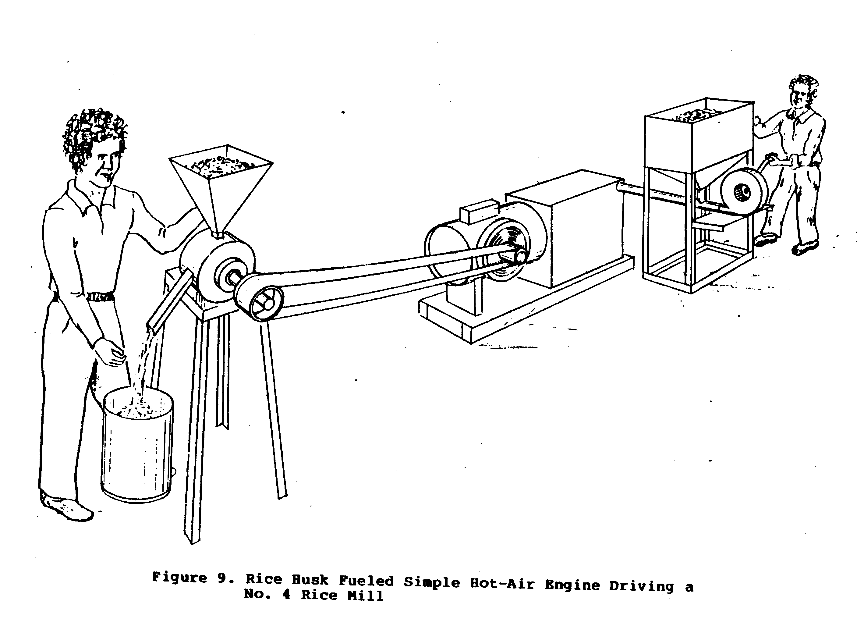
millng rice. It burns the rice husk produced by the mill it drives. Only a fraction of the husk produced by the mill is needed to fuel the engine, so ample amounts are left over for the engine to use while pumping irrigation water for the next rice crop. In this way, solar energy, in the form of biomass, is used as the primary energy input for the rice-growing process, and no outside fuel is necessary.
Solar Power
It is important to recognize that the Stirling engine is a high-temperature machine. It cannot run well on the low temperatures available from simple flat plate solar collectors. It must use a concentrating, sun-tracking solar collector. This device adds considerably to the cost and maintenance requirements of the system. Also, such a device does not make use of the diffuse component of solar energy, only the direct component. So hazy sun is not good enough. Bright, clear skies are needed before the concentrating collector will develop the high temperature necessary to operate the Stirling engine. For all these reasons, Stirling systems using concentrating, sun-tracking solar collectors will be much more expensive and will require more care in their operation than those using fuel as their heat source.
With those reservations in mind, it is right to point out that there are situations in which such solar-driven systems are worthy of consideration: where intense sunlight is the rule, where there is no biomass available and none derivable from the effects of the engine (as there would be eventually if the engine were irrigating a formerly desert area), and where the cost of the engine, collector, tracker, mount, and maintenance thereof is not prohibitive. Such a situation could exist where several kilowatts of electricity are needed, and the cost of photovoltaic systems is too high. It is likely that a solar electric system based on a free-piston Stirling engine will cost considerably less per watt delivered than will a photovoltaic system in the kilowatt range of power.
A cautionary note on solar Stirling systems: although the Stirling engine will be commercially available in one or two years, the concentrating collectors and their auxiliaries are still some distance away from production. For all these reasons, solar Stirling engine systems are likely to be much more costly than other systems except where nothing else is available, as might be the case in extreme desert zones.
More often than not, a direct solar system is less practical than one that uses biomass grown with the help of irrigation provided by the engine. By this means, land that would otherwise grow nothing could conceivably be made to produce food as well as fuel for the irrigating pump. Put simply, a field of weeds, harvested to be burned in the engine, is a much easier route to solar power than an elaborate optical system, mount, and tracker. And weeds, unlike the sun, do not hide behind clouds or go away at night.
FUEL EFFICIENCY AND POWER OUTPUT
The Stirling engine is likely to burn roughly 10 kilograms (kg) per kilowatt-hour (kWh) of biomass fuel, and 6 kg/kWh of coal. This is less than the rate of fuel consumption of small steam engines. Depending on how well an operator guides the machine, this burning rate can easily vary as much as 20 percent, up or down; with well-designed and well-attended engines, it could be as little as half as much.
The power output per unit of weight varies greatly with the design. Generally, it ranges from about .04 Kw/Kg for a simple crank-drive model to about .07 Kw/Kg for a commercial high-technology free-piston alternator engine.
IV. COMPARING THE ALTERNATIVES
The Stirling engine is capable of accepting heat from any source above about 400[degrees]C and converting part of the heat into useful work. This makes it capable of a wide variety of uses. Which of them are practical and worth consideration in comparison with the other sources of mechanical energy?
If conventional fuels and machines are available and satisfactory, it is probably not practical to consider replacing them with a Stirling engine. Only when petrol or diesel or clean gaseous fuels are scarce, expensive, or otherwise unattractive, and when the spark-ignition internal combustion engine or diesel engine is too short lived or too expensive to maintain or purchase, is it sensible to consider the application of the Stirling engine. If you consider introducing the Stirling engine, you must carefully evaluate its availability, proven performance characteristics, and economics, lest disappointment result.
COMPETITORS OF THE STIRLING ENGINE
The competition for the Stirling engine is the internal combustion engine, including the spark-ignition engine running on petrol, natural gas, alcohol, biogas, or producer gas, and the diesel engine running on diesel fuel, or a mixture of diesel and other gaseous or liquid fuels. The various solar cell devices as well as the steam engine are also considered to be competition for the Stirling engine.
The Stirling engine is most likely to be the best choice where the power required is between 100 watts and 20 kW, and some sort of biomass, coal, or peat is available as fuel. If gaseous or liquid fuel is readily available, a properly adapted internal combustion engine is likely to be cheaper, at least in the short run, although, depending on the relative cost of the fuels, the Stirling engine could be cheaper in the long run, due to lower maintenance and fuel costs.
Because the Stirling engine has been reintroduced only recently, it is hard to project the relative purchase costs of the several types of Stirling machines. It is likely that the Stirling engine will cost more than the spark-ignition internal combustion engine, and roughly the same as a slowspeed diesel engine of the same quality. But the Stirling engine is likely to have lower maintenance costs than either of these because of its great simplicity.
The Producer Gas Engine as a Competitor of the Stirling Engine
The producer gas engine runs on gas by means of a biomass-to-gas converter called a producer gas generator. The engine using the producer gas can be a converted petrol engine or a diesel engine using mainly producer gas but also requiring a small amount of diesel fuel as igniter for the producer gas. Since this combination can in fact do the same thing as a Stirling engine--that is, develop mechanical power from wood and other biomass--one is compelled to ask whether the Stirling engine has any advantage over the combination of producer gas generator and conventional internal combustion engine. In some cases, the answer is yes.
The Stirling engine has three advantages: (1) it can burn fuels with high ash content such as rice husks, which the producer gas system cannot; (2) since the combustion products do not enter the Stirling engine, they require no cleanup, in contrast to the producer gas internal combustion engine; and (3) the Stirling engine, in combination with a simple wrought fuel burner, is a much simpler and more maintenance-free system than the combination of producer gas generator, cleanup system, and internal combustion engine.
The Stirling engine overtakes the producer gas engine system if the fuel to be used is not of high quality, such as rice husks, and if the cost of maintaining the ignition system, injection system, lubrication, and other relatively delicate components of the internal combustion engine and the gas producer is a problem, as it so often is.
The Steam Engine as a Competitor of the Stirling Engine
It is logical to consider the steam engine as natural competition for the Stirling engine, as it in fact was at the time Rev. Stirling invented it. At that time the steam engine was the dominant power producer, whereas the Stirling engine was more fuel efficient, and much safer since it is almost impossible to cause a Stirling engine to blow up, and rather easy to do with a steam engine. Also at that time, the great disadvantage of the Stirling engine was the poor temperature resistance of the cast iron heater head.
Today, the situation is different. The steam engine has fallen into disuse, and the Stirling has leapt ahead in performance, life, and availability. With the use of series 300 stainless steel, a commonly available material, there is no longer the danger of heater head failure, at least below 700[degrees]C, which a normal solid fuel combuster produces on a running Stirling engine. And it is feasible to make the heater head of ceramic, especially in very low-pressure engines such as the simple free-piston water pumper.
Therefore, for low-power applications below several tens of kilowatts, the Stirling engine is likely to be much more fuel efficient, much easier to operate, much safer, and require much less maintenance. It is also likely to cost less, since the Stirling engine has so few parts and such simple ones in comparison to the steam engine. For example, the Stirling engine needs no valves, whereas the steam engine requires many, each one of which must work unfailingly in a hot, corrosive environment.
BIBLIOGRAPHY
Joshi, Deep; Seckler, David; and Jain, B.C. "Social Forestry, Wood Gasifiers and Lift Irrigation: Synergistic Relations Between Technology and Natural Resources in Rural India." January 1983, p. 1-16. (Mimeographed)
National Academy of Sciences. "Stirling Engines." Energy for Rural Development. Washington, D.C.: National Academy Press, 1981, pp. 149-158.
National Academy of Sciences. 'External Combustion Engines-- Rankine and Stirling Engines as Small-Scale Power Sources for Developing Countries." Energy for Rural Development. Washington, D.C.: National Academy Press, 1976, Appendix 4, pp. 246-269.
Ross, A. Stirling Cycle Engines. Phoenix, Arizona, 1977.
Urieli, I., and Berchowitz, D.M. Stirling Cycle Engine Analysis. Bristol, England: Adam Hilger, 1984.
Walker, G. Stirling Cycle Machines. Oxford, England: Oxford University Press, 1973.
Walker, G. Stirling Engines. Oxford, England: Oxford University Press, 1980.
Wood, J. Gary; Chagnot, Bruce J.; and Penswick, Lawrence B. "Design of a Low Pressure Air Engine for Third World Use." Paper presented at the 17th Annual Intersociety Energy Conference, Los Angeles, California, August 1982.