Published by VITA 1600 Wilson Boulevard, Suite 500 Arlington, Virginia 22209 USA Tel: 703-276-1800 . Fax: 703/243-1865 Internet: pr-info@vita.org
ISBN 0-86619-067-8
[C] 1980 Volunteers in Technical Assistance
I. WHAT IT IS AND WHAT IT IS USED FOR
II. DECISION FACTORS
- Applications
- Advantages
- Considerations
- Cost Estimate
III. MAKING THE DECISION AND FOLLOWING THROUGH
IV. PRE-CONSTRUCTION CONSIDERATIONS
- Undershot Waterwheel
- Overshot Waterwheel
- Site Selection
- Power Output
- Applications
- Records
- Materials and Tools
V. CONSTRUCTION
- Prepare the Diameter Section
- Prepare the Shrouds
- Prepare the Buckets
- Make the Wood Bearings
- Size of the Bearings
- Attach Metal or Wood Shaft to The Wheel
- Constructing Mountings and Tail Race
- Mounting the Wheel
- Mounting the Wheel - Vehicle Axle (Optional)
- Water Delivery to the Wheel
- Maintenance
VI. DICTIONARY OF TERMS
VII. FURTHER INFORMATION RESOURCES
VIII. CONVERSION TABLES
APPENDIX I. Site Analysis
APPENDIX II. Small Dam Construction
APPENDIX III. Pump Selection
APPENDIX IV. Calculating Bearing and Shaft Sizes
APPENDIX V. Decision Making Worksheet
APPENDIX VI. Record Keeping Worksheet
I. WHAT IT IS AND WHAT IT IS USED FOR
BACKGROUND
Improved use of water as a power source has potential for much of the developing world. There are few places where water is not available in quantities sufficient for power generation. Almost any flowing water--river, brook, or outlet of a lake or pona--can be put to work and will provide a steady source of energy. Fluctuations in the rate of flow usually are not too large and are spread out over time; water flow is far less subject to quick changes in energy potential and is available 24 hours a day.
The uses of energy from water are about the same as those for energy from the wind--electrical generation and mechanical power. Water-powered turbines attached to generators are used to generate electricity; waterwheels are generally used to power mechanical devices such as saws and machines for grinding grain.
Development of water power can be advantageous in communities where the cost of fossil fuels is high and access to electric transmission lines is limited.
POSSIBLE APPLICATIONS
The cost of employing water power can be high. As with any energy project, you must consider carefully all options. The
potential for power generation of the water source must be carefully matched with what it will power. For example, if a windmill and a waterwheel can be constructed to fill the same end use, the windmill may well require less time and money. On the other hand, it may be less reliable.
Using water power requires: 1) a constant and steady flow of water, and 2) sufficient "head" to run the waterwheel or turbine, if such is being used. "Head" is the distance the water falls before hitting the machine, be it waterwheel, turbine, or whatever. A higher head means more potential energy.
There is a greater amount of potential energy in a larger volume of water than in a smaller volume of water. The concepts of head and flow are important: some applications require a high head and less flow; some require a low head but a greater flow.
Many water power projects require building a dam to ensure both constant flow and sufficient head. It is not necessary to be an engineer to build a dam. There are many types of dams, some quite easy to build. But any dam causes changes in the stream and its surroundings, so it is best to consult someone having appropriate expertise in construction technique.
It is important to keep in mind that there can be substantial variation in the available flow of water, even with a dam to store the water. This is especially true in areas with seasonal rainfall and cyclical dry periods. Fortunately, in most areas these patterns are familiar.
Waterwheels have particularly high potential in areas where fluctuations in water flow are large and speed regulation is not practical. In such situations, waterwheels can be used to drive machinery which can take large fluctuations in rotation and speed. Waterwheels operate between 2 and 12 revolutions per minute and usually require gearing and belting (with related friction loss) to run most machines. (They are most useful for slow-speed) applications, e.g., flour mills, agricultural machinery, and some pumping operations.
A waterwheel, because of its rugged design, requires less care than a water turbine. It is self-cleaning, and therefore does not need to be protected from debris (leaves, grass, and stones).
Capital and labor costs can vary greatly with the way the power is used. For example, an undershot waterwheel in a small stream can be fairly easy and inexpensive to build. On the other hand, the set-up for generating electricity with a turbine can be complicated and costly. However, once a water power device is built and in operation, maintenance is simple and low in cost: it consists mainly of lubricating the machinery and keeping the dam in good condition. A well built and well situated water power installation can be expected to last for 20-25 years, given good maintenance and barring major catastrophes. This long life is certainly a factor to be figured into any cost calculation.
II. DECISION FACTORS
Applications: * water pumping.
* Low-speed machinery applications such as grist mills, oil presses, grinding machines, coffee hullers, threshers, water pumps, sugar cane presses, etc.
Advantages: * Can work over a range of water flow and head conditions.
* Very simple to build and operate.
* Virtually no maintenance required.
Considerations: * Not advisable for electrical generation or high-speed machinery applications.
* For optimum life expectancy water-resistant paints are needed.
COST ESTIMATE *
$100 to $300 (US, 1979) including materials and labor.
* Cost estimates serve only as a guide and will vary from country to country.
III. MAKING THE DECISION AND FOLLOWING THROUGH
When determining whether a project is worth the time, effort, and expense involved, consider social, cultural, and environmental factors as well as economic ones. What is the purpose of the effort? Who will benefit most? What will the consequences be if the effort is successful? And if it fails?
Having made an informed technology choice, it is important to keep good records. It is helpful from the beginning to keep data on needs, site selection, resource availability, construction progress, labor and materials costs, test findings, etc. The information may prove an important reference if existing plans and methods need to be altered. It can be helpful in pinpointing "what went wrong?" And, of course, it is important to share data with other people.
The technologies presented in this and the other manuals in the energy series have been tested carefully, and are actually used in many parts of the world. However, extensive and controlled field tests have not been conducted for many of them, even some of the most common ones. Even though we know that these technologies work well in some situations, it is important to gather specific information on why they perform properly in one place and not in another.
Well documented models of field activities provide important information for the development worker. It is obviously important for a development worker in Colombia to have the technical design for a machine built and used in Senegal. But it is even more important to have a full narrative about the machine that provides details on materials, labor, design changes, and so forth. This model can provide a useful frame of reference.
A reliable bank of such field information is now growing. It exists to help spread the word about these and other technologies, lessening the dependence of the developing world on expensive and finite energy resources.
A practical record keeping format can be found in Appendix VI.
IV. PRE-CONSTRUCTION CONSIDERATIONS
The two most common types of waterwheels are the undershot and the overshot versions.
UNDERSHOT WATERWHEEL
The undershot waterwheel (see Figure 1) should be used with a

head of 1.5 to 10 ft and flow rates from 10 to 100 cu ft per second. Wheel diameter should be three to four times the head ana is usually between 6 and 20 ft. Rotational speeds of the wheel are from 2-12 revolutions per minute; smaller wheels produce higher speeds. The wheel dips from 1-3 ft into the water. Efficiency is in the range of 60-75 percent.
OVERSHOT WATERWHEEL
The overshot waterwheel (see Figure 2) is used with heads of

10-30 ft and flow rates from 1-30 cu ft per second. Water is guided to the wheel through a wood or metal flume. A gate at the end of the flume controls the water flow to the wheel.
Wheel width can be fixed depending upon the amount of water available and the output needed. In addition, the width of the waterwheel must exceed the width of the flume by about 15cm (6") because the water expands as it leaves the flume. The efficiency of a well constructed overshot waterwheel can be 60-80 percent.
Overshot wheels are simple to construct, but they are large and they require a lot of time and material--as well as a sizeable workspace. Before beginning construction, it is a good idea to be sure facilities are or will be available for transporting the wheel and lifting it into place.
Even though an overshot wheel is simple to construct and does not require extreme care in cutting and fitting, it must be strong and sturdy. Its size alone makes it heavy, and in addition to its own weight, a wheel must support the weight of the water. The high torque delivered by the wheel requires a strong axle--a wooden beam or (depending on the size of the wheel) a car or tractor axle. Attention to these points will help prevent problems with maintenance.
Large waterwheels may be made much like a wagon wheel--with a rim attached to spokes. A smaller wheel may be made of a solid disc of wood or steel. Construction of a wheel involves the assembly of four basic parts: the disc or spokes of the wheel itself, the shrouds or sides of the buckets that hold the water, the buckets, and the mounting framework. Other parts are determined by the work the wheel is intended to do and may include a drive for a pump or grinding stone or a system of gears and pulleys for generating electricity.
Before a wheel is constructed, careful consideration should be given to the site of the wheel and the amount of water available. Because overshot wheels work by gravity, a relatively small flow of water is all that is needed for operation. Even so, this small flow must be directed into a flume or chute. Doing this often requires construction of a small dam.
The overshot waterwheel derives its name from the manner in which it is activated by the water. From a flume mounted above the wheel, water pours into buckets attached to the edge of the wheel and is discharged at the bottom. An overshot wheel operates by gravity: the water-filled buckets on the downward side of the wheel over-balance the empty buckets on the opposite side and keep the wheel moving slowly.
In general, overshot waterwheels are relatively efficient mechanically and are easily maintained. Their slow speed and high torque make them a good choice to operate such machinery as grist mills, coffee hullers, and certain water pumps. They may even be used for generating small amounts of electricity. Electrical generators require a series of speed multiplying devices that also multiply the problems of cost, construction, and maintenance.
Such a wheel should be located near, but not in, a stream or river. If a site on dry ground is chosen, the foundation may be constructed dry and the water led to the wheel and a tailrace excavated (see Figure 3). Efficiency of the wheel depends on

efficient and practical design considerations. The wheel must use the weight of the water through as much of the head as possible. The buckets should not spill or sling water until very near the tailwater.
The experience of the people at an isolated hospital in rural Malawi serves to illustrate many of the questions, both technical and cultural, that go into the development of a water power unit.
A failed cassava crop in the area led to the substitution of a new dietary staple--corn (maize). But the nearest mill for grinding the corn was a 49-kilometer (30-mile) walk away. Clearly something needed to be done to make milling facilities more accessible to the people.
A diesel-powered mill was too expensive and too difficult to maintain in that remote region. The river flowing past the hospital seemed to hold the promise of a power source, but, again, commercial water turbines proved too costly. Some kind of waterwheel seemed to provide an appropriate choice.
Development of the water power site involved the combined efforts of VITA and five VITA Volunteers, a missionary engineer in another area of Malawi, and OXFAM, another international development agency. Some data was also supplied by commercial milling firms. Much of the labor was volunteered by local people.
Correspondence between and among the participants involved choice of type of wheel, determining how to provide enough head to develop enough power to do the job, construction of the wheel, and selecting the proper burrs or grindstones.
Both VITA and OXFAM strongly recommended an overshot wheel for the reasons cited earlier: ease of construction and maintenance, reliability, and mechanical efficiency. With this comparison as a guide, the overshot wheel was chosen.
Power to run the grain mill required a head of about 427cm (14 ft, which would accommodate a wheel nearly 361cm (12 ft) across. The higher head necessary for the overshot wheel made it necessary to clear away additional boulders from the river bed, but this original investment in labor was more than returned by the increased efficiency of the wheel.
Additional correspondence (except for a couple of visits by the missionary engineer, the entire problem-solving process was handled by mail!) determined the precise shape, angle, size, and numbers of the buckets on the wheel. Also necessary was the design of a system of pulleys to transfer the power of the wheel to the milling operation.
As the wheel was constructed, attention was given to the grindstones. Granite found in the area seemed ideal, but proved to be too difficult for local stone cutters to deal with and yet not durable enough to be worth the time. Advice was sought from a millwright in New York and a variety of commercial milling firms. Ultimately a small commercial mill was chosen, with continued study going into preparing traditional stones.
In one of the last letters, hospital staff related that the wheel and mill were in place and operating. And from experience gained in this project they were already considering the possibility of constructing turbines to generate electricity.
SITE SELECTION
A careful analysis of the proposed site of the waterwheel is an important early step before construction begins. Whether it is a good idea to try to harness a stream depends on the reliability and quantity of the flow of water, the purpose for which power is desired, and the costs involved in the effort. It is necessary to look at all factors carefully. Does the stream flow all year round--even during dry seasons? How much water is available at the driest times? What will the power do--grind grain, generate electricity, pump water? These questions and others must be asked.
If a stream does not include a natural waterfall of sufficient height, a dam will have to be built to create the 'head' necessary to run the wheel. Head is the vertical distance which the water falls.
The site of the dam and wheel will affect the amount of head available. Water power can be very economical when a dam can be built into a small river with a relatively short (less than 100 ft) conduit (penstock for conducting water to the waterwheel). Development costs can be fairly high when such a dam and pipeline can provide a head of only 305cm (10 ft) or less. While a dam is not required if there is enough water to cover the intake of a pipe or channel at the head of the stream where the dam would be placed, a dam is often necessary to direct the water into the channel intake or to get a higher head than the stream naturally affords. This, of course, increases expense and time and serves as a very strong factor in determining the suitability of one site over another.
A thorough site analysis should include collection of the following data:
* Minimum flow in cubic feet or cubic meters per second.
* Maximum flow to be utilized.
* Available head in feet or meters.
* Site sketch with elevations, or topographic map with site sketched in.
* Water condition, whether clear, muddy, sandy, etc.
* Soil condition, the velocity of the water and the size of the ditch or channel for carrying it to the works depends on soil condition.
Measurements of stream flow should be taken during the season of lowest flow to guarantee full power at all times. Some investigation of the stream's history should be made to determine if there are perhaps regular cycles of drought during which the stream may dry up to the point of being unusable.
Appendices I and II of this manual contain detailed instructions for measuring flow, head, etc., and for building penstocks and dams. Consult these sections carefully for complete directions.
POWER OUTPUT
The amount of water available from the water source can be determined to assist in making the decision whether to build. Power may be expressed in terms of horsepower or kilowatts. One horsepower is equal to 0.7455 kilowatts; one kilowatt is about one and a third horsepower. The gross power, or full amount available from the water, is equal to the useful power plus the losses inherent in any power scheme. It is usually safe to assume that the net or useful power in small power installations will only be half of the available gross power due to water transmission losses and the gearing necessary to operate machinery.
* Gross power is determined by the following formula:
In English units:
Gross Power (horsepower) =
Minimum Water
Flow (cu ft/sec) X Gross Head (ft)
8.8
In Metric units:
Gross Power (metric horsepower) =
1,000 Flow (cu m/sec) X Head (m) ----- 75
* Net power available at the turbine shaft is:
In English units:
Net Power =
Minimum Water Flow
X Net Head(*) X Turbine Efficiency
8.8
In Metric Units:
Net Power =
Minimum Water Flow X Net Head(*) X Turbine Efficiency - 75/1,000
APPLICATIONS
While water pumping is an obvious use for the waterwheel, other machinery can be adapted to use the mechanical power output of the wheel. Almost any stationary machine which is currently hand-powered could be run by waterwheel power. Only in the case where the wheel and the machine are separated by long distances should there be any significant problem.
One problem which can occur when the machine is located some distance from the wheel is that the drive shaft of the machine will not easily be aligned with the waterwheel shaft. Alignment difficulties can be overcome simply and cheaply with old automobile rear axle assemblies, with the gears welded or jammed to give constant speed on both sides.
If the water supply to the wheel fluctuates, the speed of the wheel will vary. These speed variations are small and will generally not be of any consequence. If the variable speeds create problems, either a special constant velocity joint (as from the front wheel drive automobile) or two ordinary U joints must be used, each to compensate for the different motion of the other.
*The net head is obtained by deducting the energy losses from the gross head. These losses are discussed in Appendix I. When it is not known, a good assumption for waterwheel efficiency is 60 percent.
Flexible shafts are commercially available but are of limited torque-carrying capacity.
Solid shafts can transmit torque over considerable distance but require bearings for support and are expensive.
Generation of electricity is a possibility which will probably spring to the minds of most people reading this manual. There are waterwheel-driven electric generators in operation today, but the number of failed attempts testifies to the fact that it is not a simple, inexpensive project.
RECORDS
The need for power should be documented, and the measurements taken for the site analysis should be recorded. Costs of construction and operation can be compared to the benefit gained from the device to determine its real worth. (In making comparisons, don't forget to include the pond or lake created by the dam--it can be used to water livestock, raise fish, or irrigate fields.)
MATERIALS AND TOOLS
A simple, relatively economical 112cm (5 ft) wheel for pumping water can be made out of a disc of heavy plywood to which the buckets and shrouds are attached. Plywood is chosen because it is easy to use and relatively accessible; however, it does require special treatment to avoid deterioration and, in some places, may be quite expensive. The shaft of the wheel can be made either from metal or wood: the rear axle from an automobile may be used but, in most cases, axles are available only at great expense.
Lumber for shrouds, buckets, and rim reinforcement may be of almost any type available; hardwood is preferable. Ordinary wood saws, drills, and hammer are used in construction. Welding equipment is convenient if an automobile rear axle is being used. Materials for the dam and mounting structure should be chosen from whatever is at hand, based on the guidelines in this manual. While materials for the wheel may vary with what is available, they should include:
Materials
* 2cm thick plywood(*)--at least 112cm square.
* 6mm thick plywood(*)--122cm X 244cm sheet.
* 703cm total length of 3cm X 6cm boards to reinforce the edge of the disc.
* 703cm total length of 2cm X 30cm boards for the shrouds.
* 438cm total length of 2cm X 30cm boards for buckets.
* 703cm total length of 6mm X 20cm plywood* to reinforce the outside of the shrouds.
* 110cm long 5cm dia solid steel shaft or 9cm sq hardwood shaft. (Automobile rear axle is optional.)
* 5cm dia steel hubs (2) for steel shaft.
* 10 liters asphalt patching compound (or tar).
* Timbers and lumber for support structure as needed, nails, tin cans, bolts.
*Marine-grade plywood is preferred; waterproofed exterior-grade can be used.
Tools
* Protractor * Wood saw * Wood drill/bits * Hammer * Welding equipment (optional)
V. CONSTRUCTION
PREPARE THE DIAMETER SECTION
* Make a disc out of the 2cm thick plywood 112cm in dia. This is done using the meter stick.
* Nail one end of the ruler to the center of the plywood sheet.
* Measure 56cm from the nail and attach a pencil to the ruler.
* Scribe a circle and cut out disc with a wood saw (see Figure 4
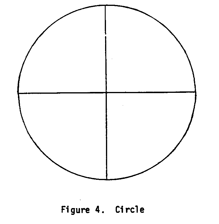
below).
* Divide the circle in half and then into quarters using a pencil and straight edge.
* Divide each quarter into thirds (30[degrees] intervals on protractor). The finished disc should look like Figure 5. The
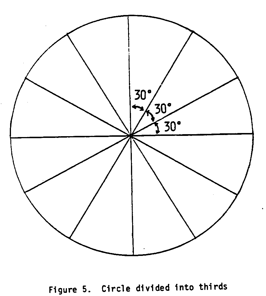
twelve reference lines will be used to guide the positioning of the buckets.
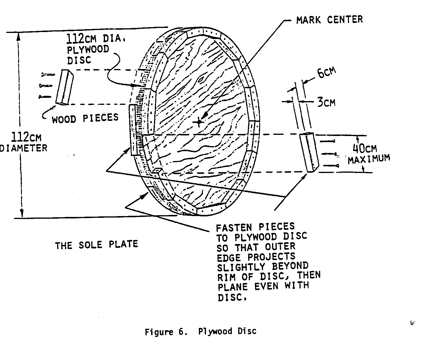
* Take 25-40cm lengths of 2cm X 3cm X 6cm lumber and nail them around the outside diameter of the wood disc on both sides so that the outer edge projects slightly beyond the rim of the disc (see Figure 6).
* Cut the 6mm thick X 122cm X 244cm plywood sheets into six strips 40.6cm wide X 122cm long.
* Bend and nail three of the strips around the disc so that they overhang equally on both sides.
* Bend and nail a second layer over the first, staggering the joints so as to give added strength and tightness (see Figure 7). These layers form what is called the sole plate
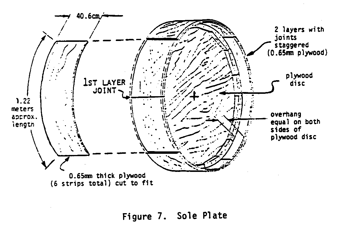
or backside of the buckets which will be attached later.
PREPARE THE SHROUDS
- Cut the shrouds, or sides, of the buckets from 2cm X 30cm wide boards. Nail one end of the meter stick to a piece of lumber. Measure 57.2cm from this nail. Drill 6mm hole and attach a pencil.
* Measure 20.5cm from this pencil, drill 6mm hole and attach another pencil. This becomes a compass for making the shrouds (see Figure 8).
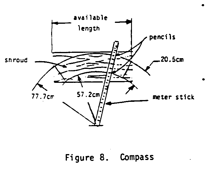
* Take 2cm X 30cm boards and scribe the outline of the shroud on, the wood. Cut out enough of the shrouds to fit around both sides of the disc. Shroud edges will have to be planed to fit.
* Nail the shroud pieces flush to the edge of the sole plate from the back side of the sole plate.
* Use the "compass" trace and cut out a second set of shrouds, or shroud covers, from 6mm thick plywood.
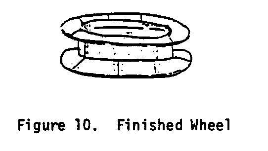
* Nail the plywood shroud covers on the outside of the first shrouds, with the joints overlapped (see Figure 9). Be sure

that the bottom edge of this second set of shrouds is flush with the bottom edge of the first layer of the sole plate.
* Fill in any cracks and seams with the asphalt patching compound or waterproof sealer. The finished wheel will look something like a cable spool (see Figure 10).
PREPARE THE BUCKETS
* Make the front sides of the twelve (12) buckets from hardwood boards 2cm X 30cm. The width of the front board will be 36.5cm.
* Make the bottom sections of the buckets from hardwood boards 2cm X 8cm. The length of each board will be 36.5cm.
* Cut the bottom of each 30cm section at a 24[degrees] angle from the horizontal and the top edge at a 45[degrees] angle from the horizontal as shown in Figure 11 before putting the two sections
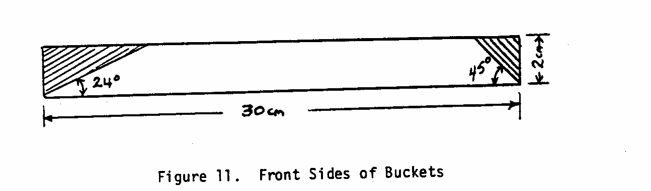
together.
* Nail the buckets together (see Figure 12). Each bucket
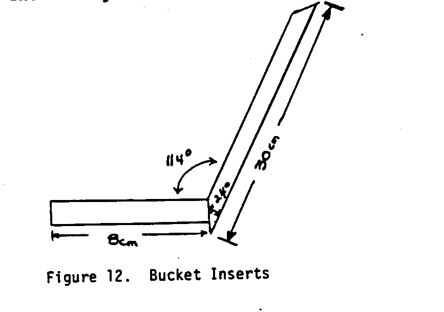
should have an inside angle of 114[degrees]. Place each bucket between the shrouds. Using the reference lines scribed on the disc earlier, match one bucket to each line as shown in Figure 13. The buckets can then be nailed
in place.
* Fill in all cracks with the asphalt patching compound.
MAKE THE WOOD BEARINGS
Bearings, for attaching the shaft to the wheel, will last longer if they are made from the hardest wood available locally. Generally, hardwoods are heavy and difficult to work. A local wood-craftsman should be able to provide information on the hardest woods. If there is doubt concerning the hardness or the self-lubricating quality of the wood that is going to be used in the bearings, thoroughly soaking the wood with oil will give longer life to the bearings.
Some advantages in using oil-soaked bearings are that they:
* Can be made from locally available materials.
* Can be made by local people with wood-working skills.
* Are easily assembled.
* Do not require further lubrication or maintenance in most cases.
* Are easily inspected and adjusted for wear.
* Can be repaired or replaced.
* Can provide a temporary solution to the repair of a more sophisticated production bearing.
The oiliness of the wood is important if the bearing is not going to be lubricated. Woods having good self-lubricating properties often are those which:
* Are easily polished.
* Do not react with acids (e.g., teak).
* Are difficult to impregnate with preservatives.
* Cannot be glued easily.
Usually the hardest wood is found in the main trunk just below the first branch. Wood freshly cut should be allowed to dry for two to three months to reduce moisture content. High moisture content will result in a reduction in hardness and will cause greater wear.
SIZE OF THE BEARING
The length of the wood bearings should be at least twice the shaft diameter. For example, for the 5cm dia axle or shaft of the waterwheel presented here, the bearing should be at least 10cm long. The thickness of the bearing material at any point should be at least the shaft diameter (i.e., for a 5cm dia shaft a block of wood 15cm X 15cm X 10cm long should be used).
Split block bearings (see Figure 14) should be used for the
waterwheel because it is a heavy piece of equipment and can cause a great deal of wear. These bearings are simple to make and replace.
The following steps outline the construction of a split-block bearing:
* Saw timber into an oblong block slightly larger than the finished bearing to allow for shrinkage.
* Bore a hole through the wood block the size of the axle/ shaft diameter.
* Cut block in half and clamp firmly together for drilling.
* Drill four 13mm or larger holes for attaching bearing to bearing foundation. After drilling, the two halves should be tied together to keep them in pairs.
* Impregnate the blocks with oil.
* Use an old 20-liter (5-gal) drum filled two-thirds full with used engine oil or vegetable oil.
* Place wood blocks in oil and keep them submerged by placing a brick on top (see Figure 15).
* Heat the oil until the moisture in the wood is turned into steam--this will give the oil an appearance of boiling rapidly.
* Maintain the heat until there are only single streams of small pin-sized bubbles rising to the oil's surface (see Figure 16).
This may take 30 minutes to 2 hours, or longer, depending on the moisture content of the wood. Soon after heating the bearing blocks in oil, many surface bubbles one-inch in diameter, made from a multitude of smaller bubbles, will appear on the surface.
As the moisture content of blocks is reduced, the surface bubbles will become smaller in size.
When the surface bubbles are formed from single streams of pin-sized bubbles, stop heating.
* Remove the heat source and leave the blocks in the oil to cool overnight. During this time the wood will absorb the oil.
BE VERY CAREFUL IN HANDLING THE CONTAINER OF HOT OIL.
* Remove wood blocks from the oil, reclamp and rebore the holes as necessary to compensate for shrinkage that may have taken place. The bearings are now ready to be used.
(Calculations for shaft and bearing sizes for larger waterwheels are provided in Appendix IV.)
ATTACH METAL OR WOOD SHAFT TO WHEEL
Metal Shaft
* Drill or cut out a 5cm dia round hole in the center of the wheel.
* Attach 5cm dia steel hubs as shown in Figure 17 using four
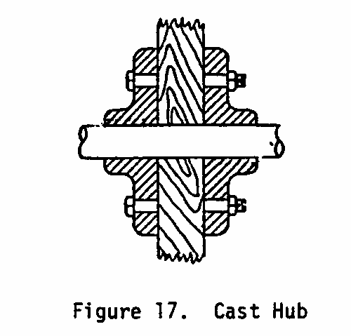
20mm X 15cm long bolts.
- Insert 110cm long metal shaft through the wheel center so that the shaft extends 30cm from one edge of the shroud and 38.2cm from the other edge (see Figure 18).
- Weld the shaft to the hub assembly on both sides as shown in Figure 19.
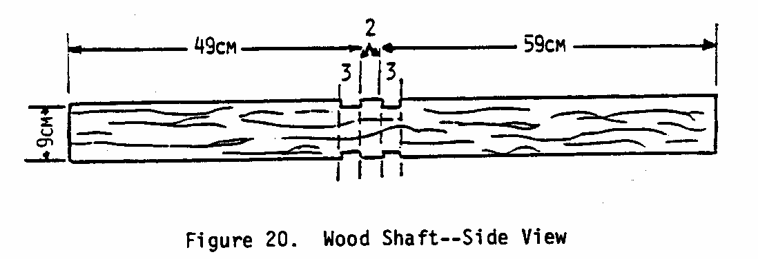
Wood Shaft
* Drill and carefully cut out a 9cm square hole in the center of the wheel.
* Measure 49cm from one end of the 110-cm long wood shaft and mark with a pencil. Measure 59cm from other end of the shaft and do the same. Turn the shaft over and repeat the procedure. There should be 2cm between the two marks.
* Cut grooves 3cm wide X 1cm deep on both sides of the shaft as shown below in Figure 20.
* Cut the 9cm shaft to 5cm dia only at the bearing (see Figure 21).
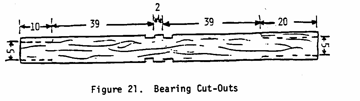
This step will take some time. A tin can 5cm in diam or the bearing itself can be used to gauge the cutting process. The finished shaft must be sanded and made as round and smooth as possible to prevent excessive or premature wear on the bearing.
* Insert wood shaft through wheel center so that the grooves show on either side of the wheel disc.
* Fit 3cm X 6cm X 15cm boards into the grooves so that they fit tightly. Tack each board to disc using nails to ensure a tight fit in the groove.
* Drill two 20mm dia holes through each 3cm X 6cm boards and disc. Insert 20mm dia X 10cm long bolts with washer through the disc and attach with washer and nut (see Figure 22 and Figure 23).
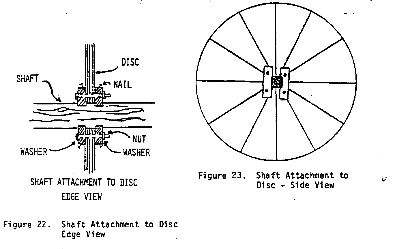
Remove nails.
* The wheel is now ready to be mounted.
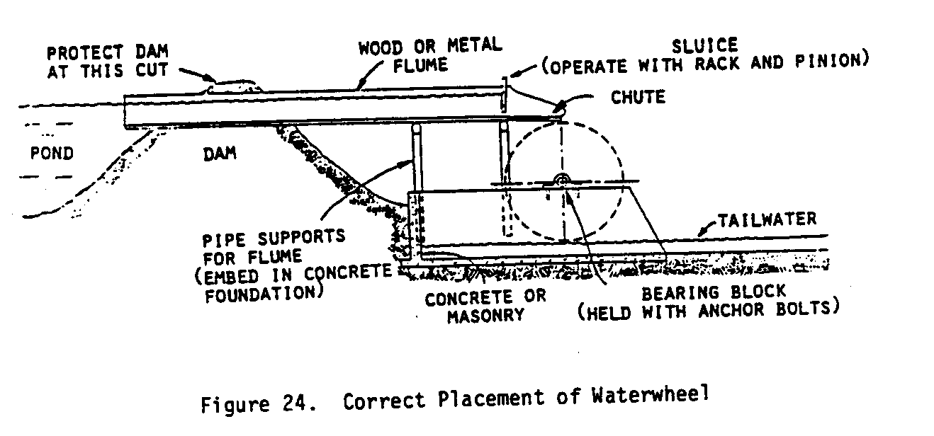
CONSTRUCTING MOUNTINGS AND TAILRACE
Stone or concrete pillars make the best mounting for the waterwheel. Heavy wood pilings or timber also have been used successfully. The primary determinant is, of course, local availability. Foundations should rest on a solid base--firm gravel or bedrock if possible to avoid settling. Large area footings will also help, and will prevent damage from stream erosion. If one end of the shaft is supported at the power plant building, this support should be as solid as the outer pillar.
Provision should be made for periodic adjustment in the alignment of the bearings in case one of the supports should settle or slide. Wood blocks can be used to mount the bearings, and these can be changed to adjust for any differences in elevation or placement. It is important that bearings and wheel shift be kept in perfect alignment at all times.
If the discharge or tailwater is not immediately removed from the vicinity of the wheel, the water will tend to back up on the wheel causing a serious loss of power. However, the drop necessary to remove this water should be kept at a minimum in order to lose as little as possible of the total available head.
The distance between the bottom of the wheel and the tailrace should be 20-30cm (4-6"). The tailrace or discharge channel should be smooth and evenly shaped down the stream bed below the wheel (see Figure 24).
MOUNTING THE WHEEL
Attach the bearings to the shaft and lift the wheel onto mounting pillars. Align the wheel vertically and horizontally through the use of wood blocks under the bearings. Once alignment has been done, drill through four holes in the bearing into the wood shim and mounting pillar.
Attach the bearings to the pillars using lag/anchor bolts in the case of concrete pillars or lag/anchor screws 13mm dia X 20cm long if wood pilings are used.
In mounting the shaft in the bearings, carefully avoid damage to the bearings and shaft. The shaft and bearings must be accurately aligned and solidly secured in place before the chute is assembled and located.
The wheel must be balanced in order to run smoothly, without uneven wear, or excess strain on the supports. When the wheel is secured on the mountings, it should turn easily and come to a smooth, even stop. If it is unbalanced, it will swing back and forth for a time before stopping. If this should occur, add a small weight (i.e., several nails or a bolt), at the top of the wheel when it is stopped. With care, enough weight can be added to balance the wheel perfectly.
MOUNTING THE WHEEL-VEHICLE AXLE (Optional)
Take a rear axle from a full-sized car and fix the differential gears so the two axles turn as one unit. You can jam these gears by welding so they don't operate. Cut off one axle and the axle housing to get rid of the brake assembly if you wish.
The other axle should be cleaned of brake parts to expose the hub and flange. You may have to knock the bolts out and get rid of the brake drum. The wooden disc of the waterwheel needs to have a hole made in its center to fit the car wheel hub closely. Also it should be drilled to match the old bolt holes and bolts installed with washers under the nuts.
Before mounting the wheel in place, have a base plate welded to the axle housing (see Figure 25). It should be on what is to be
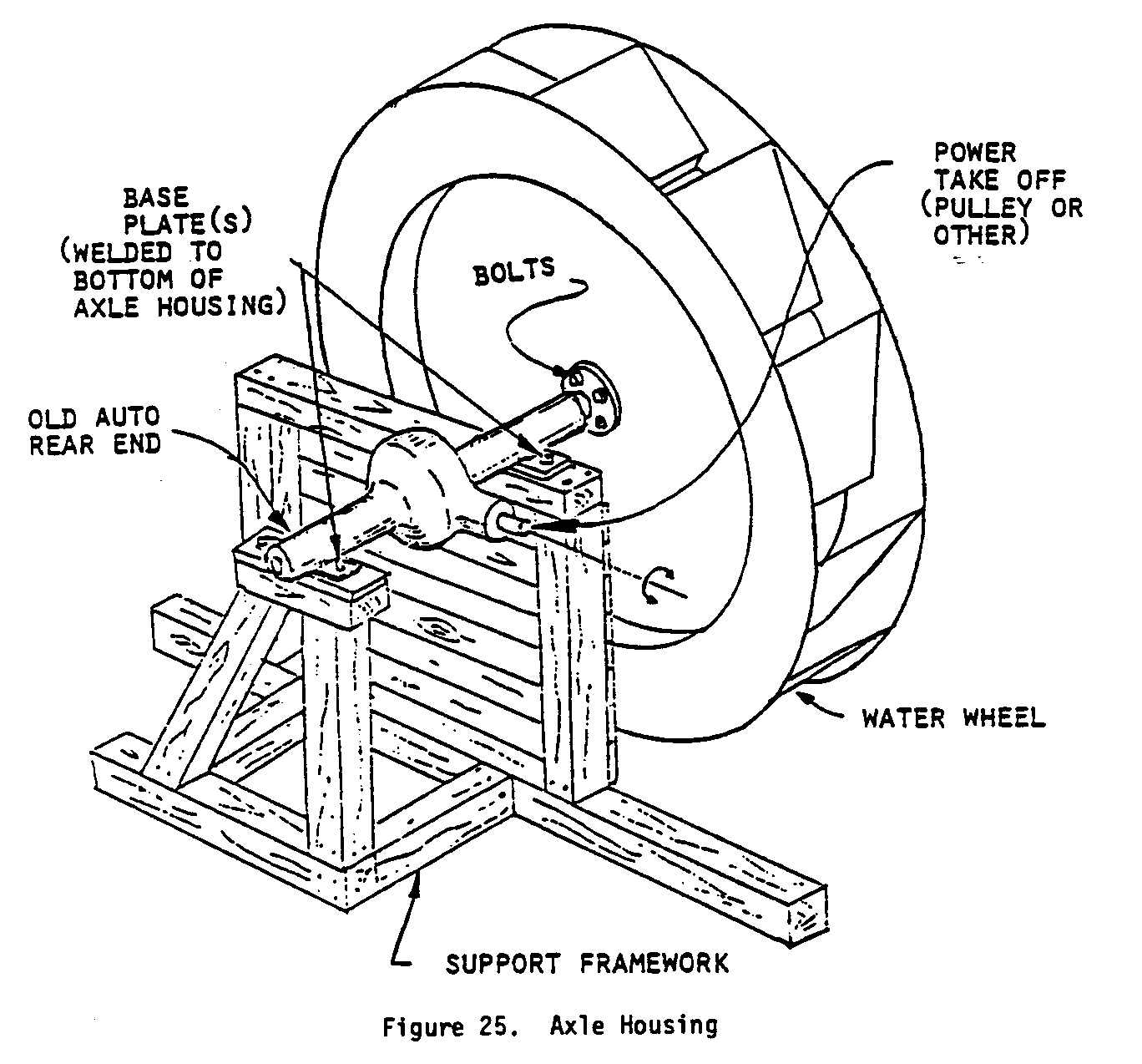
the underside, with two holes for 13mm lag screws. Make some kind of anchor to hold the opposite housing in place.
WATER DELIVERY TO WHEEL
For highest efficiency, water must be delivered to the wheel from a chute placed as close to the wheel as possible, and arranged so that the water falls into the buckets just after they reach upper dead center (see Figure 26). The relative
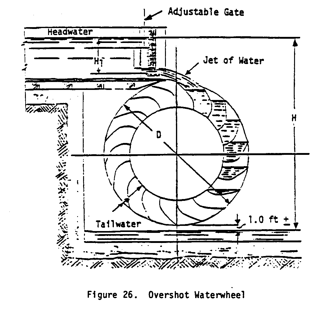
speed of the buckets and the water are very important.
The speed of the wheel will be reduced as the load it is driving increases. When large changes take place in the load, it is necessary to change the amount of water or the velocity of its approach to the wheel. This is done by a control gate located near the wheel, which can be raised or lowered easily and fixed at any position to give moderately accurate adjustment.
The delivery chute should run directly from the control gate to the waterwheel, and be as short as construction will permit (30cm-91cm long is best). A little slope is necessary to maintain the water velocity (1% or 30cm in every 3000cm will be satisfactory).
Flat-bottomed chutes are preferable. Even when water is delivered through a pipe, this should terminate in a control box and delivery made to the wheel through an open, flat-bottomed chute (see Figure 27). The tip of the chute
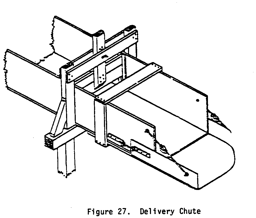
should be perfectly straight and level, and lined with sheet metal to prevent wear.
The chute should not be as wide as the waterwheel. This allows air to escape at the ends of the wheel as water enters the buckets. The width of the chute is usually 10-15cm (4-6") narrower than the width of the wheel. (In this case where the bucket width is 36.5cm the chute width will be 22-26cm.)
MAINTENANCE
All plywood parts must be waterproofed to keep them from deteriorating. Other wood parts may be painted or varnished for a protective coating. This helps extend the life of the wheel. wheel. Periodic repainting may be needed. Except for the plywood portions, the decision to paint can be made on purely economic grounds. If a very durable wood has been used initially, painting is a luxury. If a somewhat less durable species is used, painting is probably cheaper and easier than early replacement or repair of the wheel.
The only major maintenance problem is in bearing wear. Generous allowances have been made in bearing size but the bearings will still wear. When worn, the two halves can be interchanged; after further wear, the life of the bearing can be extended by planing off a small amount of wood from the matching faces. This will drop the wheel from its original position. Inserting wood or shimming under the bearing block with metal plates will compensate for this. Bearing replacement, when the block is completely worn through, is a simple matter.
Generally speaking, the bearing should be lubricated as needed. Oils/grease/vegetable oils applied periodically in small amounts will slow the wear rate.
VI. GLOSSARY
CATASTROPHE--A great and sudden disaster of calamity.
CYCLICAL DRY PERIODS--A periodically repeated sequence of environmental conditions where there is a lack of rainfall or water supply.
DIA (DIAMETER)--A straight line passing through the center of a circle and meeting at each end of the circumference.
EMBED--To fix firmly in a surrounding mass.
Head--Measurement of the difference in depth of a liquid at two given points (see Appendix I).
FLUME--A channel or chute for directing the flow of water.
FLUCTUATIONS--Irregular variations or instability of a regular process.
GRAVITY--The force of attraction that causes terrestial bodies to tend to fall toward the center of the earth.
RACK AND PINION--A device to
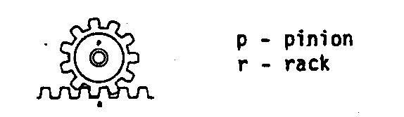
convert rotary motion to linear motion.
SHROUD--A device that covers, conceals, or protects something.
SLUICE--A man-made water channel with a valve or gate to regulate the flow.
SPROCKETS--Any of various toothlike projections arranged on a wheel rim to engage the links of a chain.
TELESCOPIC--Capable of being made longer or shorter by the sliding of overlapping tubular sections.
TOPOGRAPHIC MAP--A map showing the configuration of a place or region, usually by the use of contour lines.
VII. FURTHER INFORMATION RESOURCES
Cloudburst Press Ltd. Cloudburst manual, 1973. Cloudburst Press Ltd., Mayne Island, British Columbia, VON 2JO Canada. This manual, written by "homesteaders" in the Pacific Norethwest, has about 30 pages dealing with various aspects of water power. It covers measuring potential power, dams, and designs and construction of waterwheels. Highly readable and eminently practical, it is written by and for "do-it-yourselfers" working with limited resources. Also has excellent illustrations.
Hamm, Hans W. Low Cost Develoment of Small Water Power Sites, 1967. VITA, 3706 Rhode Island Avenue, Mount Rainier, Maryland 20822 USA. Written expressly to be used in developing areas, this manual contains basic information on measuring water power potential, building small dams, different types of turbines and waterwheels, and several necessary matehmatical tables. Also has some information on manufactured turbines available. A very useful book.
Monson, O.W., and Hill, Armin J. Overshot and Current Water Wheels, January 1942. Bulletin 398, Montana State College Agricultural and Experimental Station, Bozeman, Montana, USA. Written for the use of farmers and ranchers, this bulletin tells how to build "homemade" waterwheels from wood and scrap metal, as the emphasis is on simplicity and low cost. A good guide for building and installing overshot and undershot waterwheels, it is profusely illustrated and contains many practical hints for consideration.
Ovens, William G. A Design Manual for Waterwheels, 1975. VITA, 3706 Rhode Island Avenue, Mount Rainier, Maryland 20822 USA. The basic manual for waterwheel design and construction. Includes both theoretical and practical considerations, and is written to be used by people with a limited technical understanding. Also has a section on waterwheel applications as well as 16 highly useful tables and several schematic diagrams.
VIII. CONVERSION TABLES
UNITS OF LENGTH
1 Mile = 1760 Yards = 5280 Feet
1 Kilometer = 1000 Meters = 0.6214 Mile
1 Mile = 1.607 Kilometers
1 Foot = 0.3048 Meter
1 Meter = 3.2808 Feet = 39.37 Inches
1 Inch = 2.54 Centimeters
1 Centimeter = 0.3937 Inches
UNITS OF AREA
1 Square Mile = 640 Acres = 2.5899 Square Kilometers
1 Square Kilometer = 1,000,000 Square Meters = 0.3861 Square Mile
1 Acre = 43,560 Square Feet
1 Square Foot = 144 Square Inches = 0.0929 Square Meter
1 Square Inch = 6.452 Square Centimeters
1 Square Meter = 10.764 Square Feet
1 Square Centimeter = 0.155 Square Inch
UNITS OF VOLUME
1.0 Cubic Foot = 1728 Cubic Inches = 7.48 US Gallons
1.0 British Imperial Gallon = 1.2 US Gallons
1.0 Cubic Meter = 35.314 Cubic Feet = 264.2 US Gallons
1.0 Liter = 1000 Cubic Centimeters = 0.2642 US Gallons
1.0 Metric Ton = 1000 Kilograms = 2204.6 Pounds
1.0 Kilogram = 1000 Grams = 2.2046 Pounds
1.0 Short Ton = 2000 Pounds
UNITS OF PRESSURE
1.0 Pound per square inch = 144 Pound per square foot
1.0 Pound per square inch = 27.7 Inches of water*
1.0 Pound per square inch = 2.31 Feet of water*
1.0 Pound per square inch = 2.042 Inches of mercury*
1.0 Atmosphere = 14.7 Pounds per square inch (PSI)
1.0 Atmosphere = 33.95 Feet of water*
1.0 Foot of water = 0.433 PSI = 62.355 Pounds per square foot
1.0 Kilogram per square centimeter = 14.223 Pounds per square inch
1.0 Pound per square inch = 0.0703 Kilogram per square centimeter
UNITS OF POWER
1.0 Horsepower (English) = 746 Watt = 0.746 Kilowatt (KW)
1.0 Horsepower (English) = 550 Foot pounds per second
1.0 Horsepower (English) = 33,000 Foot pounds per minute
1.0 Kilowatt (KW) = 1000 Watt = 1.34 Horsepoer (HP) English
1.0 Horsepower (English) = 1.0139 Metric horsepower (cheval-vapeur)
1.0 Metric horsepower = 75 Meter X Kilogram/Second
1.0 Metric horsepower = 0.736 Kilowatt = 736 Watt *At 62 degrees Fahrenheit (16.6 degrees Celsius).
APPENDIX I
SITE ANALYSIS
This Appendix provides a guide to making the necessary calculations for a detailed site analysis.
Data Sheet
Measuring Gross Head
Measuring Flow
Measuring Head Losses
DATA SHEET
- Minimum flow of water available in cubic feet per second (or cubic meters per second).
- Maximum flow of water available in cubic feet per second (or cubic meters per second).
- Head or fall of water in feet (or meters).
- Length of pipe line in feet (or meters) needed to get the required head.
- Describe water condition (clear, muddy, sandy, acid).
- Describe soil condition (see Table 2).
- Minimum tailwater elevation in feet (or meters).
- Approximate area of pond above dam in acres (or square kilometers).
- Approximate depth of the pond in feet (or meters).
- Distance from power plant to where electricity will be used in feet (or meters).
- 11. Approximate distance from dam to power plant.
- 12. Minimum air temperature.
- 13. Maximum air temperature.
- 14. Estimate power to be used.
- 15. ATTACH SITE SKETCH WITH ELEVATIONS, OR TOPOGRAPHIC MAP WITH SITE SKETCHED IN.
The following questions cover information which, although not necessary in starting to plan a water power site, will usually be needed later. If it can possibly be given early in the project, this will save time later.
- Give the type, power and speed of the machinery to be driven and indicate whether direct, belt, or gear drive is desired or acceptable.
- For electric current, indicate whether direct current is acceptable or alternating current is required. Give the desired voltage, number of phases and frequency.
- Say whether manual flow regulation can be used (with DC and very small AC plants) or if regulation by an automatic governor is needed.
MEASURING GROSS HEAD
Method No. 1
- Equipment
a. Surveyor's leveling instrument--consists of a spirit level fastened parallel to a telescopic sight.
b. Scale--use wooden board approximately 12 ft in length.
- Procedure
a. Surveyor's level on a tripod is placed downstream from the power reservoir dam on which the headwater level is marked.
b. After taking a reading, the level is turned 180[degrees] in a horizontal circle. The scale is placed downstream from it at a suitable distance and a second reading is taken. This process is repeated until the tailwater level is reached.
Method No. 2
This method is fully reliable, but is more tedious than Method No. 1 and need only be used when a surveyor's level is not available.
- Equipment
a. Scale b. Board and wooden plug c. Ordinary carpenter's level
- Procedure
a. Place board horizontally at headwater level and place level on top of it for accurate leveling. At the downstream end of the horizontal board, the distance to a wooden peg set into the ground is measured with a scale.
b. The process is repeated step by step until the tailwater level is reached.
MEASURING FLOW
Flow measurements should take place at the season of lowest flow in order to guarantee full power at all times. Investigate the stream's flow history to determine the level of flow at both maximum and minimum. Often planners overlook the fact that the flow in one stream may be reduced below the minimum level required. Other streams or sources of power would then offer a better solution.
Method No. 1
For streams with a capacity of less than one cubic foot per second, build a temporary dam in the stream, or use a "swimming hole" created by a natural dam. Channel the water into a pipe and catch it in a bucket of known capacity. Determine the stream flow by measuring the time it takes to fill the bucket.
Stream flow (cubic ft/sec) = Volume of bucket (cubic ft)
Filling time (seconds)
Method No. 2
For streams with a capacity of more than 1 cu ft per second, the weir method can be used. The weir is made from boards, logs, or scrap lumber. Cut a rectangular opening in the center. Seal the seams of the boards and the sides built into the banks with clay or sod to prevent leakage. Saw the edges of the opening on a slant to produce sharp edges ont he upstream side. A small pond is formed upstream from the weir. When there is no leakage and all water is flowing through the weir opening, (1) place a board across the stream and (2) place another narrow board at right angles to the first, as shown below.
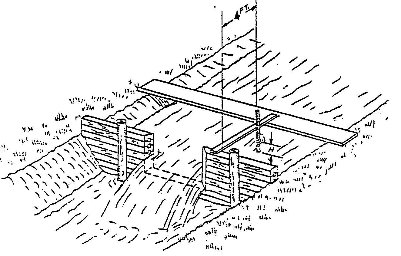
Use a carpenter's level to be sure the second board is level.
Measure the depth of the water above the bottom edge of the weir with the help of a stick on which a scale has been marked. <see figure 5> Determine the flow from Table 1 on page 56.
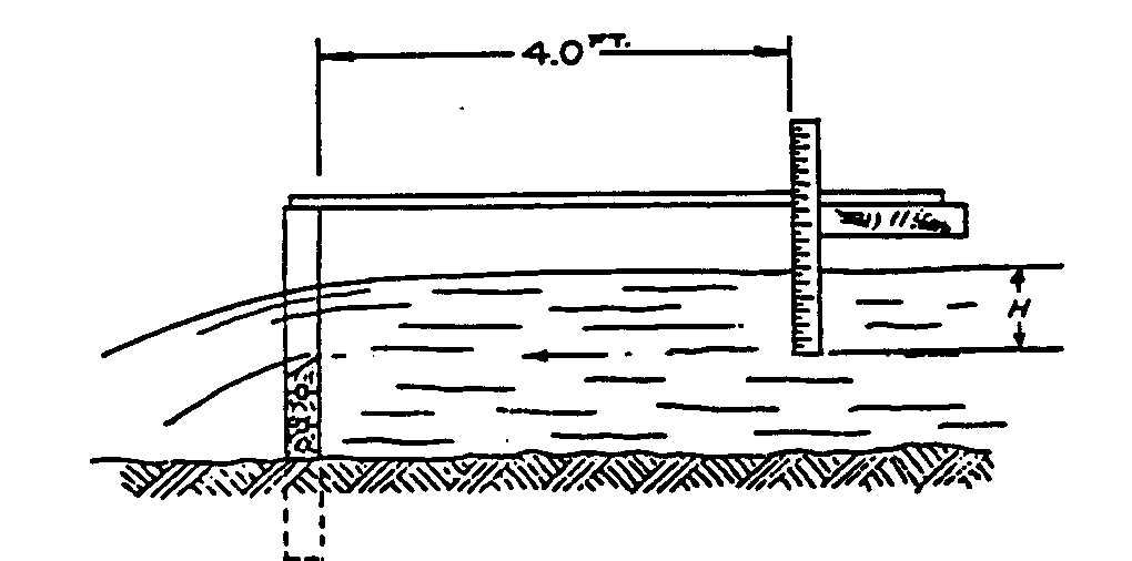
Table I FLOW VALUE (Cubic Feet/Second)
Weir Width
Overflow Height 3 feet 4 feet 5 feet 6 feet 7 feet 8 feet 9 feet
1.0 inch 0.24 0.32 0.40 0.48 0.56 0.64 0.72 2.0 inches 0.67 0.89 1.06 1.34 1.56 1.80 2.00 4.0 inches 1.90 2.50 3.20 3.80 4.50 5.00 5.70 6.0 inches 3.50 4.70 5.90 7.00 8.20 9.40 10.50 8.0 inches 5.40 7.30 9.00 10.80 12.40 14.60 16.20 10.0 inches 7.60 10.00 12.70 15.20 17.70 20.00 22.80 12.0 inches 10.00 13.30 16.70 20.00 23.30 26.60 30.00
Method No. 3
The float method is used for larger streams. <see figure 6> Although it is not
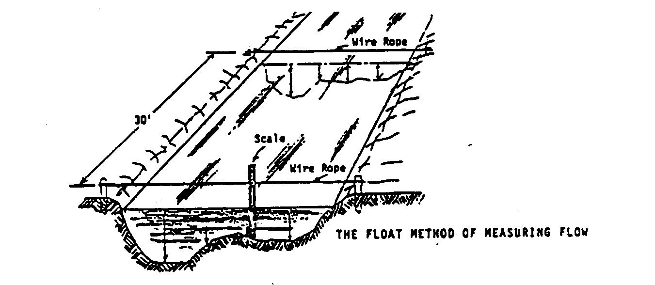
as accurate as the previous two methods, it is adequate for practical purposes. Choose a point in the stream where the bed is smooth and the cross section is fairly uniform for a length of at least 30 ft. Measure water velocity by throwing pieces of wood into the water and measuring the time of travel between two fixed points, 30 ft or more apart. Erect posts on each bank at these points. Connect the two upstream posts by a level wire rope (use a carpenter's level). Follow the same procedure with the downstream posts. Divide the stream into equal sections along the wires and measure the water depth for each section. In this way, the cross-sectional area of the stream is determined. use the following formula to calculate the flow:
Stream Flow (cu ft/sec) = Average cross-sectional flow area (sq ft) X velocity (ft/sec)
MEASURING HEAD LOSSES
"Net Power" is a function of the "Net Head." The "Net Head" is the "Gross Head" less the "Head Losses." The illustration below shows a typical small water power installation. The head losses are the open-channel losses plus the friction loss from flow through the penstock. <see figure 7>

A TYPICAL INSTALLATION FOR A LOW-OUTPUT WATER POWER PLANT
1. River 2. Dam with Spillway 3. Intake to Headrace 4. Headrace 5. Intake to Turbine Penstock 6. Trashrack 7. Overflow of Headrace 8. Penstock 9. Turbine Inlet Valve 10. Water Turbine 11. Electric Generator 12. Tailrace
Open Channel Bead Losses
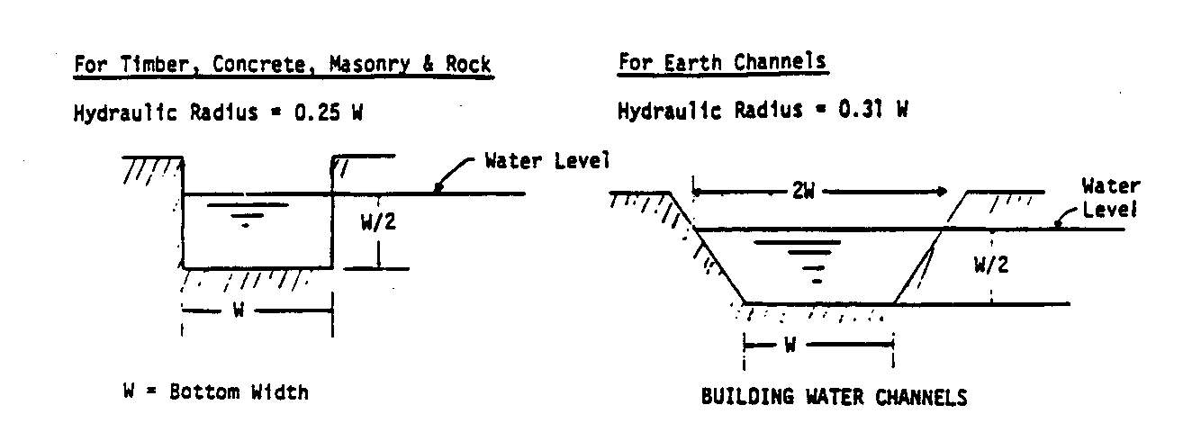
The headrace and the tailrace in the illustration above are open channels for transporting water at low velocities. The walls of channels made of timber, masonry, concrete, or rock, should be perpendicular. Design them so that the water level height is one-half of the width. Earth walls should be built at a 45[degrees] angle. Design them so that the water level height is one-half of the channel width at the bottom. At the water level the width is twice that of the bottom. <see figure 8>
The head loss in open channels is given in the nomograph. The friction effect of the material of construction is called "N". Various values of "N" and the maximum water velocity, below which the walls of a channel will not erode are given.
TABLE II
Maximum Allowable Water Velocity Material of Channel Wall (feet/second) Value of "n"
Fine grained sand 0.6 0.030 Course sand 1.2 0.030 Small stones 2.4 0.030 Coarse stones 4.0 0.030 Rock 25.0 (Smooth) 0.033 (Jagged) 0.045 Concrete with sandy water 10.0 0.016 Concrete with clean water 20.0 0.016 Sandy loam, 40% clay 1.8 0.030 Loamy soil, 65% clay 3.0 0.030 Clay loam, 85% clay 4.8 0.030 Soil loam, 95% clay 6.2 0.030 100% clay 7.3 0.030 Wood 0.015 Earth bottom with rubble sides 0.033
The hydraulic radius is equal to a quarter of the channel width, except for earth-walled channels where it is 0.31 times the width at the bottom.
To use the nomograph, a straight line is drawn from the value of "n" through the flow velocity to the reference line. The point on the reference line is connected to the hydraulic radius and this line is extended to the head-loss scale which also determines the required slope of the channel.
Using a Nomograph
After carefully determining the water power site capabilities in terms of water flow and head, the nomograph is used to
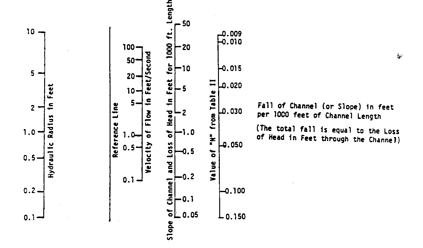
determine:
* The width/depth of the channel needed to bring the water to the spot/location of the water turbine.
* The amount of head lost in doing this.
To use the graph, draw a straight line from the value of "n" through the flow velocity through the reference line tending to the hydraulic radius scale. The hydraulic radius is one-quarter (0.25) or (0.31) the width of the channel that needs to be built. In the case where "n" is 0.030, for example, and water flow is 1.5 cubic feet/second, the hydraulic radius is 0.5 feet or 6 inches. If you are building a timber, concrete, masonry, or rock channel, the total width of the channel would be 6 inches times 0.25, or 2 feet with a depth of at least 1 foot. If the channel is made of earth, the bottom width of the channel would be 6 times 0.31, or 19.5 inches, with a depth of at least 9.75 inches and top width of 39 inches.
Suppose, however, that water flow is 4 cubic feet/second. Using the graph, <see graph> the optimum hydraulic radius would be approximately
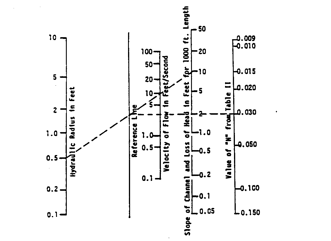
2 feet--or for a wood channel, a width of 8 feet. Building a wood channel of this dimension would be prohibitively expensive.
However, a smaller channel can be built by sacrificing some water head. For example, you could build a channel with a hydraulic radius of 0.5 feet or 6 inches. To determine the amount of head that will be lost, draw a straight line from the value of "n" through the flow velocity of 4 [feet.sup.3]/second to the reference line. Now draw a straight line from the hydraulic radius scale of 0.5 feet through the point on the reference line extending this to the head-loss scale which will determine the slope of the channel. In this case about 10 feet of head will be lost per thousand feet of channel. If the channel is 100 feet long, the loss would only be 1.0 feet--if 50 feet long, 0.5 feet, and so forth.
Pipe Bead Loss and Penstock Intake
The trashrack consists of a number of vertical bars welded to an angle iron at the top and a bar at the bottom (see Figure below).
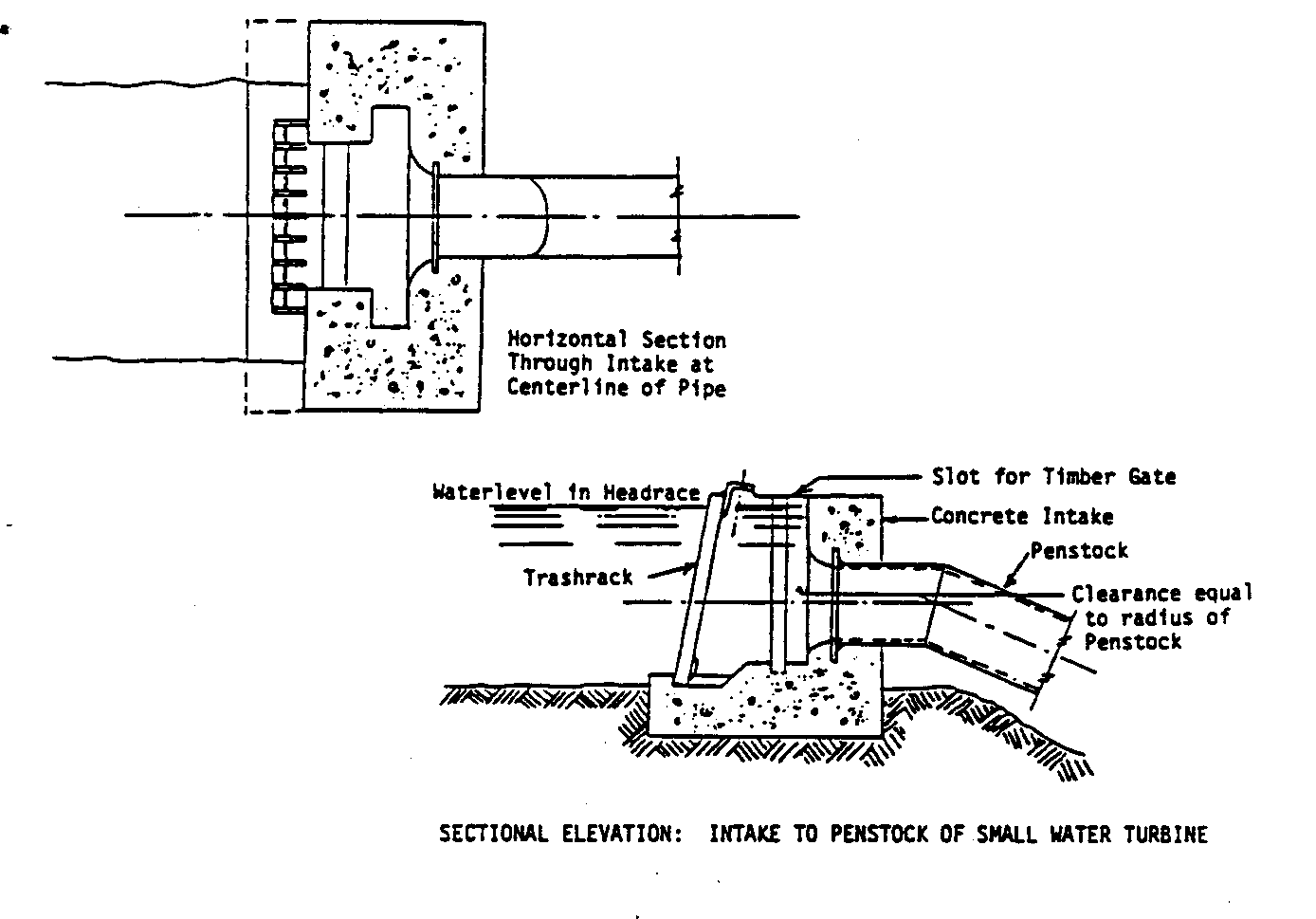
The vertical bars must be spaced so that the teeth of a rake can penetrate the rack for removing leaves, grass, and trash which might clog up the intake. Such a trashrack can easily be manufactured in the field or in a small welding shop. Downstream from the trashrack, a slot is provided in the concrete into which a timber gate can be inserted for shutting off the flow of water to the turbine.
The penstock can be constructed from commercial pipe. The pipe must be large enough to keep the head loss small. The required pipe size is determined from the nomograph. A straight line
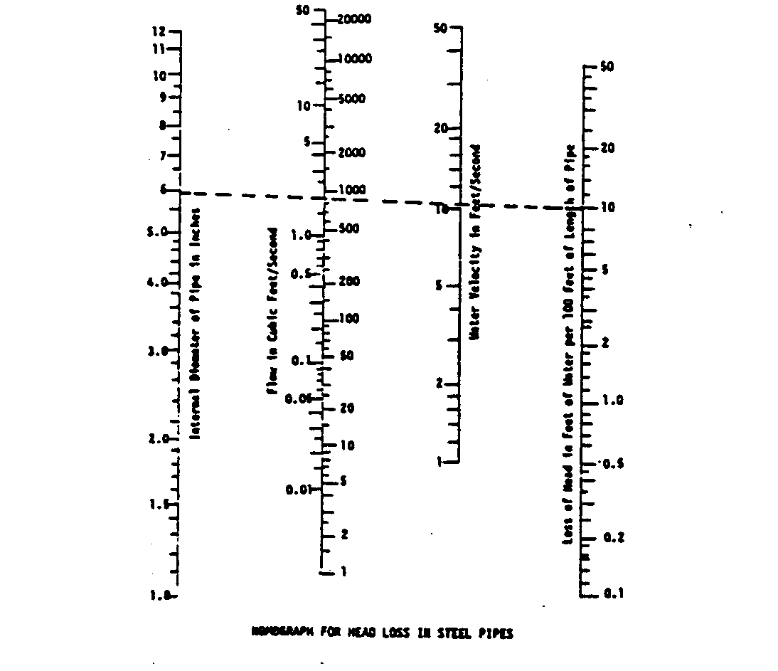
drawn through the water velocity and flow rate scales gives the required pipe size and pipe head loss. Head loss is given for a 100-foot pipe length. For longer or shorter penstocks, the actual head loss is the head loss from the chart multiplied by the actual length divided by 100. If commercial pipe is too expensive, it is possible to make pipe from native material; for example, concrete and ceramic pipe, or hollowed logs. The choice of pipe material and the method of making the pipe depend on the cost and availability of labor and the availability of material.
APPENDIX II
SMALL DAM CONSTRUCTION
This appendix is not designed to be exhaustive; it is meant to provide background and perspective for thinking about and planning dam efforts. While dam construction projects can range from the simple to the complex, it is always best to consult an expert, or even several; for example, engineers for their construction savvy and an environmentalist or concerned agriculturalist for a view of the impact of damming.
Introduction to:
Earth Dams
Crib Dams
Concrete and Masonry Dams
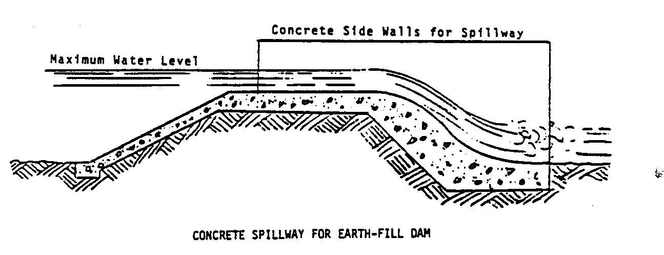
EARTH DAMS
An earth dam may be desirable where concrete is expensive and timber scarce. It must be provided with a separate spillway of sufficient size to carry off excess water because water can never be allowed to flow ovewr the crest of an earth dam. Still water is held satisfactorily by earth but moving water is not. The earth will be worn away and the dam destroyed.
The spillway must be lined with boards or concrete to prevent seepage and erosion. The crest of the dam may be just wide enough for a footpath or may be wide enough for a roadway, with a bridge placed across the spillway.
The big problem in earth-dam construction is in places where the dam rests on solid rock. It is hard to keep the water from seeping between the dam and the earth and finally undermining the dam.
One way of preventing seepage is to blast and clean out a series of ditches, or keys, in the rock, with each ditch about a foot deep and two feet wide extending under the length of the dam. Each ditch should be filled with three or four inches of wet clay compacted by stamping it. More layers of wet clay can then be added and the compacting process repeated each time until the clay is several inches higher than bedrock.
The upstream half of the dam should be of clay or heavy clay soil, which compacts well and is impervious to water. The downstream side should consist of lighter and more porous soil which drains quickly and thus makes the dam more stable than if it were made entirely of clay.
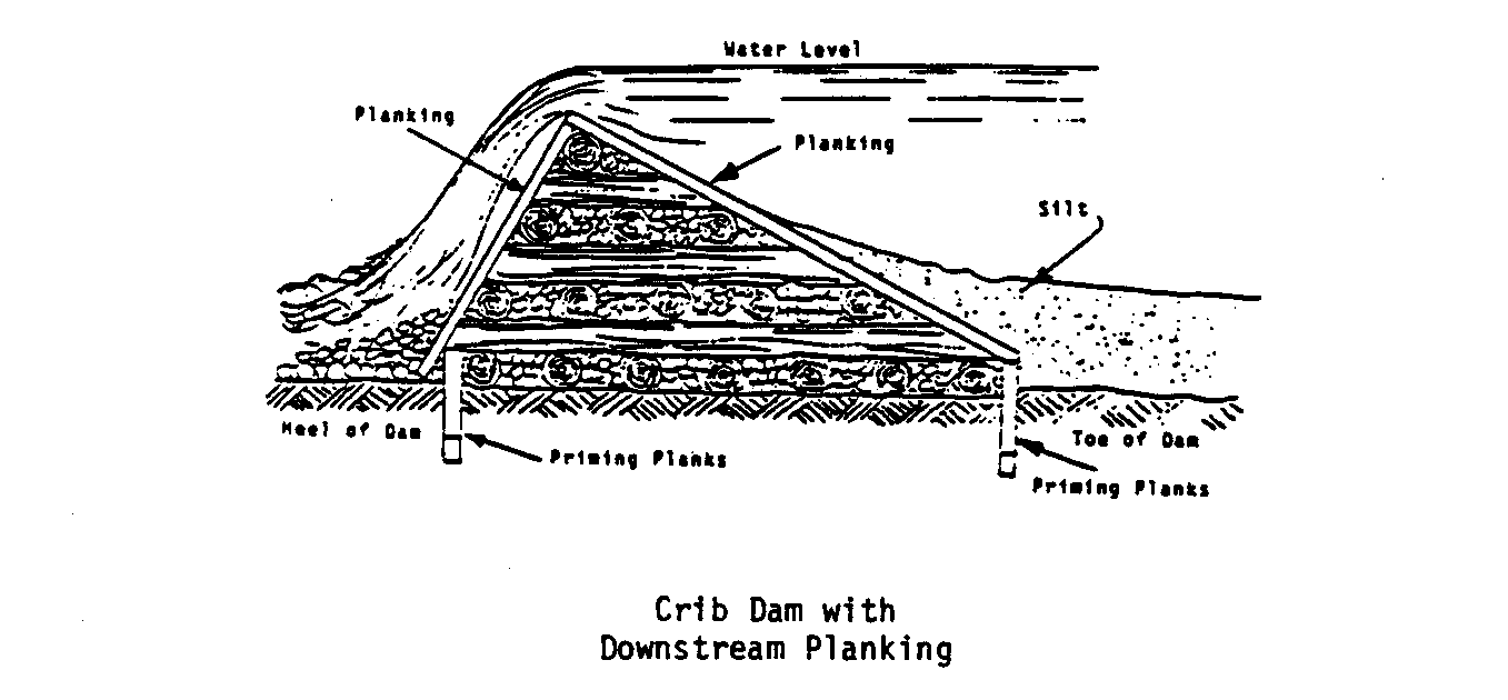
CRIB DAMS
The crib dam is very economical where lumber is easily available: it requires only rough tree trunks, cut planking, and stones. Four- to six-inch tree trunks are placed 2-3 feet apart and spiked to others placed across them at right angles. Stones fill the spaces between timbers. The upstream side (face) of the dam, and sometimes the downstream side, is covered with planks. The face is sealed with clay to prevent leakage. Downstream planks are used as an apron to guide the water which overflows the dam back into the stream bed. The dam itself serves as a spillway in this case. The water coming over the apron falls rapidly. Prevent erosion by lining the bed below with stones. The apron consists of a series of steps for slowing the water gradually.
Crib dams must be embedded well into the embankments and packed with impervious material such as clay or heavy earth and stones in order to anchor them and to prevent leakage. At the heel, as well as at the toe of crib dams, longitudinal rows of planks are driven into the stream bed. These are priming planks which prevent water from seeping under the dam, and they also anchor it.
If the dam rests on rock, priming planks cannot and need not be driven; but where the dam does not rest on rock they make it more stable and watertight. These priming planks should be driven as deep as possible and then spiked to the timber of the crib dam.
The lower ends of the priming planks are pointed as shown in the Figure on page 69 and must be placed one after the other as
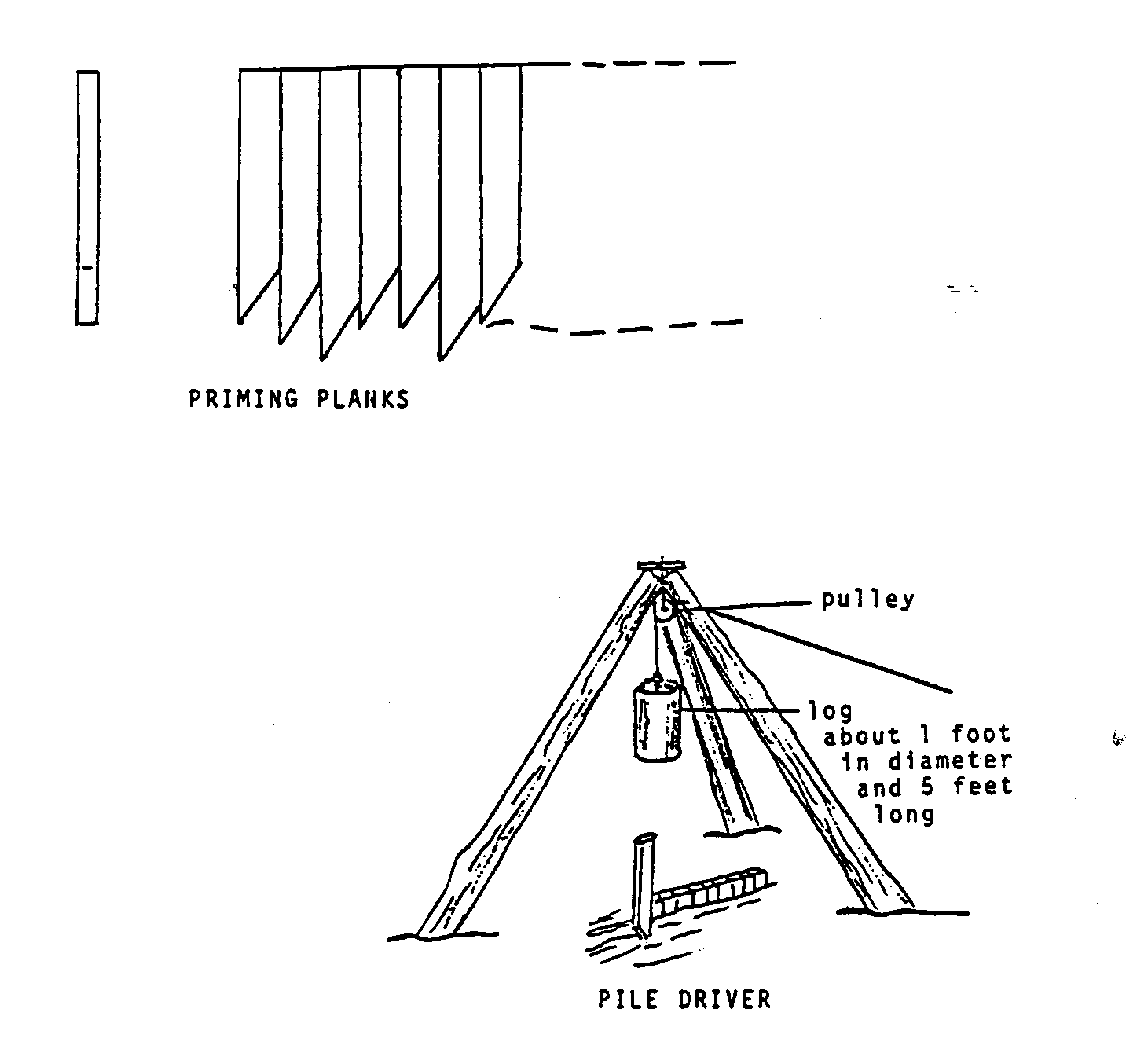
shown. Thus each successive plank is forced, by the act of driving it closer against the preceding plank, resulting in a solid wall. Any rough lumber may be used. Chestnut and oak are considered to be the best material. The lumber must be free from sap, and its size should be approximately 2" X 6".
In order to drive the priming planks, considerable force may be required. A simple pile driver will serve the purpose. The Figure below shows an excellent example of a pile driver.
CONCRETE AND MASONRY DAMS
Concrete and masonry dams more than 12 feet high should not be built without the advice of an engineer with experience in this field. Dams require knowledge of the soil condition and bearing capacity as well as of the structure itself.
A stone dam can also serve as a spillway. It can be up to 10
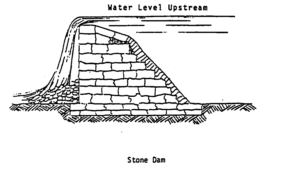
feet in height. It is made of rough stones. The layers should be bound by concrete. The dam must be built down to a solid and permanent footing to prevent leakage and shifting. The base of the dam should have the same dimensions as its height to give it stability.
Small concrete dams should have a base with a thickness 50
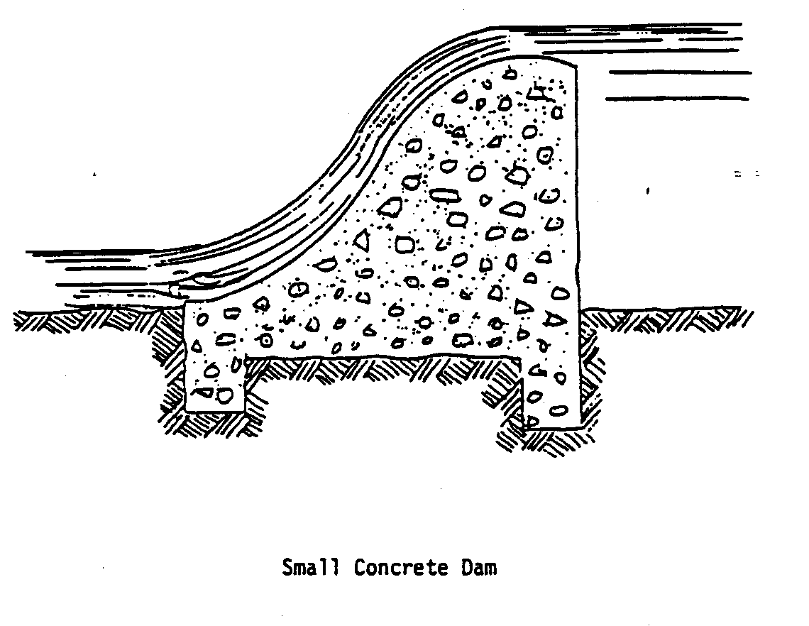
percent greater than height. The apron is designed to turn the flow slightly upwards to dissipate the energy of the water and protect the downstream bed from erosion.
APPENDIX III
PUMP SELECTION
Design for a Simple Pump
PUMP SELECTION
One choice for a water-powered pump is a positive displacement pump. Such pumps are called by various names: bucket pump, lift pump, piston pump, windmill pump, and occasionally even simply by brand name, such as "Rocket" pump. Numerous models are available commercially and vary in cost from a few dollars for small capacity pumps to several hundred for high capacity, high head, durable, well manufactured units. However, pumps can be manufactured at low cost in the simplest of workshops.
One single acting pump attached to the wheel will cause speed surges on the wheel because actual pumping takes place only half the time, while the other half is spent filling the cylinder. During the filling stage, considerably less wheel torque is required than when pumping is being done. The speed surge can be partially overcome by using:
* Two single-acting pumps 180[degrees] out of phase so that one of the

pumps is always doing useful work.
* A double-acting pump which
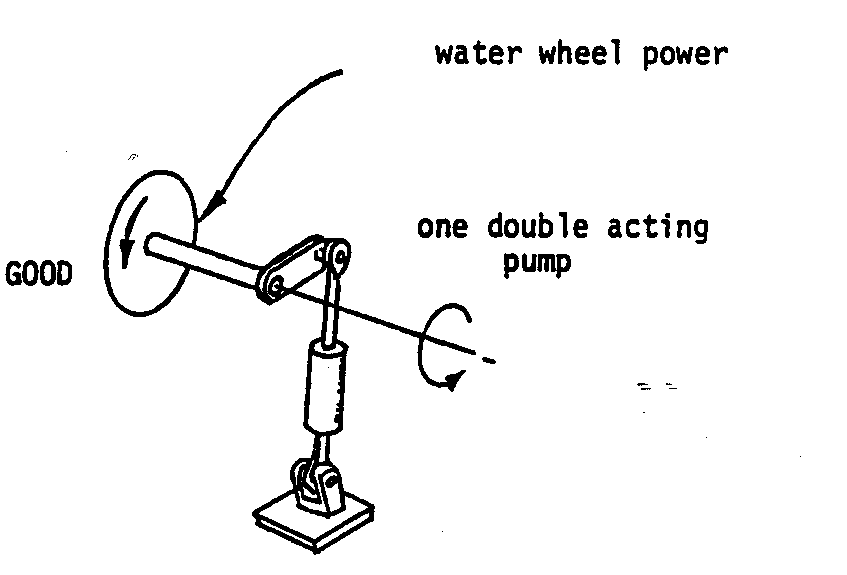
has the same effect as the one above but is built in one unit; or
* best of all, two double-acting
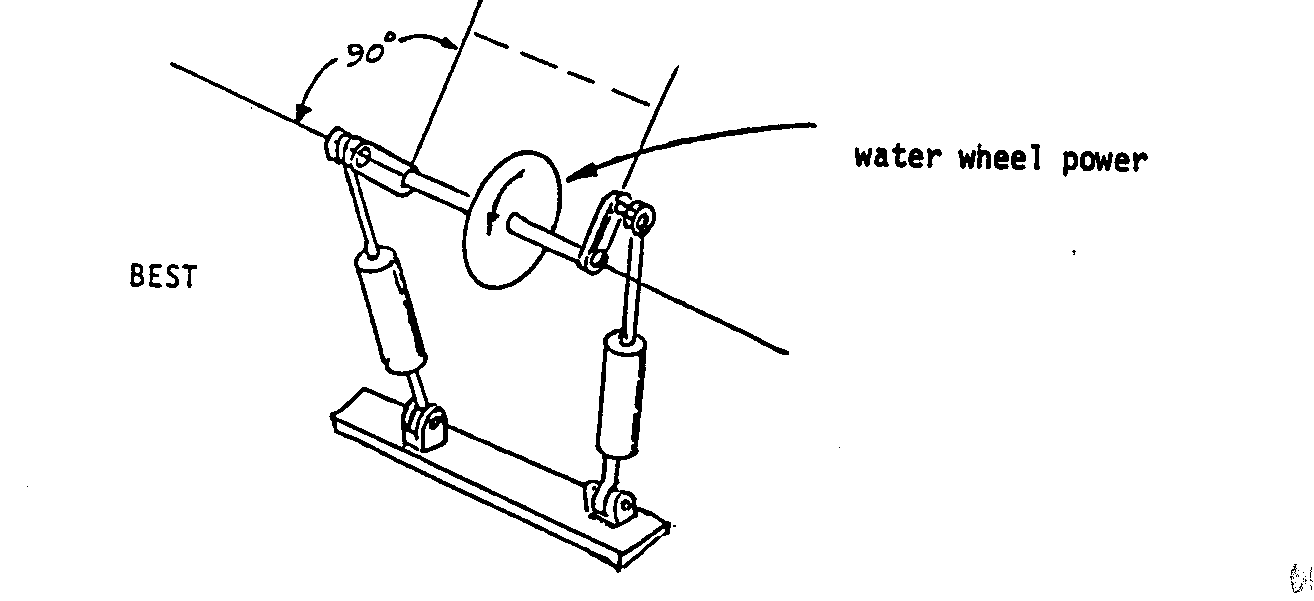
pumps 90[degrees] out of phase.
Use of multiple simple pumps improves the overall efficiency of the system. (In general, one unit can be attached easily to a crank at each end of the wheel shaft.)
Table 1. Quantities of Water Pumped Per Stroke for Single-Acting Pumps of Various Bore and Stroke Sizes (Imperial Gallons)
Stroke (in.)
Bore (in.) 2-1/4 4 6 8 10 12
1-1/4 .009 .016 .023 .032 .040 .049 1-1/2 .013 .023 .035 .045 .057 .069 2 .023 .040 .062 .082 .102 .122 2-1/2 .035 .064 .095 .127 .159 .191 3 .052 .092 .139 .184 .230 .278 3-1/2 .070 .125 .187 .248 .312 .276 4 .092 .163 .245 .227 .410 .489 5 .143 .255 .382 .510 .638 .765
DESIGN FOR A SIMPLE PUMP
An Easily Constructed Piston Pump
This pump <see figure> was designed by P. Brown
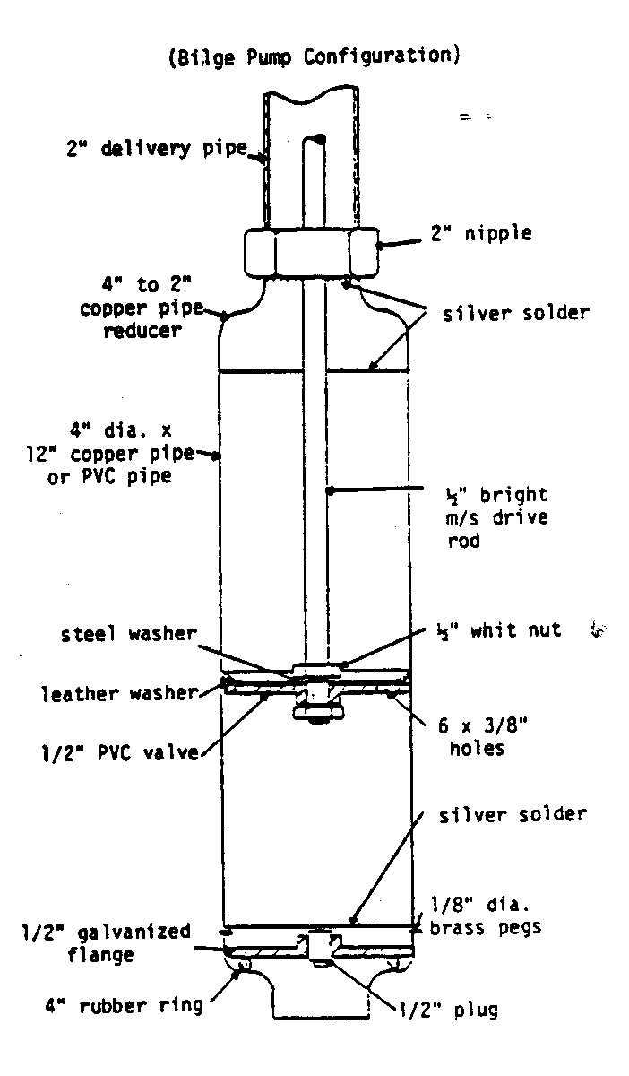
(of the Mechanical Engineering Workshop at the Papua New Guinea University of Technology) with a view to manufacture in Papua New Guinea. Consequently the pump can be built using a minimum of workshop equipment--most parts are standard pipe fittings available from any plumbing supplier.
A PVC pipe can be used in place of copper pipe. This eliminates the need for a pipe reducer. The PVC pipe can have a uniform diameter throughout.
To avoid having to bore and hone a pump cylinder, a length of copper or PVC pipe is used. If care is taken to select an undamaged length of pipe and to see that the pipe is not damaged during construction, this system has proved quite satisfactory.
As can be seen from the cross-sectional diagram, the ends of the pump body consist of copper pipe reducers silver-soldered onto the pump cylinder. This does make disassembly of the pump difficult, but avoids the use of a lathe.
If a lathe is available, a screwed end could be silver-soldered to the upper end of the pump to allow for simple disassembly.
The piston of the pump consists of a 1/2" thick PVC flange with holes drilled through it (see diagram on page 78). A leather bucket is attached above the piston and together with the holes serves as a non-return valve. In this type of pump the bucket must be made of fairly soft leather, a commercial leather bucket is not suitable. Bright steel bar is used as the drive rod. Threads must be cut into the ends of the rod with a die.
A galvanized nipple is silver-soldered to the top copper reducer of the pump to allow the discharge pipe to be attached.
An `O' ring seal of the type used to join PVC pipe is used as a seal for the foot valve. This seal does not require any fixing since it push fits into the lower copper pipe reducer. A 1/2" screwed flange with a plug in its center forms the plate for the foot valve. This plate is prevented from rising up the bore of the pump by three brass pegs fitted in through the sidewall of the pump above the valve plate. Silver-solder the pegs to prevent leakage or movement.
Parts and tools for a 4" bore X 9" stroke pump include the following:
Parts
1 12" X 4" dia copper tube 2 4" to 1/2" copper tube reducers 1 1-1/2" galvanized nipple 1 1/2" screwed flange 1 1/2" plug 1 1/2" PVC flange 1 rubber `O' ring, 4" dia 1 4-1/2" dia piece of leather 1 15" X 1/2" dia bright steel bar 1 1/8" dia brazing rod
Tools
Handi gas kit Silver solder Hand drill 1/2" Whitworth die 1/2" Whitworth tap Hacksaw Hammer
APPENDIX IV
CALCULATING BEARING AND SHAFT SIZES
CALCULATING BEARING SIZE
Because it is very likely that people using this material will want to change the size of the waterwheel they construct, the following information is provided to serve as a basis for determining the size of the bearings which must be used.
Approximate Weight Carried by Each Bearing Excluding Loads Due to Attached Machinery (per Meter of Width of the Wheel) (kg)
Annulus Outside Diameter (cm)
Width (cm) 91.5 122 183 244 305 427 610
5 11 14.5 23 7.5 16 21.5 32 43 54.5 10 20 27.3 40.5 57 73 15 39 64 84 107 152 214 20 82 109 139 200 307 25 132 168 241 348 30 150 202 289 418 40 373 552 50 464 682 60 800
Bearing diameters required to support the various loads are given in the table on the following page calculated on the basis of 100 psi (i.e., a hardwood such as oak) in parallel usage and 200 psi for end grain usage. Values are given to 90.90 kgs to allow for the largest reasonable bearing loads.
*Outside wheel diameter minus inside wheel diameter divided by 2.
Minimum Bearing Inside Diameter Required For Various Loadings (cm)
Load (kg)
45.5 91 227 454 908 2272 4545 9090 Parallel Usage 2.5 3.8 5.75 8.25 10.88 17.75 25.5 35.5 End Grain Usage 1.5 2.5 4.5 5.75 8.25 12.5 17.75 25.5
These bearings are assumed to be steel on wood. It is likely
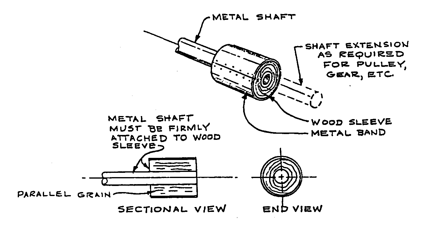
that with metal shafts used in the larger sizes of waterwheels, the bearing will be considerably larger than the required shaft size. A "built-up and banded" bearing may be used. This is accomplished by attaching a wooden cylinder to the wheel shaft at the bearing location to bring the cylinder's outside diameter to the necessary size. Then steel bands are bent and fastened to the cylinder.
Calculating Shaft Size
Waterwheel shafts may be made of wood or steel. The diameter of the shaft depends on the material used and the dimensions of the wheel. The tables below give minimum shaft diameters for bearing loads up to 45.45 kgs.
Minimum Standard Pipe Sizes for Use as Acles With Bearings at 30cm From Wheel Edge Metal Shafts)
Bearing Load (kg) 45.5 91 227 454 908 2270 4540
Pipe Diameter cm) Solid Metal Shaft 2.5 3.75 6.25 7.5 10 15 20
Minimum Standard Hardwood Sizes for Use as Axles With Bearings at 30cm From Wheel Edge (Wooden Shafts)
Bearing Load (kg) 45.5 91 227 454 908 2270 4540
Wood Shaft Diameter (cm) 3.75 6.25 9 18 33 86.5 173
When comparing these figures with the bearing diameters, it can be seen that for pipe or a solid steel shaft, a wooden bearing will need to be built up. With wooden shafts, the required shaft diameter will usually exceed the required bearing diameter giving one the choice of reducing the shaft diameter at the bearing location (but only there) or of using larger bearings.
In either case, the shaft must be banded with steel, sleeved with a piece of pipe, or given some similar protection against wear in the bearing.
APPENDIX V
DECISION MAKING WORKSHEET
If you are using this as a guideline for using the Waterwheel in a development effort, collect as much information as possible and if you need assistance with the project, write VITA. A report on your experiences and the uses of this manual will help VITA both improve the book and aid other similar efforts.
VOLUNTEERS IN TECHNICAL ASSISTANCE 1600 Wilson Boulevard, Suite 500 Arlington, Virginia 22209, USA
CURRENT USE AND AVAILABILITY
* Describe current agricultural and domestic practices which rely on water at some point.
* What water power sources are available? Include rivers, streams, lakes, ponds. Note whether sources are small but fast-flowing, large but slow-flowing, etc.
* What is water used for traditionally?
* Is water currently being used to provide power for any purpose? If so, what and with what positive or negative results?
* Are there dams already built in the area? If so, what have been the effects of the damming? Note particularly any evidence having to do with the amount of sediment carried by the water--too much sediment can create a swamp.
* If water resources are not now harnessed, what seem to be the limiting factors? Does the cost of the effort seem prohibitive? Does the lack of knowledge of water potential limit its use?
NEEDS AND RESOURCES
* Based on current agricultural and domestic practices, what seem to be the areas of greatest need? Is power needed to run currently hand-powered machines such as grinders, saws, pumps?
* What are the characteristics of the problems? Is the local population aware of the problem/need? How do you know?
* Has any local person, particularly someone in a position of authority, expressed the need or expressed any interest in this technology/ If so, can someone be found to help the technology introduction process?
* Are there local officials who could be involved and tapped as resources?
* How can you help the community decide which technology is appropriate for them?
* Given water power sources available which water resources seem to be available and most useful? For example, one stream which runs quickly year around and is located near to the center of agricultural activity may be the only feasible source to tap for power.
* Define water power sites in terms of their inherent potential for power generation. In other words, one water source may be a power resource only if harnessed by an expensive turbine.
* Are any materials for constructing water power technologies available locally? Are local skills sufficient? Some water power applications demand a rather high degree of construction skill. Is surveying equipment available? Do you need to train people?
* Can you meet the following needs?
* Some aspects of the waterwheel project require someone with experience in woodworking and surveying.
* Estimated labor time for full-time workers is:
* 4 hours skilled labor * 40 hours unskilled labor.
* If this is a part-time project, adjust the times accordingly.
* Do a cost estimate of the labor, parts, and materials needed.
* Does the technology require outside funding? Are local funding sources available?
* What is your schedule? Are you aware of holidays and planting or harvesting seasons which may affect timing?
* How will you spread information on, and promote use of, the technology?
IDENTIFY APPROPRIATE TECHNOLOGY
* Is more than one water power technology applicable? Weigh the costs of various technologies relative to each other--fully in terms of labor, skill required, materials, installation and operation costs. Remember to look at all the costs.
* Are there choices to be made between say a waterwheel and a windmill to provide power for grinding grain? Again weigh all the costs: feasibility, economics of tools and labor, operation and maintenance, social and cultural dilemmas.
* Are there local skilled resources to guide technology introduction in the water power area?
* Where the need is sufficiently large-scale and resources are available, consider a manufactured turbine and a group effort to build the dam and otherwise install the turbine.
* Could a technology such as the hydraulic ram be usefully manufactured and distributed locally? Is there a possibility of providing a basis for a small business enterprise?
FINAL DECISION
* How was the final decision reached to go ahead--or not go ahead--with this technology?
APPENDIX VI
RECORD KEEPING WORKSHEET
CONSTRUCTION
Photographs of the construction process, as well as the finished result, are helpful. They add interest and detail that might be overlooked in the narrative.
A report on the construction process should include much very specific information. This kind of detail can often be monitored most easily in charts (such as the one below). <see report 1>

Some other things to record include:
* Specification of materials used in construction.
* Adaptations or changes made in design to fit local conditions.
* Equipment costs.
* Time spent in construction--include volunteer time as well as paid labor; full- or part-time.
* Problems--labor shortage, work stoppage, training difficulties, materials shortage, terrain, transport.
OPERATION
Keep log of operations for at least the first six weeks, then periodically for several days every few months. This log will vary with the technology, but should include full requirements, outputs, duration of operation, training of operators, etc. Include special problems that may come up--a damper that won't close, gear that won't catch, procedures that don't seem to make sense to workers, etc.
MAINTENANCE
Maintenance records enable keeping track of where breakdowns occur most frequently and may suggest areas for improvement or strengthening weakness in the design. Furthermore, these records will give a good idea of how well the project is working out by accurately recording how much of the time it is working and how often it breaks down. Routine maintenance records should be kept for a minimum of six months to one year after the project goes into operation. <see report 2>

SPECIAL COSTS
This category includes damage caused by weather, natural disasters, vandalism, etc. Pattern the records after the routine maintenance records. Describe for each separate incident:
* Cause and extent of damage. * Labor costs of repair (like maintenance account). * Material costs of repair (like maintenance account). * Measures taken to prevent recurrence.