The purpose of this document is to show several water pump designs constructed from PVC pipe, explain how to manufacture them, and discuss pump performance and how to improve on these designs.
Pump Designs
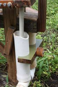
Rower Pump
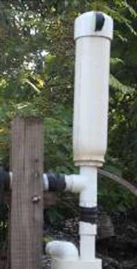
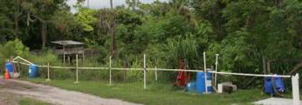
Rower pump installed at a borehole
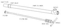
The rower pump is operated using the arm and back muscles similar to rowing a boat. The cylinder is mounted horizontally and the handle is attached directly to the piston rod. It can be positioned either for standing or seated operation. The ergonomic position, combined with the 3 ½ foot stroke, gives the rower pump an output of 10-20 gallons per minute, much higher than other hand pumps. Lift is up to 27 feet suction and at least 8 feet pressure with the use of a rod seal.
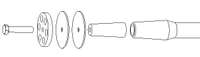
Components
Rower pump components
Dimensions of all components will depend on sizes of available PVC pipe. Listed values are for prototypes built at ECHO. Critical relationships between dimensions are discussed, allowing the designer to build a pump successfully from any size pipe he desires.
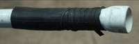
Pump Cylinder
Material: 2” Sch. 40 PVC pipe
Length: 43”
The pump cylinder is the body of the pump in which the piston slides up and down. Deburr both ends of the pipe and glue a Tee onto the top end. Note that American PVC is measured by the inner diameter, while West African PVC which is measured by outer diameter. Sch. 40 is medium wall pipe.
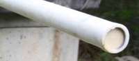
Inlet Pipe
The inlet pipe extends from the foot of the cylinder into the water. The top of the inlet must be equal to the pump cylinder diameter, but it can be reduced to a smaller diameter pipe to save cost and reduce priming time. As a rule of thumb, the inlet pipe diameter should give a flow area ½ that of the pump cylinder. This requires an inlet pipe diameter 0.707 of the cylinder. Don’t use an inlet pipe less than ½ the cylinder diameter; wasted energy due to pipe friction will become significant. However, if you build a surge chamber, smaller inlet pipe can be used (see the testing section).
The inlet pipe will need to be bent depending on the water source and the mounting angle of the pump. See the manufacturing section on bending pipe. If a sharp bend is needed, use a 45 or 90 degree fitting.
Foot Valve
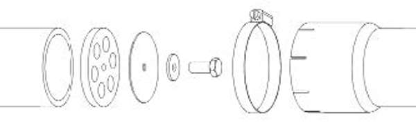
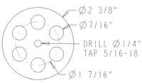
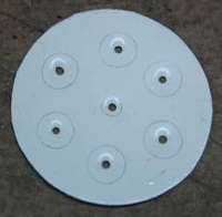
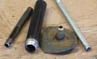
Exploded view of foot valve components
The foot valve is a check valve (one way valve) that allows water into the bottom (foot) of the cylinder but not back out. A rubber washer is bolted to the center of a PVC disc with a radial array of holes. The PVC disc is glued to the top of the inlet pipe and the cylinder is heated and flared over the inlet pipe. The rubber flaps up when the piston sucks water into the cylinder, but bridges over the holes when the water reverses direction. Tighten the bolt until the rubber just starts to lift at the edges. If the rubber is compressed too much in the center, the edges will lift up in a cone shape. This will not prevent the valve from closing during operation, but can make it bounce open and lose prime.
Use a circular punch to make the center hole; this will keep the flap centered and reduce the chance of it pulling off the bolt. The rubber should overlap the valve holes by at least 1/16” to prevent it from being sucked into the hole at the edge, breaking the seal. It should be at least 1/16” from the edge of the PVC valve disc to prevent it from catching on inside of the pump cylinder where it flares out over the foot valve. Bicycle tube rubber is not stiff enough to bridge the valve holes, although layering several pieces may work.
To get the edge exactly flush with the inlet pipe, cut the disc slightly larger, glue it to the inlet pipe, and file it down to the pipe. When tapping the center hole, only run the tap partway through so that the bolt starts easily but tightens up. Make sure the valve holes are at far enough from the edge so that the inlet pipe underneath does not block them. See the section on alternative check valve designs for tips on getting the most flow area for your pipe size without weakening the valve.
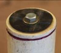
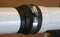
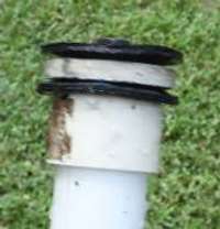
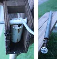
Hose Clamp
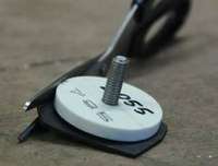
The foot valve joint, wrapped in rubber and hose clamped
The foot valve is held in place with a hose clamp on the foot of the cylinder. Make eight cuts 1/2” deep into the end of the cylinder so the plastic can flex in to grip the inlet pipe. Before putting on the hose clamp, wrap the joint tightly with a strip of bicycle inner tube. This provides additional seal against the small amount of air that will be able to leak between the inlet pipe and cylinder foot.
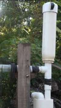
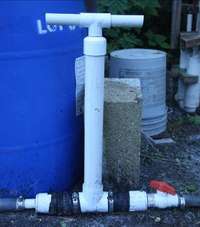
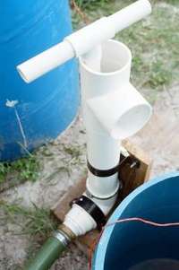
Surge Chamber
Surge chamber on rower pump
Material: 4” PVC pipe and reducers
Length: 18”
The surge chamber (optional) is below the foot valve. It absorbs sharp vacuum spikes created by the piston and evens out the flow of water up the inlet pipe (see the section on pump performance). The surge chamber should have a volume 2x the pump cylinder. The diameter and length are not important if this volume is maintained.
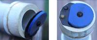
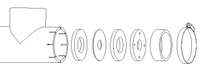
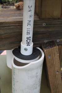
Head Seal
Exploded view of head seal components
The head seal (rod seal) seals around the piston rod so that water can be pumped to higher elevation. A rubber washer is sandwiched between two PVC discs, with a PVC bushing on top to keep the rod centered. These components must be assembled on the piston rod before attaching the handle. They should fit snugly but not tightly into the Tee so they are easy to remove for maintenance.
Rubber washer
Material: truck inner tube at least 1/16” thick
The center is cut using a circular punch. It is very important that the cut is smooth, as small cuts and tears will propagate under the cyclic loading. The diameter should be 1/16” smaller than the rod diameter to give a good seal without excessive friction and stress on the rubber. Double up rubber washers if they are not thick enough.
The disc thickness is required so that as the rubber flexes up and down with the rod, it is not caught in the rod bushing above it. The hole diameter should be at least four rubber thickness larger than the rod diameter to prevent the rubber from binding in the gap as it flexes up and down.
Rod bushing
Material: PVC or HDPE plastic
The purpose of the bushing is to keep the rod centered so it does not deform the rubber and allow leaks. HDPE (#2) plastic wears much better than PVC and has high lubricity. Some plastic barrels are made from it. It can be flattened by heat the same as PVC. Wood is another option: A wood bushing can replace both the bushing disc and the retainer ring. The rod should slide through the bushing with as little clearance as possible without sticking. If you lack precise cutting tools, see “Heat-form a hole” in the manufacturing section.
Retainer Ring
This is a small section of 2” pipe inserted above the head seal components to hold them in place and give the hose clamp something to grip. Size it to leave a small amount protruding from Tee fitting to allow a tool to grip it should it become stuck.
Hose Clamp
Make eight cuts 1/2” deep into the top of the Tee so the plastic can flex in to grip the retainer ring.
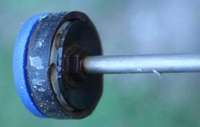
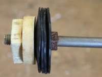
Piston
Exploded view of piston components
The piston slides up and down in the cylinder creating suction to pull water into the pump. In this piston design, the rubber discs serve both as the piston seal and as the check valve flap. On the down stroke the rubber folds out of the way as the piston moves through the water column. On the up stroke, the rubber is sucked down against the PVC disc and water pressure forces it out against the cylinder wall, sealing. This design pumps sand very well because on every stroke the seal breaks contact with the cylinder, allowing any accumulated sand particles to be flushed out.
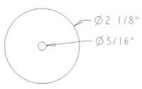
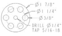
Piston Valve Disc
Piston valve disc dimensions
Material: 4” PVC pipe, flattened (about ¼” thick)
The diameter of the disc should be 1/8” less than the cylinder diameter, giving 1/16” clearance with the cylinder on all sides. It is important that the disc be exactly circular and that the hole be exactly in the center. Water leakage and friction will increase as the precision of the valve disc decreases. When tapping the center hole, only run the tap partway through so that the bolt starts easily but tightens up.
The diameter should be 1/16” greater than the cylinder diameter. This allows the rubber to follow irregularities in the cylinder wall without breaking contact or bunching up at the edges. It is important that the flap be exactly circular and that the hole be exactly in the center. Water leakage and friction will increase as the precision of the valve flap decreases. Use a circular punch to make the center hole; this will keep the flap centered and reduce the chance of it pulling off the bolt. Don’t use bicycle tube rubber; it will stretch at the center hole and the flaps will be pulled off center and bind between the PVC disc and cylinder wall.
The number of rubber discs will depend on the thickness of the rubber and the gap size between the valve disc and cylinder wall. As a rule of thumb, the total rubber thickness should be equal to the gap distance. If the rubber is too thin, water will leak past; if too thick, friction will be excessive and the piston may bind in the cylinder. Tip: add more rubber discs until you feel the rubber grabbing the cylinder wall when you pull slowly on the piston, then use one less.
Piston Bolt
The piston bolt is 5/16-18 x 1 ½” long. Use galvanized, stainless, or painted hardware to resist corrosion.
Wood plug
Material: hardwood
The wood plug is inserted into the end of the PVC piston rod by heating it. The plug is tapered with the large end inserted first to lock it in place. The small end is slightly larger than the pipe diameter. If the end of the rod is greater than ¾” diameter, bevel it so the piston valve holes are not blocked. In the center of the plug, a 1/4” hole is drilled through and tapped 5/16-18 to receive the piston bolt. Tap as deep as the tap will go.
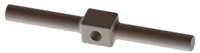
Piston Rod and T Handle
Material: ½” PVC pipe and Tee
Length: Rod is 44”, each side of handle is 5”
Glue both sides of the handle, but attach the rod with two screws through the side of the Tee. The rod must be detached to replace the head seal rubber. PVC pipe is chosen because it is smooth and will wear slowly on the head seal. An added benefit is that the high flexibility of thin pipe allows side to side movement of the handle without putting stress on the head seal. If the pump is abused, the handle will break first, rather than breaking the head seal or cylinder. The piston rod is most easily replaced. See the appendix for additional handle and piston rod options.
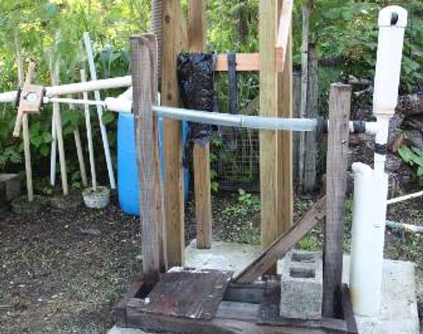
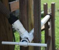
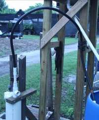
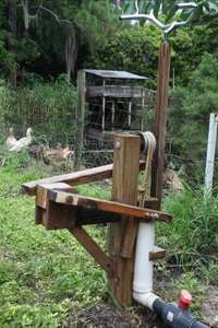
Installation
Cylinder angle
Rower pump clamped between two sets of poles
The best angle for the cylinder will depend on whether you have a rod seal. If yes, set the pump close to horizontal, with the foot valve three inches below the head seal (this will keep water on the foot valve so it does not lose prime). A horizontal pull is most ergonomic both from a standing and seated position. If no rod seal, mount the pump at a steeper angle, 30 deg from horizontal, to reduce the distance water splashes out of the top of the cylinder.
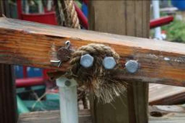
Securing the pump
One option is to burry the pump in a mound of dirt. Another is to plant two sets of poles in the ground at the head and foot of the cylinder. Insert a peg through two poles so the pump can rest between them on it. Lash the poles together to secure the pump.
Sun Protection
PVC degrades in UV light and becomes brittle. Paint the pump, cover it with a shelter, or bury it in a mound of dirt.
Other Rower Documentation
The Mennonite Central Committee (MCC) has a good construction manual for their version of the rower pump. This document is available in electronic form by request from ECHO.
Hand Pressure Pump
Hand pressure pump
The hand pressure pump is operated similar to a bicycle air pump. It is intended to be placed near a water source and force water uphill or over a great distance. The piston is solid, pulling water into the cylinder through one check valve and expelling it through another. Check valves are radial flapper valves inserted in both ends of the Tee at the bottom of the cylinder. The ends of the Tee are slotted similar to the head and foot of the rower pump; by removing the hose clamps the valve discs may be removed. The cylinder is 2” diameter. The 1” plastic hose and ball valve pictured below are for testing only; like the rower pump, it is recommended to use suction and discharge piping at least ½ the area of the cylinder.
Hand pressure pump piston
This pump works most efficiently if some water leaks past the piston seal, providing a water barrier so air cannot leak past the seal on the upstroke. To vent this water so it does not blow off the cap, a ½” hole is drilled in the top of the cylinder directly below the cap (on the dark side of the below photograph). The cylinder cap is only to support the piston rod.
The piston seal is similar to the rower pump, but two rubber seals are used, one on either side of the PVC disc. This creates a seal when the piston moves in either direction. The piston rod is PVC pipe with an end cap, tapped to accept the bolt that holds the rubber and PVC disc in place.
Hand Suction Pump
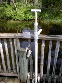
Hand suction pump
The hand suction pump is similar in construction to the rower pump. It is more portable and does not need to be anchored down. Output is probably similar but has not been measured. The pump pictured below has a 3” cylinder and 2” suction hose for large volume at low lift. It is most comfortable to operate this pump if the length of the cylinder requires you to bend slightly at the knees when pumping. This will allow you to pump with your legs.
Marble Pump
Marble pump
The marble pump is named for the glass marbles used for ball check valves in the piston and foot valve. Water is delivered through the piston rod on the down stroke. A flexible hose is attached to the end of the rod for delivery. This pump does not need a rod seal to pump uphill. The small diameter makes it appropriate for wells below the suction limit. It works best as a lift pump (the foot valve and piston should be submerged in the water).
The foot valve is made by compressing the 1.25” pump cylinder over a ¾” pipe, then gluing the smaller pipe in place to make a seat for a 1” glass marble. The marble is held in place by a pin through the cylinder, permitting the marble to rise ½” off the seat.
The plunger is ¾” PVC pipe. A short section of ½” pipe is inserted into the end by heating. A ring of ¾” PVC pipe is inserted over the end of the ½” pipe, creating a groove in which a rubber o-ring sits. The o-ring should be loose, but have no travel up and down in its groove. The marble seats on top of the ½” pipe and is held in place by a pin through the rod that permits it to raise ½ of its diameter off the seat. In lieu of a pin, the rod may be heated and crimped into an oval shape to keep the marble in place.
Marble pump foot valve
Marble pump piston
Sock Pump
Sock pump plunger
The sock pump is named for the “sock valve” on the plunger. A bicycle inner tube is tied to the end of the plunger over a row of holes. The plunger pipe is plugged above the valve holes, and end of the plunger is flared out to slide loosely in the pump cylinder (a wooden mold was turned on a lathe to make this flare). This pump uses the same foot valve as the marble pump (any type of foot valve can be used). On the down stroke, water is forced up through the plunger and out through the holes, but is trapped on the upstroke by the sock valve. The flared plunger forms an imperfect seal, but at high speed the leakage is negligible and is compensated for by lack of the mechanical friction of a rubber or leather seal. Water delivery is through the rising main, not the plunger.
Inertia Pump
Inertia pump plunger
The inertia pump has no piston valve. The piston is a ¾” PVC pipe with a plug in the end. The cylinder/rising main is 1.25” pipe. Any type of foot valve can be used, but it must be submerged at least 4 feet below the water.
The plunger is worked rapidly up and down. On the down stroke and plunger displaces most of the water in the cylinder; the water shoots rapidly up in the small gap between the plunger and cylinder. When the plunger reverses direction, the inertia of the water keeps it moving upward for a moment, creating a pressure drop in the cylinder that pulls more water through the foot valve. The water will lose its momentum and some of it will be pulled back down into the cylinder, but if the speed of the plunger is high, this will be low enough that a significant amount of water may be lifted up the rising main.
The pumping head should not change the amount of water that falls back into the cylinder on the upstroke. Objects thrown upward under the influence of gravity will fall at the same rate independent of their mass. Pumping head will affect the force required to push the plunger down.
The smaller the gap between plunger and cylinder, the more quickly this pump will prime. However, at some point, friction will become significant.
Reciprocating Rope Pump
Reciprocating rope pump
The reciprocating rope pump is a deep well pump in which the piston is attached to a mass and raised and lowered on a rope (it has no piston rod). The mass provides the force necessary for the down stroke. At the top of the pump is a pulley or roller so that the rope can be pulled horizontally in a rowing motion. The piston and foot valve components are otherwise the same as the rower pump. My measurements of the rower pump have shown a force of around 14 lbs is necessary for the piston down stroke. Because 14 lb is a lot to add to the handle force of a pump, the weight on the piston can be reduced, with the result that it returns more slowly. In the photograph below, the piston weighs 10 lb and this gives a tolerable return.
This pump is most appropriate for deep wells where eliminating the piston rod can greatly reduce the cost and make extracting the piston much easier.
Treadle Suction Pump
Treadle suction pump
This is an open top treadle pump most suited for filling irrigation canals. It has no spout to direct the flow of water. It has no base to sit on, but rather a post that is set into the ground. With water pouring around it, the soil quickly settles firmly around the post. If the pump can be set down in a ditch so that the base of the cylinders is submerged in water, it will eliminate any suction air leaks.
The cylinders are PVC pipe. The key to successfully using this weak material in a treadle pump is to isolate it from any structural loads. Water and piston seal friction should be the only forces on the pipe. In the model, the cylinders are clamped to the vertical frame member. The treadles pivot on a 5/8” steel rod which keeps side-to-side wobble low. Cotter pins rather than nuts are used on the pivot rods. They don’t freeze on and are easy to make from steel wire.
The base of the cylinder is a 2” Tee and elbow fitting with rings of 3” pipe compressed over them to expand the diameter. 2” pipe is glued into the fittings and sawed off flush to give a wide surface for the valve seat. Rubber flapper valves are screwed onto the seat (cut the rubber from a tire sidewall). The 3” cylinders are then flared over the foot valves.
Pistons are similar to the rower pump, but sized for 3” pipe.
The rope is anchored to the treadles by hooking it over protruding pins on the outside of the treadle board. This makes it easy to adjust the rope length to allow the maximum travel of the pistons; as the rope stretches, the pistons will sit lower in the cylinders and the stroke length will reduce.
PVC cylinder detail
Piston detail
Rope attachment detail
Manufacturing Processes
Soften PVC by Heating
PVC becomes soft and pliable when heated between 225 and 275 deg F. This behavior can be exploited to make flared pipe connections and flat PVC sheet, increasing the versatility of this material in areas where pipe couplings and flat sheet are difficult or expensive to obtain. Hot air and hot oil may both be used to heat PVC. Oil is more desirable because it gives steady uniform heat, but it takes longer to reach working temperature and is dangerous if spilled or accidentally heated to flash point. Caution: if heated beyond 275 deg F, PVC will scorch and the fumes given off contain dioxins, neurotoxins that bio-accumulate in body tissue.
Hot oil bath
Heat the oil slowly. Test the temperature with a piece of PVC while heating. It should not show any signs of scorching when held in the oil for any length of time. Oil has much better heat transfer properties than air so the desired oil temperature will be only slightly higher than the desired PVC temperature.
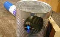
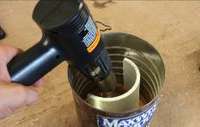
Hot Air
Heating PVC with a torch
Air can be heated by propane torch, electric heat gun, fire, etc. Directing this heat against the pipe is best accomplished by putting a “skirt” around the pipe. It is important to keep either the pipe or the heat source moving constantly, as the air temperature will be very non-uniform. Air temperature will also be much higher than the desired PVC temperature. Air has low heat transfer properties and unless a large temperature difference is maintained, the PVC will heat very slowly. Here are some examples:
A propane torch with skirt made from a tin can. The torch heats the air in the can at the bottom and the pipe is inserted through a hole near the top. The pipe should be rotated constantly for even heating.
Heating PVC with an electric heat gun
An electric heat gun with a tin can. The pipe is inserted into the open top of a tin can and an electric heat gun is aimed down into the can. Keep the heat gun moving to give even heating.
Hold the pipe over a fire. Enough heat is rising over a large area so a skirt is not needed to contain heat around the pipe. It takes practice to heat without scorching.
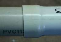
Flare PVC pipe
A flared PVC joint
This process stretches the pipe, increasing its diameter so it will fit over another pipe. Heat the end of one pipe until uniformly soft, then insert it over the other pipe. Allow to cool enough to hold in the hand, then pull the two pipes apart while bending the joint back and forth to loosen it. Only flare a pipe using the pipe that it will be joined to: The heat from the flared pipe can soften the other pipe and contract it slightly. To reduce this effect, cool the pipe every few seconds by pulling it out of the flared pipe and dunking in water briefly. If you need to make a lot of flared ends, it may be worthwhile to turn a wooden mold on a lathe. The mold can be made a few thousandths of an inch larger than the pipe diameter to allow easier insertion of the pipe.
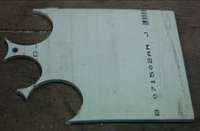
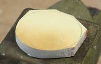
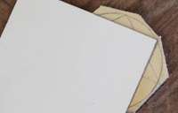
Make PVC sheet
Flat PVC sheet
Cut a short section of pipe lengthwise so it can be unfolded. Heat the pipe until uniformly soft and spread flat and press between two smooth and rigid surfaces. Allow to cool until well solidified. Use a lot of weight when pressing the sheet flat, otherwise it will have ridges and ripples. Soft PVC does not “flow” like pie dough; it remains tough and rubbery. PVC is made of chains of polymers that can slide past each other while above the “glass transition temperature” but always remain partially connected by “cross link” molecules. When pressed between two perfectly flat surfaces, the PVC sheet will still have a slight convex shape when removed due to residual stresses involved in unbending the pipe. To make it perfectly flat, try pressing between two slightly concave surfaces, such as wide wood planks that have warped or cupped. Having been over-bent, the sheet will spring back into a more flat state. PVC has a memory and if you re-heat your flat sheet again, it will curl back into a pipe.
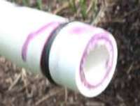
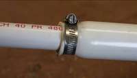
Compress PVC pipe
1.25” pipe compressed onto 3/4” pipe with hose clamp
The principle of flaring PVC pipe can also be applied to reduce the pipe diameter. Put a hose clamp around the end of the pipe, heat the pipe until uniformly soft underneath the hose clamp, insert the smaller pipe and tighten the hose clamp until the larger pipe has compressed against the smaller. Smaller pipes will be lopsided when compressed because the hose clamp screw mechanism puts a flat dent in one side that becomes increasingly noticeable in smaller diameters.
Cut PVC discs
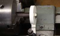
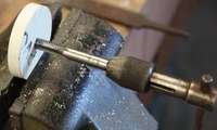
With a lathe
PVC disc turned on lathe
Drill a hole in the center of a piece of PVC sheet and bolt to a steel rod to clamp rod in lathe chuck.
Note: 5/8” diameter steel rod is tapped 5/16 - 18 to receive a bolt which clamps the disc against the end of the rod. This provides a good friction grip on the disc and resists bending forces applied by the cutting tool. Alternatively, a standard bolt or threaded rod with two nuts may be used to hold the PVC.
With a hole saw
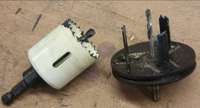
Select hole saw size
If an adjustable hole saw, loosen the nut and rotate the two halves to slide the cutting teeth in and out to give the correct diameter (note that you need an inner diameter because you want to keep the center of the cutout). Tighten the nut.
Fixed hole saw (left) and adjustable hole saw (right)
If a fixed diameter hole saw, find one that is +/- 1/8” of the desired diameter (remember to measure the inside diameter of the saw).
Clamp the PVC sheet to scrap wood to support the saw as it cuts through the backside of the sheet.
Use either a hand drill or drill press to cut the hole
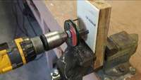
Hand drill: Clamp the scrap wood to a secure object (workbench, vise). Hold the drill with both hands and take care to keep it steady and straight, as this will reduce the change of the saw catching and wrenching the drill out of your hands. Run at a medium speed and feed the saw slowly into the work. Withdraw the saw from the work often and clean the teeth with a wire brush, as the plastic melts to them and clogs the saw
Hole Sawing using a hand drill
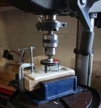
Drill press: Clamp the scrap wood in the drill press vise and adjust the table height to bring the work close to the saw. Turn on the drill press and adjust the speed to 600 rpm. Feed the saw slowly into the work
4. Remove the hole center from the hole saw.
With a saw and file
Mark out the disc diameter on the PVC sheet with a compass or by tracing an object of the correct size.
Hole Sawing using a drill press
Cut outside of this line with multiple saw cuts to give the approximate shape but leave extra material for the file to remove.
File the remaining points down to the line. Make sure to hold the file perpendicular to the disc so the edge is not tapered.
Straight cuts around perimeter of disc, edge filed round
Drill PVC with a hand drill
PVC is soft, and a large bit will wander around a lot before it gets in deep enough to keep itself centered. To make a straight round hole in the correct location, drill a small pilot hole (1/8”) first. This will do a lot to keep the bit centered. For even more accurate holes, step up the diameter by increments of 1/8” until you reach the desired diameter. Note: Drill presses hold both the work and the bit rigidly and there is little benefit from pilot holes.
Twist drill bits will pull themselves rapidly through a soft plastic like PVC, particularly when they have a pilot hole to follow. This rapid cutting of a large chunk out of the plastic can cause it to crack, especially if the hole is near an edge. Try to develop the skill of pushing the drill to get it to bite, then pulling back on it to drill the hole in a slow controlled manner.
Drill rpm depends on the size bit. Small bits must be turned very fast to expel the chips from the flutes on the bit. Large bits should be turned slowly.The speed of the cutting surfaces increases as the diameter increases and the rpm must be decreased in the same proportion to prevent excessive heat buildup that will damage the bit. This is very important when drilling metal, but with softer plastic it is not an issue and bits can be run faster.
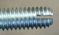
Tap threaded holes
Tapping threads in a PVC disc.
A tap is used to cut internal threads in the hole. Tapping a part often eliminates the need for a nut on the bolt.
Drill a hole smaller than the thread size, approximately equal to the diameter at the base of the threads. Tap drill charts will give the exact size.
Twist the tap down into the hole; push to get it started but after that it will pull itself in.
If tapping metal
Lubricate the tap heavily with cutting oil. Turn the tap 1 turn forward, 1/4 turn backward to break the chip that is formed as metal is shaved off the inside of the hole. This will prevent the tap cutting teeth from getting clogged and binding. Very easy to twist a tap in half if you don’t follow this procedure in metal. Not an issue with softer plastic and wood.
If there is no tap. . .
A steel bolt slit at the end, used to tap softer materials
When threading a bolt into plastic or wood, it is not necessary to tap the hole, the metal bolt will cut its own threads, although it will go in with much more resistance. If you have a very hard wood or plastic, tapping is probably necessary to keep from splitting the wood. If there is too much resistance, the hole can be drilled out larger, but keep in mind that less thread will be in contact with the wood and therefore less holding power.
A crude tap can be made from a steel bolt. Cut a slit in the end of the bolt; the cut edges of thread will be sharp cutting surfaces. Aluminum can be tapped with this method.
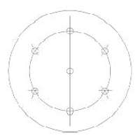
Mark a radial valve hole pattern
With a compass
Marking hole centers with a compass
Scribe a circle that will pass through the centers of the holes. Keeping the compass at the same radius, place the point on the edge of the circle and step around the circle making marks at each step. This will divide the circle into six equal segments and mark the centers of the holes.
Freehand
Draw diameter lines dividing the disc into six roughly equal segments. Measure from the center or edge of the disc and mark the hole centers.
Make a template
Cut a disc from sheet metal and mark out the hole pattern. Punch a small hole to mark the center of each hole. The marks are easily transferred to the PVC disc with a center punch.
Hole pattern template
Index card used to mark endpoints of a circle diameter.
Find the exact center of a circle
Place the point of a square on the edge of the circle and mark where the edges intersect the circle. Draw a line connecting these two marks; it will be an exact diameter. Draw two or three diameters and mark where they intersect.
Deburr a hole or pipe
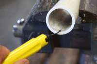
With a deburring tool
Deburring tool removing burrs on inside edge of pipe
Drag the cutting edge clockwise around the inside edge of the hole, applying firm pressure. Deburring tools cut in only one direction, most likely clockwise.
With a file
Filing the inside edge of a pipe
To avoid making grooves in curved surfaces, move the file sideways around the inside of the pipe (draw file). Files cut only in one direction, usually away from you. Don’t cut backwards, it dulls the teeth and plugs them with filings.
Punch a hole in rubber sheet
From left to right: standard circular punch, metal pipe sharpened to a cutting edge, valve stem sharpened to a cutting edge, drilled‐out metal stock sharpened to a cutting edge.
Circular punches make a clean cut in a soft material such as rubber. Place a piece of flat PVC or hard wood underneath the rubber to cut against (don’t use metal, it will dull the cutting edge).
Cut a disc from rubber sheet
Option 1: PVC template
Trace the template (center hole and outer diameter) onto rubber sheet and cut outside of line to leave 1/8” extra material
punch the center hole
bolt the rubber to the template and cut around it with scissors. Make straight cuts, keeping the scissors blade vertical. Do not try to follow the curve of the template, as this will stretch the rubber and the cut will not follow the template.
Rubber disc being cut on template
Option 2: free hand
Trace around an object of correct size. Or, trace an object close to the correct size and measure from this line and make several marks around the circumference to guide you.
Cut out the disc with scissors.
Find the center and punch the hole.
Cut PVC pipe square
Construct a miter box from wood. This is a channel that will cradle the pipe securely while you cut. It has a slot (cut with your saw) perpendicular across it to guide the saw blade. One variation on the standard miter box is to hinge one flange of the channel, making the box adjustable for several sizes of pipe.
Glue PVC pipe
Deburr the edges of the pipe and fitting so they do not scrape off the glue when the pipe is inserted.
Apply PVC primer to both surfaces to clean and soften the pipe surface. Allow primer to dry, leaving a tacky surface. Do not get primer on parts of the pipe that will not be glued together, it has been found to weaken the pipe leading to failure.
Apply PVC cement to both surfaces. Insert the pipe into the fitting while rotating 1/4 turn to evenly distribute the glue. Hold for 30 seconds until set up. The joint will cure over a few hours to reach maximum strength.
Glue a PVC disc to the end of a pipe
Make sure the end of the pipe is square and flat and the disc is flat. To resolve slight problems with either surface, heat the disc and press the pipe down onto it until it solidifies again. Mark their position relative to each other.
When gluing, apply firm pressure to hold the disc against the pipe and hold it for a few minutes at least. Unlike a pipe joint, there is no force to keep the pieces from springing apart while the glue sets. Let cure for several hours before doing anything with this assembly.
Glue a PVC disc inside the end of a pipe
Cut the disc to fit exactly into the pipe with no large gaps
If you are not successful at getting a good fit, heat the pipe and compress it around the disc. Mark their position relative to each other.
Use plenty of glue so that gaps are filled.
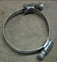
Two hose clamps linked end to end
Make a large hose clamp
Heat-form a hole in PVC
If you need a hole of exact size for a rod bushing, but do not have the necessary tools, try this:
Drill a hole the next size smaller than the desired hole
Heat the edge of the hole to soften it.
Insert the rod to spread the plastic. If the rod is PVC pipe, keep it moving in and out to avoid softening the rod.
This works with PVC and HDPE (#2 plastic). If the hole has to be spread significantly, it will probably be difficult to get the rod started. Try beveling the end of the rod or making a tapered mold from wood.
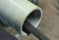
Bend PVC pipe
Fill the pipe with sand and cap both ends. Heat the section to be bent and form it around a bucket or large pipe.
Pump Performance
Definition of terms
Pressure Pump: a pump that moves water by raising its pressure above atmospheric
Suction Pump: a pump that moves water by lowering its pressure. Atmospheric pressure forces water into the pump.
Lift Pump: a pressure pump submerged in a well
Head: vertical distance to which water is being raised.
Pressure Loss (Head Loss): a drop in pressure when water passes through a restriction or length of pipe. This is lost energy.
Rising Main: In a lift pump, the pipe connecting the pump cylinder with the pump head
Suction Pipe: In a suction pump, the pipe from the pump cylinder down to the water.
Pump Head: The above ground mechanism for operating a lift pump
Swept Volume: the volume swept by the piston in the cylinder during the extent of its motion. This may be greater than volume of water output if piston leakage is significant; it may be less than volume output if inertia of water keeps it moving significantly after the piston reverses.
Direct Action Pump: The pump handle is directly attached to the piston rod (no pivoting handle to generated leverage).
Some Principles of Water Pumping
Pumps move water by creating a pressure difference that is great enough to overcome gravity and fluid resistance. In a piston pump this is done by "positive displacement": The water is forced to move by a close-fitting piston in a cylinder. The flow rate is constant with the displacement of the piston and the pressure varies with the resistance of the pipeline. In a centrifugal pump the water is spun with an impeller to raise its pressure by centrifugal force against the impeller housing. The pressure is constant with the rotation speed of the impeller and the flow rate varies with the resistance of the pipeline. The power required to operate a pump is proportional to the pressure difference and flow rate. If not enough power is available, a piston pump will stall and a centrifugal pump will spin but not deliver any water.
A "suction" pump lowers the pressure below atmospheric air pressure so that the atmosphere pushes water into the pump. For this reason, suction pumps are limited in theory to a maximum depth of 34 feet. In practice this maximum suction depth is reduced to around 27 feet due to losses from fluid friction and from accelerating the water on each pumping stroke. A "pressure" pump raises the pressure above atmospheric so that water is pushed out of the pump; the height is only limited to the energy supplied by the operator. Some pumps are capable of both suction and pressure pumping.
Reciprocating piston pumps require two check valves; as the piston moves up and down in the cylinder, water is sucked into the cylinder through one valve and expelled through the other.
Sources of wasted energy in pumps are:
Fluid friction as water increases speed to flow though small orifices in check valves.
Mechanical friction of seals against moving cylinder walls and piston rods.
Force needed to open (crack) check valves.
Pipe friction in the suction or delivery pipe.
Pipe friction is often the most significant because pipe of too-small diameter is used because it is cheaper. Flow friction in check valves and sliding friction in seals can be high in a poorly designed pump.
A suction pump cannot allow air to leak past its piston or it will function very poorly. It is more difficult to make a seal airtight than water tight because air is less viscous (it flows more easily). If the seal has small gaps, negligible amounts of water will leak through, but significant amounts of air. This issue is easily solved by having water on both sides of the piston seal. In many suction pump designs, one of the check valves is part of the piston. On the down stroke, the piston moves through the column of water in the cylinder. On the upstroke, the piston simultaneously expels water from the cylinder top and pulls more water into the bottom through the foot valve.
The need to create suction can be eliminated by placing the pump cylinder below water. Most well pumps are of this type and are referred to as "lift" pumps. Most so-called "pressure" treadle pumps have pistons which only see water on one side. These are capable of suction and are advertised as such, but will work most effectively when the pressure head is much greater than the suction head. Water must leak past the seal so that each piston has water sitting on top of it and does not suck air.
All of the pumps described in this document are intended to be used as direct action pumps, i.e. the handle is directly attached to the pump rod. No leverage is provided. The diameter of the pump is determined based on the water depth. This makes the most sense when you are building the pump yourself and have a wide range of design options. Nothing is gained by using a larger cylinder and then shortening the stroke by use of a lever to gain mechanical advantage. A smaller cylinder with a longer stroke can give the same volume at lower cost.
Rower Pump Performance
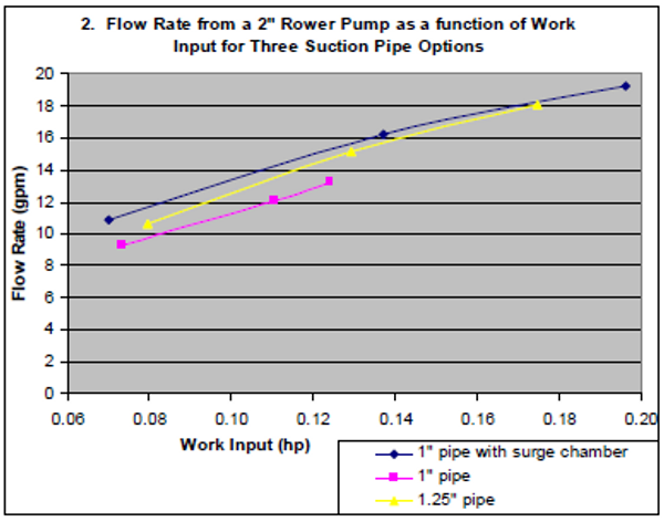
The following tests (graphs 1-4) used a two inch rower pump in a borehole. The suction pipe was 27 feet long and the water level was 7 feet below the pump.
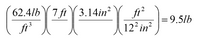
These flow rates seem good until you consider that you are only lifting the water 7 feet. The force required to hold up a column of water can be calculated as F = ρghA.
F = Force (lb)
ρ = (slug/ft3 = lb·s2/ft4)1
g = acceleration of gravity (ft/s2)
A = cylinder cross sectional area (ft2)
For water, ρg = 62.4 lb/ft3
It should only take 9.5 lb of force to lift this water. This is known as the “static head”, the weight of the water column at rest. The rest of the handle force (“dynamic head”) is lost as friction moving the water through the suction pipe and foot valve and as force needed to accelerate the water on each stroke.
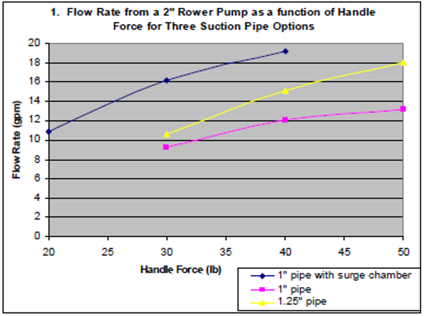
These results look depressing, but consider that a pump this size is not meant for the high flow rates seen in this test. The two inch pump is better matched to deeper wells where it will have more static head and the user will not be able to pump as fast, reducing the dynamic head.
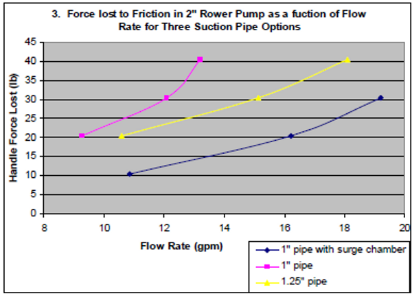
Suppose a well is 27 feet deep, a person is capable of a 50 lb pull, and his pump has a surge chamber: 37 lb of handle force is needed to lift the water (static head), leaving only 13 lb to waste as friction (dynamic head). From chart 3, he can pump about 12 gpm.
For shallower wells, use a larger diameter pump. The rower pump can easily be made from 3” or 4” pipe with corresponding changes in the valve dimensions. A 3” pump can probably be used up to 15 feet deep (static head at this lift requires 46 lb handle force), and a 4” pump used up to 8 feet deep (43 lb handle force). The larger diameter pumps will not need to be stroked as fast to give the same volume, therefore dynamic losses will be much less significant.
For long horizontal runs, pipe friction losses become more significant than valve losses. The following tests (graph 5) used a 2” rower pump in a borehole with varying lengths of horizontal pipe. The suction pipe diameter was 1.25”. The vertical suction pipe was 9 feet long and the water level at 7 feet below the pump.
From this chart we see that the amount of water a person can pump decreases about 3.5 gallons over a 60 foot run. A surge chamber and large diameter pipe are good investments for longer runs.
Can we decrease dynamic losses significantly by using a less restrictive valve? The following chart compares pumps with different foot valves. One is a radial pattern of six 7/16” holes, the other is a side flapper valve over a single 1.5” diameter hole. The flapper valve allows a person to pump four more gallons per minute than does the radial valve. However, it may still be inferior for the application because it is more easily damaged.
Other observations:
I built a rower pump from clear PVC pipe and observed that if the pump is stroked fast enough, the momentum of the water will keep it moving continually upward, even during the down stroke of the piston. The foot valve will never close completely. This eliminates the problem of water leaking back through the valve while it is closing, and the problem of the valve slamming shut and damaging the seat or the flap.
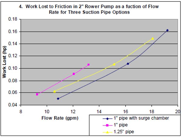
Theorizing about the above results, the surge chamber requires less force at the handle, but volumetric efficiency is lower because a smaller mass of water is accelerated. More strokes are needed to move the same amount of water, so the net power required is similar to the larger pipe. The 1.25" pipe required considerably more force for a given flow rate, but this force takes the water further because its momentum continues to move it up the pipe even after the piston has reversed direction
Marble & Inertia pumps2 Performance
These were very crude tests, measuring how fast the pump could fill a 5 gal bucket. The lift was about 6 feet and the pump cylinder extended 12 feet into the well. The inertia pump could output around 4 gallons per minute and the marble pump could output 5-7 gpm. However, the marble pump was much more tiring to operate and required two hands at the high end of its flow range.
Please note: These performance values reflect a single operator and a single water depth. The inertia and marble pumps react very differently when the pumping speed is changed, as it would if the water were deeper and required more work to lift. The inertia pump greatly decreases in efficiency when it is stroked slower. The marble pump increases in efficiency at slower speed because there is less resistance in the piston check valve.
If the inertia pump will be used at large lifts, it should have a very small gap between the rising main and the plunger so that the water velocity and resistance to reversing direction are high.
Factors that Affect Pump Performance
Fluid resistance and cavitation in check valves
Check valves give a lot of resistance to fluid flow. This translates to more force required at the handle to move the water. Furthermore, as water speeds up to go through the valve orifices, its pressure drops, eventually reaching the vapor pressure. At this point it flashes to vapor (water boils at ambient temperature if the pressure is low enough). When the vapor bubbles collapse, they send shock waves through the water column. The shock wave can burst a pipe, especially at a T or elbow. Or, if the vapor bubbles collapse on a surface inside the pump, they send shock waves through that material and eventually cause pitting and erosion of the surface. This process, called cavitation, is a leading cause of damage to pumps and valves. Cavitation is more an issue in the foot valve of a suction pump than the piston valve because the water pressure is already lower due to the suction required to lift the water. If cavitation is occurring in a hand pump, one solution is to pump slower, reducing the velocity of water through the check valve and thus reducing the pressure drop. Another solution is to make the valve orifices larger, achieving the same result.
Length of piping
The longer the pipe, either suction or discharge, the greater the forces required to accelerate the water on each stroke. The diameter of the pipe does not affect the acceleration force3.
Pipe diameter
The smaller the pipe diameter, the faster water must flow for the same output. Friction in pipes increases with the square of velocity4. Pipe cross sectional area increases with the square of the diameter. So, halving the diameter gives 1/4 the cross sectional area, which gives four times the velocity, which gives 16 times the flow friction. As a rule of thumb, I suggest that the suction pipe diameter be no less than half the diameter of the pump cylinder. Ideally it will be no less than half the area, which requires a diameter 0.707 of the pump cylinder. For a 2” pump cylinder, use 1 1/4” or 1 1/2” suction pipe. If the pipe is running a long horizontal distance, it may be desirable to increase it even more.
Surge chamber
Surge chamber on a rower pump: 4” Sch 40 PVC, 18” long
A surge chamber smoothes out a pulsating flow in a pipeline. In the case of a rower pump, the surge chamber is positioned directly below the foot valve. On the upstroke, the piston sucks half of its water out of the surge chamber, with the other half coming up the inlet pipe. This creates a vacuum in the surge chamber that pulls water back into it during the down stroke of the piston. Thus, the intermittent flow of water in the cylinder is transmitted into a more-or-less constant flow of water in the inlet pipe. Water velocity is half as great and therefore pipe friction is 1/4th as great.
Surge chambers can also be used on the pressure side of a pump. They become more and more necessary the longer the pipeline is and the more water must be accelerated on each stroke. With single piston pumps, they allow use of significantly smaller diameter piping. With treadle pumps, due to their two cylinders delivering water continually, they cannot reduce pipe diameter but still will reduce pressure shocks to the pump if connected to a long pipeline.
As a rule of thumb, a surge chamber should have a volume 2x the cylinder volume. The larger the volume, the smaller the pressure variation in the chamber and the more steady the flow up the inlet pipe. The perfect chamber would maintain a constant pressure regardless of the irregularity of the piston.
Piston seal material
A leather cup seal is pressed against the cylinder wall by the pressure above the piston. This creates a very good seal, but also significant friction if the cylinder wall is not smooth. PVC cylinders are easily scored and roughened by grit that gets trapped between the cup seal and the cylinder wall.
The rubber disc piston seal deflects into the gap around the PVC support disc with increasing pressure. This allows small amounts of water to leak past, increasing as the pressure increases. These losses are insignificant compared to the pump output, but eliminate contact between the rubber and the cylinder, eliminating mechanical friction. Sand in the water is not a problem because the rubber discs fold away from the cylinder on every down stroke, flushing out any sand that may have become trapped. One pump at ECHO was used to bail water from a hole and still functioned even with a foot of sand accumulated on top of the piston.
Designing a Pump: Tradeoffs
Pipe cost
Suction and discharge pipe will often be a much greater cost than the pump. Smaller diameter pipe is cheaper, but you will get less water because more energy will be lost to fluid friction. Invest in larger pipe! Human labor is not cheap! We only put out 1/10 of a horsepower average over a days work and we want to make the most of it.
Piston rod material
Metal is stronger and can be bent back if damaged. Stainless steel and PVC are smooth and will not rust. PVC is weak but easy to replace, and if abused it will break instead of transferring loads to the pump and breaking other parts. PVC flexes more, allowing a person to pull crookedly on the handle without causing a lot of friction in the rod bushing.
Check valves
Side flap check valves have much lower flow resistance, but they are easier to rip off or to become askew so the flap does not fully cover the hole. They also open further and so when they close more water slips back through and the valve slams harder. Sock valves can rip off more easily than flap valves. Larger holes in radial pattern check valves give less resistance but weaken the valve disc.
Overall Cost
It is a general rule that the cheapest pumps will have lower flow rates and use the body less ergonomically. More expensive pumps are built strong enough to use stronger muscles and are more complex in order to use muscles in the most comfortable position. So, the marble pump is very cheap and easy to build, but awkward to operate and gives a small flow rate. The treadle pump on the other hand is most expensive but produces far more water by using the leg muscles.
Alternative Designs for Components
Foot Valve
Variations on the radial hole array:
There are many possible patterns of holes for a valve with a rubber flap bolted in the center of the valve disc. Lay out a pattern of holes appropriate for the diameter of the pump. Considering the following:
The valve must not catch on the cylinder wall when it opens.
The rubber must overlap the holes by at least 1/16” or the edge will be sucked into the hole and break the seal.
Distance between holes should be 1/2 the hole diameter to maintain strength of the disc. If the disc is thicker than 1/10 of its diameter, this may be reduced. Use good judgment.
Maximize the total area of the holes
For the same total area, fewer larger holes give less flow resistance than more, smaller holes.
Holes near the perimeter will give less resistance than holes near the center because water can push the rubber flap further out of the way.
Side flapper valve:
Side flapper foot valve
The side flapper valve is made by flaring and compressing pieces of pipe to build up the end of a 1.5” inlet pipe until the end is thick enough to screw a valve flap to. The 2” pump cylinder is then flared over this assembly. Valve flaps can be made from tire sidewall or from inner tube with a backing disc to give it rigidity.
Piston
Leather cup seal:
Leather cup piston seal
The leather cup is sandwiched between two PVC discs with a radial hole pattern covered by a rubber valve flap. The center of the leather is cut out, leaving a lip about 1/8” wide for the PVC discs to grip. Cut the inner PVC disc to fit the leather cup, but soak the leather first for a few days so you will know its true dimensions. Cut the lower PVC disc to fit loosely inside the pump cylinder. Tap the PVC discs to reduce hardware. When assembling, line up the holes in both discs.
Rubber disc seal with solid PVC:
The rubber disc piston seal can be used without drilling holes in the PVC disc. Make the PVC disc smaller, 1.75” diameter for a 2” cylinder, and there will be sufficient water passage around the disc. Use more rubber discs to bridge the gap. (The square piece is a nut cut from PVC sheet and tapped.)
Rubber disc piston seal
Handle
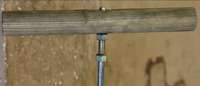
Wood handle for PVC piston rod
PVC piston rod:
Shape a wood handle and bore a hole through the center, slightly smaller than the PVC pipe. Heat the end of the pipe and insert into the hole. When cool, drill through the wood and insert a screw or pin to secure the rod. This will likely be stronger than the PVC Tee handle.
Wood handle for metal piston rod
Metal piston rod:
Drill and tap a hole through the wood handle.
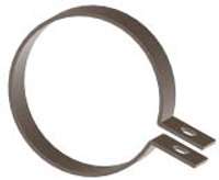
Hose Clamp
Drill a hole in both ends of a metal strap, bend into a hoop with ears sticking out, and put a bolt through the holes. This probably has a tighter grip than a hose clamp and is more easily painted for corrosion protection.
Alternative hose clamp
Testing Methodology and Data
Measured Quantities
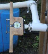
Handle force (lb): mechanical dial force gauge built into pump handle
Volume output (gal): 57 gal plastic barrel
Time (s)
Number of strokes: counted by person pumping
Stroke length (ft)
Calculated Quantities
Flow rate, gallons per minute = volume (gal)/ time (s) * 60 (s/min)
Work input, horsepower (hp) = stroke length (ft) * stroke count * handle force (lb)/ time (s)/ 550 (ft·lb/s per hp)
Dynamic force: subtract static force from total force.
Equipment
2” rower pump with head seal and radial style foot valve
borehole 28 feet deep, water table at 7 feet
platform to mount pump
supports for suction pipe on horizontal run test
55 gal plastic barrel with flapper valve drain in bottom (holds 57 gal to brim)
outlet pipe to barrel
handle force gauge
time piece
Procedure
For each test I timed how long it took to fill the 57 gal barrel. Eyeing the force gauge in the handle, I was able to maintain a constant average force on the handle, within a few pounds.
Rower pump with 27’ suction pipe in borehole
Rower pump with 60’ horizontal run from borehole
Handle force gauge (0‐60 lb)
Raw Data
Table 1. Fixed quantities for all tests
volume
57 gal
stroke length
2 ft
lift, vertical
7 ft
inlet pipe, vertical
27 ft
force piston return
14 lb
Table 2. Test of suction pipe options
1" suction pipe with surge chamber
Force (lb)
time (s)
stroke count
40
178
178
30
211
181
20
315
179
1" suction pipe no surge chamber
Force (lb)
time (s)
stroke count
50
259
138
40
283
159
30
369
169
1.25" suction pipe no surge chamber
force (lb)
time (s)
stroke count
50
189
142
40
226
149
30
323
161
Table 3. Flapper Valve, 1.25” suction pipe. Test using pump with side flapper valve instead of radial valve
force (lb)
time (s)
stroke count
50
154
128
40
182
130
30
242
132
Table 4. Tests of horizontal run
no run
Handle Force (lb)
Time to pump
57 gal (s)
50
196
40
252
30
299
20
480
42
225
55
189
30
297
20' run
Handle Force (lb)
Time to pump
56 gal (s)
40
260
30
374
45
223
50
200
40
257
30
351
45
204
35
296
40' run
Handle Force (lb)
Time to pump
56 gal (s)
50
224
40
309
30
366
45
230
35
301
60' run
Handle Force (lb)
Time to pump
56 gal (s)
50
282
40
337
30
430
45
301
35
393
Appendix
Imperial to metric conversions
Conversion factors
1 inch = 25.4 mm
1 gallon = 3.79 Liters
1 atmosphere = 14.7 psi = 34 feet of water = 10.3 meters of water5
1 ft^3 water = 62.4 lb
1 horsepower = ~550 foot pounds per second = 746 watts
Calculations
Write each conversion factor as a ratio (fraction). Multiply factors together until you get the desired dimensions. Units cancel out when they are divided by themselves: gal/gal=1, just like 4/4=1.
Examples
Convert 10 gallons per minute (gpm) to liters per hour (lph)
Convert 6 meters of water into pounds per square inch (psi)
Acknowledgments
The idea for the rubber disc piston seal and check valve originated with Matt Kiehl at Messiah College in 2003. I later saw a similar design in Wayne Niles’ PVC pump designed in Haiti.
The idea for the rubber disc head seal originated with Messiah College students working on the West Africa Pump Project in 2001.
The rower pump in this document is inspired by the MCC West Africa Rower Pump, although all of the components are different.
Bibliography
MCC Rower Pump construction manual
Wayne Niles pictorial manual for constructing a PVC hand pump (ECHO electronic files)
World Vision Australia brochure for constructing the Rus Pump (EHCO paper files)
Terry Waller, Sketches of a PVC hand pump (ECHO paper files)
Documents describing the Canzee Pump (online)
Messiah College Senior Engineering Project report, 2001: Integrated Pump Design
Contact
jblongen@gmail.com
Revision History: Last modified 25 Oct. 2010 JBL
1 Density is defined as mass per unit volume. A slug is a unit of mass, analogous to the kilogram.
2 The rubber sock ripped off of the sock pump sometime during the test so its results were inconclusive.
3 In a smaller diameter pipe, less water mass is being accelerated, but it being accelerated to a higher velocity. These two effects cancel out.
4 The relationship between flow velocity and fluid friction is complicated for turbulent flow; It is only a rough guess to say that doubling the flow will result in four times the friction.
5 Pressure is defined as a force per unit area, e.g. pounds per square inch: 1 atmosphere is the pressure at sea level exerted by the weight of the earth’s atmosphere. Pressure can also be defined in terms of the weight of a column of water: A 6 meter high column of water exerts a force of 8.6 pounds per square inch. The volume of water has no effect on the pressure, i.e. a 2000 gallon tank and a two inch PVC pipe will have the same pressure at the base if they are the same height.
 The purpose of this document is to show several water pump designs constructed from PVC pipe, explain how to manufacture them, and discuss pump performance and how to improve on these designs.
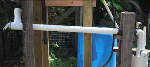

 These results look depressing, but consider that a pump this size is not meant for the high flow rates seen in this test. The two inch pump is better matched to deeper wells where it will have more static head and the user will not be able to pump as fast, reducing the dynamic head.
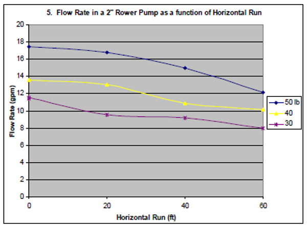 For long horizontal runs, pipe friction losses become more significant than valve losses. The following tests (graph 5) used a 2” rower pump in a borehole with varying lengths of horizontal pipe. The suction pipe diameter was 1.25”. The vertical suction pipe was 9 feet long and the water level at 7 feet below the pump.