Technical Reviewers Dr. Luis Prieto-Portar Alfred Samuel Amde M. Wolde-Tinsae
Published By VITA 1600 Wilson Boulevard, Suite 500 Arlington, Virginia 22209 USA Tel: 703/276-1800 * Fax: 703/243-1865 Internet: pr-info@vita.org
ISBN: 0-86619-306-5 [C] 1990, Volunteers in Technical Assistance
PREFACE
This paper is one of a series published by Volunteers in Technical Assistance to provide an introudction to specific state-of-the-art technologies of intrest to people in developing countries. The papers are intended to be used as guidelines to help people chooe technologies that are suitable to their situations. They are not intended to provide construction or implementation details. People are urged to contact VITA or a similar organization for further information and technical assistance if they find that a particular technology seems to meet their needs.
The papers in the series were written, reviewed, and illustrated almost entirely by VITA Volunteer technical experts on a purely voluntary basis. Some 500 volunteers were involved in the production of the first 100 titles issued, contributing approximately 5,000 hours of their time. VITA staff included Patrice Matthews handling production, and Margaret Crouch as project manager.
The author of the paper, Robert J. Commins, is a retired civil engineer who has helped VITA answer technical questions throughout the Third World.
The paper was reviewed by Dr. Luis Prieto-Portar, the Director of Public Works for the City of Miami, Alfred Samuel, a retired civil engineer specializing in water power, and Amde M. Wolde-Tinsae, a professor with the Department of Civil Engineering at the University of Maryland.
VITA is a private, nonprofit organization that supports people working on technical problems in developing countries. VITA offers information and assistance aimed at helping individuals and groups to select and implement technologies appropriate to their situations. VITA maintains an international Inquiry Service, a specialized documentation center, and a computerized roster of volunteer technical consultants; manages long-term field proejcts; and published a variety of technical manuals and papers.
INTRODUCTION
Bridges are a part of the transportation system of a region. They are used to span an obstacle like a stream or chasm. Bridges make the system more efficient either by saving travel distance or by enabling vehicles or pedestrians to reach places that were previously inaccessible.
There are four basic types of free-standing bridges: beam, arch, truss, and suspension. In addition, pontoon bridges, which actually float on the surface of the water, are used in some situations. While all bridges are built from the basic structural units of bending, tension, and compression members, the design of suspension and pontoon bridges is highly specialized and their construction is usually too costly for small-scale applications. This paper, then, limits its discussion to beam, arch, and truss bridges (Figure 1):
- The beam bridge is composed of members that flex or bend where transverse forces are applied. The first bridge was probably this type of structure: a tree that fell across a stream was used to cross on foot.
- The arch bridge was developed next, first appearing in Mesopotamia about 4000 B.C. The arch bridge is primarily a compression member, subject to forces that tend to diminish its length. This type of structure built of masonry was widely used by the Greeks and later by the Romans. Arches continue to be built, but now reinforced concrete or steel is used.
- The truss bridge is composed of both tension and compression members. A tension member is subject to forces that tend to increase its length. The truss bridge was first built in the 16th century A.D. of wood; many of the covered bridges of the world are still built this way. The development of iron, and later of steel, made truss bridges very popular for intermediate spans (12 to 30 meters). At the same time, the construction of beam bridges became less costly for spans under 12 m. Eventually they, also, were used for very heavy, longer spans.
DESIGN CRITERIA
The site for the bridge should be selected on the basis of minimal cost and maximal convenience for users. Most bridge locations are dictated by such obvious factors as shortest crossing between banks of a river or gulley, the need to join roads of a town, and replacement of an older structure or one that cannot be crossed during floods. Just as there are no low-cost materials of standard quality, there is no such thing as low-cost bridge construction. If funds are insufficient, a smaller structure should be built.
Several questions must be answered before choosing the type of bridge to build:
Why is a bridge needed? The local people must answer this, since they will not only be the primary users but probably the financers, builders, and maintainers of the bridge. Local involvement is vital in planning this kind of project. + What type of traffic will the bridge carry? The type of traffic--pedestrians or vehicles or both--determines the design loads for the structure. Figure 2 shows design loads used in
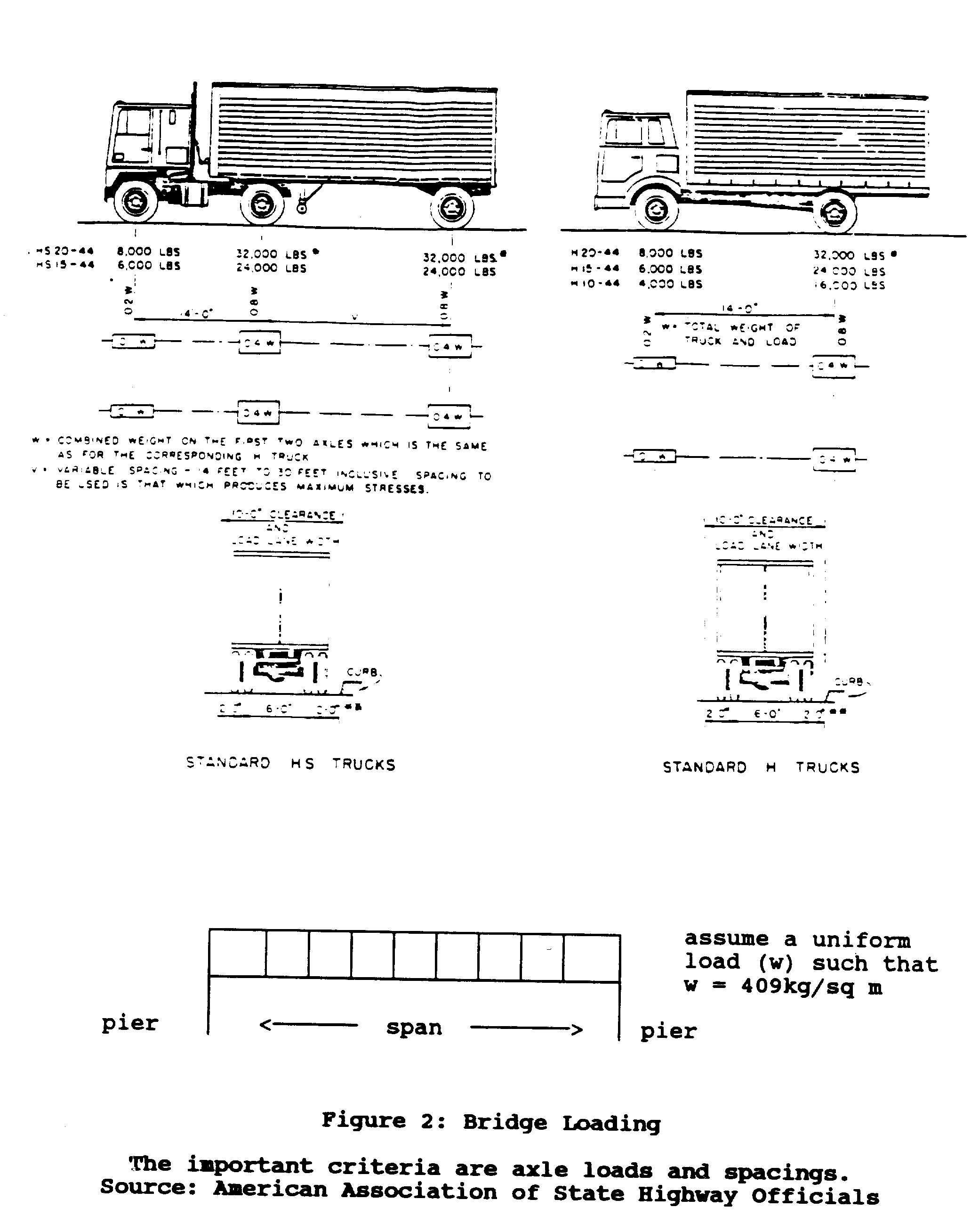
the United States. Local roads authorities should be consulted for loading requirements. If a structure is for vehicles, consideration should be given to future growth of the region and to traffic that may be generated by a more efficient crossing.
- What volume of traffic will the bridge carry? The volume and type of traffic will determine the width of the bridge. For a bridge used for pedestrians, a width of two or three meters is adequate. Vehicular traffic however requires at least one lane of 3 to 4 meters, plus an additional width for pedestrians. If the bridge is to be used by motorized vehicles, a raised sidewalk or curbing should be used to separate vehicular and pedestrian traffic. If the bridge is one way, adequate warning signs for motorized vehicles should be provided.
- What span is required? If the obstacle spanned is a ravine, the answer is simply the width of the gap. In the case of a river the answer is more complex.
A bridge crossing a river should be above the high-water elevation to prevent the bridge from being washed out. It must also provide an adequate underclearance for boats or other river traffic. The needed high-water elevation can usually be determined by examining the river bank and by asking local people the highest water they have observed. Figure 3a illustrates a typical

river crossing. Figure 3b illustrates the case of a wide
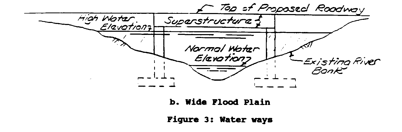
floodplain. In this instance a hydraulic study is necessary, since the size of the floodplain is reduced and the waterway narrowed by the combined widths of the bridge piers. This condition can result in flooding upstream and increased water velocity under the bridge. The increase in velocity can cause severe erosion damage at the bridge site.
a. Ideal situation: maintaining existing waterway area will not affect drive flow in flood stage.
b. The floodstage waterway area is reduced by the crosshatched areas, causing the high water elevation to increase. This increase could cause flooding upstream and erosion at bridge site.
After establishing the need, design loads, width, and length of the bridge, the services of an engineer are required to design the foundations and superstructure. A discussion of types of foundations and superstructure follows, including the information that must be supplied to the engineer.
SUPERSTRUCTURES
The superstructure of a bridge includes the roadway, the footpaths, the railings, and the supporting structural members used to span the required opening. Figures 4 through 8 illustrate

types of superstructure.
Wood Beams
Wood beams (Figure 4) require structural grade timber. Since the
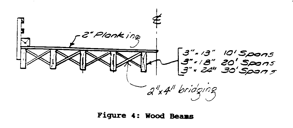
strength of various types of wood varies widely, a source of a structural grade timber of known strength characteristics must be established before considering this type of structure. The wood must be treated with preservatives to prevent rotting.
A wood structure can be built by people with ordinary carpentry skills and tools. The only special equipment that might be needed is some type of lifting device if the bridge beams are of excessive weight.
Concrete Beams
Concrete superstructures can be of the flat slab or of the beam and slab type (both shown in Figure 5). Selection of the type to
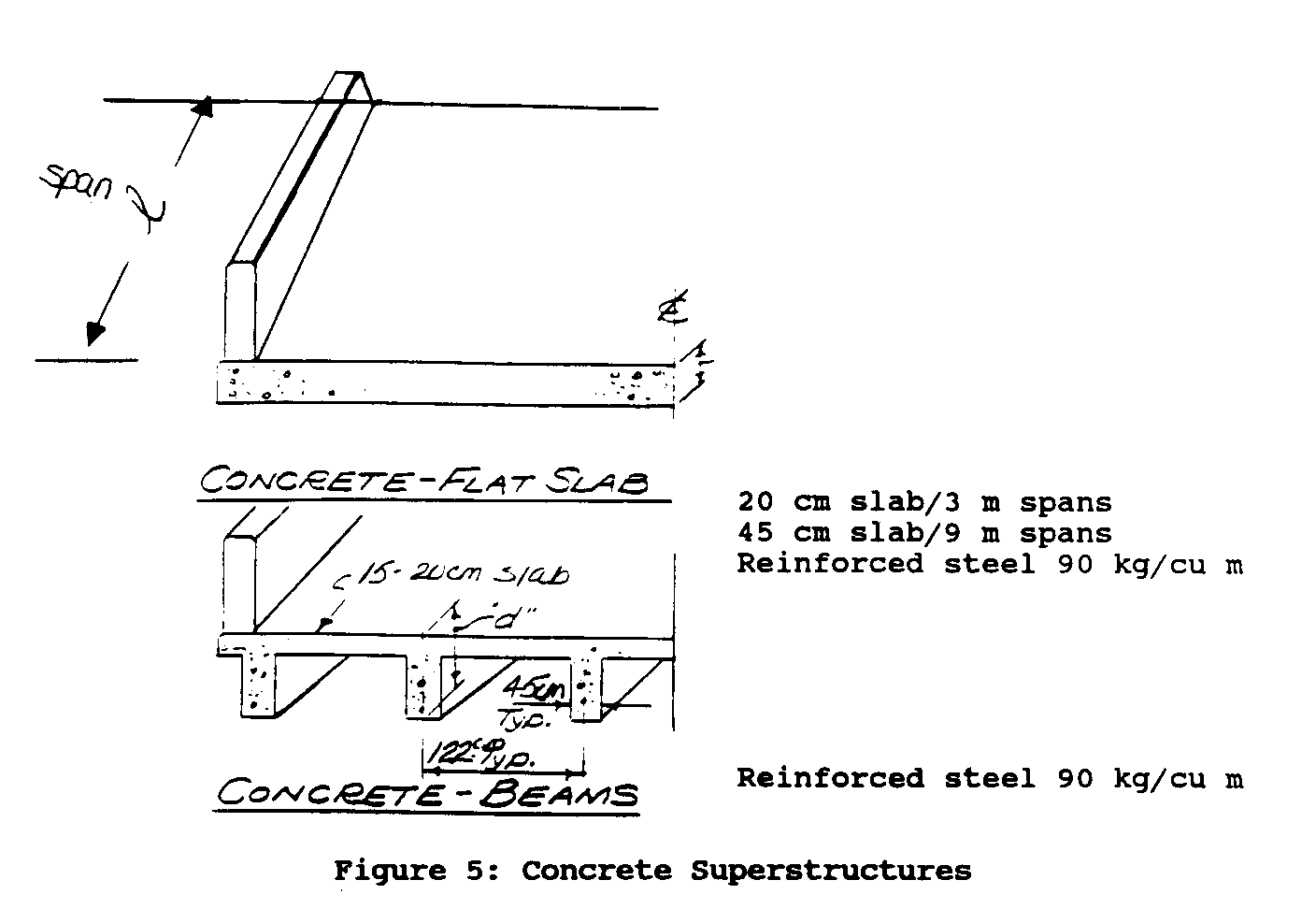
be used depends on the load and span requirements of the structure. The materials required are wood for building forms, cement, sand and gravel, clean (potable) water, and reinforcing steel. Construction of the forms for this type of structure can be complex, because they must be capable of supporting the weight of the concrete until it is cured.
The dimensions shown in Figure 5 are based on the following properties of construction materials:
Wood: Allowable stress = 100 kilograms per square centimeter; allowable shear parallel to grain = 10 to 15 kg/sq cm
Concrete: Allowable compressive stress = 200 kg/sq cm
Reinforcing steel: Allowable stress = 1400 kg/sq cm
Structural steel: Allowable tensile and compressive stress in bending = 1400 kg/sq cm
These properties are listed to help in estimating how much material may be needed. They may be used for preliminary design.
Building the forms requires ordinary carpentry skills. Placing the reinforcing steel and placing and finishing the concrete can be done with unskilled labor, provided that the mixture is properly vibrated to eliminate air spaces. Technical skills are required to design the formwork and determine the appropriate mixtures for the concrete.
Required equipment includes carpentry tools, a concrete mixer, shovels, wheelbarrows, and concrete-finishing tools (trowels, floats, straight-edge, etc.) To avoid the need to build complex forms, sections of the structure can be precast on the ground near the site and then lifted into place after curing. The weight of these members may make it necessary to use a lifting device to set them in place and means must be provided to hold them in place after erection. Precasting and lifting are more complex and dangerous than pouring the concrete into forms that have been built in place. In this case, the hazards arise from removing the forms before the concrete has cured sufficiently to bear its own weight.
Steel
Two types of steel bridges are shown: a truss (Figure 6) and a
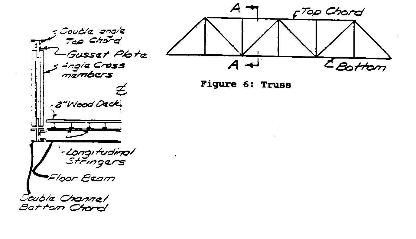
beam (Figure 7) system.
The truss type of structure requires smaller steel members but needs extensive fabrication by a local specialist. Because the needed skills are not common, truss construction may not be an available option.
The steel beam type of structure with a wood or concrete traffic surface can be built locally. Carpentry skills are required for laying the wood deck, or for building forms for the concrete deck. It requires the same skills to build a concrete deck as to build a concrete bridge, but the forming is much simpler.
The needed equipment includes a lifting device to set the steel beams or trusses in place, and ordinary carpentry tools for laying a wood deck. A concrete mixer, wheelbarrows, and shovels are needed to construct a concrete deck, in addition to hand tools and wire that are needed to place and support reinforcing rods.
Arches
A masonry or concrete arch type of structure (shown in Figure 8)
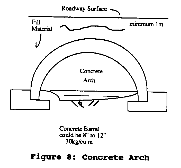
may be considered for short span lengths of 3 to 12 meters. This type of structure, if built of masonry, requires skilled masons and a local quarry for a supply of stone. The forming for an arch is quite complex because curved forms are required to support the weight of the masonry or concrete.
The tools and skills required to build a concrete arch bridge are the same as those needed to build a concrete beam bridge. Carpentry and masonry skills and tools are required if a masonry arch is chosen.
Table 1 gives guidelines for selecting the type of structure to be used for vehicular traffic. The span lengths noted are a general guide for bridges from 3 to 25 meters; they vary depending on design loads.
TABLE I. GUIDELINES FOR SELECTING TYPE OF BRIDGE TO BE USED FOR VEHICULAR TRAFFIC MATERIAL SPAN LENGTH, SKILLS TOOLS COMMENTS
Beam Bridge
Wood 3 to 15 Ordinary Carpentry Wood of known strength carpentry tool characteristics and use of wood preservatives are needed.
Concrete 3 to 10 Ordinary Carpentry Reinforcing steel of (flat slab) carpentry tools, known strength character skills for a concrete istics is needed. Regular forming; mixer, inspection of steel and design wheelbarrow concrete should be made. concrete and shovels mixes of desired strength.
Concrete 3 to 15 As under Con- As under As under Concrete (beam) crete (flat Concrete (flat slab) slab) (flat slab)
Steel 3 to 25 Ordinary Carpentry Steel of known strength carpentry tools. See characterics. skills for also con- forming or crete above placing the if concrete deck. deck is used. Lifting device.
Truss Bridge
Wood 15 to 25 Carpentry Carpentry Structural grade timber tools and is required and skilled a lifting carpenters for fitting device and joining are needed.
Steel 15 to 25 Steel fab- Drills, Truss is made up of rication wrenches, angles or channels, and cutting and skill in fabrication is /or welding needed. equipment for steel, and a Lifting device.
Arch Bridge
Concrete 3 to 10 See Con- See Concrete See Concrete (flat crete (flat (flat slab) slab). In addition, slab) skilled carpenters are required to build curved forms.
Masonry 3 to 10 Carpentry Carpentry Skilled masons and and masonry and masonry carpenters are required to build curves and the forms to support the structure during con- struction.
The maximal wheel loadings and the minimal spacing between vehicles should be established by the community or the authority requiring the bridge. For this purpose, an impact figure should be added to information obtained from vehicle manufacturers.
Sidewalk (footpath) flooring and supports should be designed for a uniform load of 400 kg/sq m, unless a load concentration is expected.
The cost of the structure is not covered in this discussion: it depends on material and labor costs, and these vary widely from region to region.
Maintenance
These types of superstructure require minimal maintenance:
- Wood structures require periodic reapplication of wood preservative.
- Steel structures require periodic painting to avoid excessive corrosion.
- Concrete structures require patching of spalled (flaked or chipped) areas with cement grout if they occur.
Reinforced concrete structures can be difficult to maintain and often impossible to repair. The best defense against the need for maintenance is extreme care in proportioning, mixing, and placing the concrete. Careful placement of reinforcing is equally important.
Broken and spalled concrete areas should be patched; worn roadway surfaces should be given a suitable wearing and paving coat for protection. Cracks should be sealed with a commercial compound recommended for this purpose.
FOUNDATIONS
The foundations of a bridge include those structural units that transmit the loads from the superstructure to the underlying soil. There are two types: piers and abutments. Piers are the intermediate supports for multispan structures. Abutments are the end supports. The types of piers and abutments to be discussed are shown in Figures 9 and 10. Piers and abutments are

supported by foundations, which are of two types: spread footings and piles.
A spread footing (Figure 9) is a shallow foundation and is the
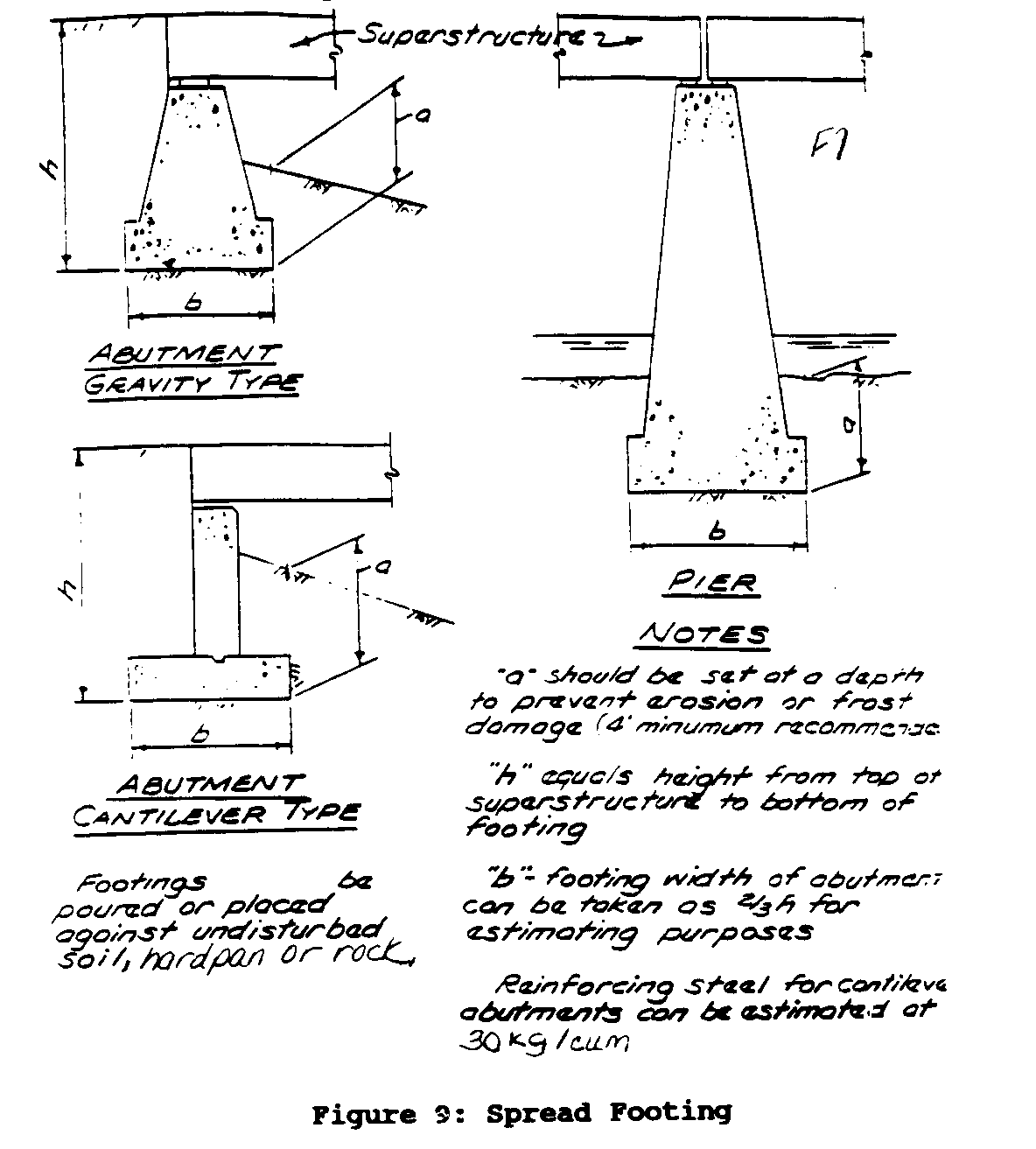
more economical of the two. It can generally be used for small-span bridges (less than 12 meters), provided that the soil can bear the weight (at least 10 T/sq m. Piles (Figure 10) are required
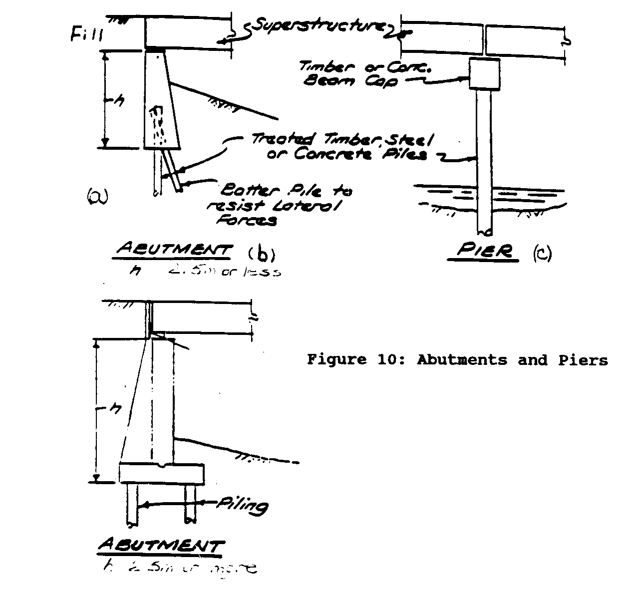
only if soft surface material is found to be incapable of carrying shallow footing loads. Piling is then used to carry the footing loads to a deeper and firmer stratum.
The use of piling requires someone skilled in soil evaluation and boring procedures. This person performs a soil evaluation at the site to determine what kind of piling would be the most economical and what equipment would be required to install the piling.
Abutments
Abutments carry vertical loads from the superstructure and lateral loads from the retained earth on one side (Fig. 10a).
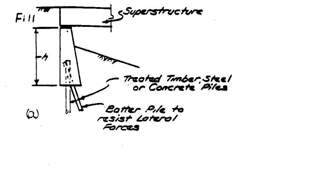
Abutments are of two types: gravity or cantilever. A gravity abutment carries its load through compression, and a cantilever abutment through a combination of bending and compression. Since a gravity abutment is subject to compressive loads only, it can be constructed of masonry or unreinforced concrete. The cantilever abutment requires the use of reinforced concrete to withstand the stress caused by bending.
Piers
Piers carry spans between abutments in order to shorten the deck lengths; they are subject to the following forces: vertical loads from the structure and from the traffic upon it; lateral forces due to the expansion and contraction of the superstructure and to the braking of vehicles on the bridge; lateral forces from water or ice due to stream flow; and lateral forces due to wind loads on the superstructure and to traffic loads. In the case of small-span bridges these forces are negligible except for the vertical loads from the superstructure and the ice pressures in deep rivers of cold-climate areas. If we disregard all forces except the vertical loads from the superstructure, the pier can be considered a compression member and can be built of masonry or unreinforced concrete.
If unreinforced concrete abutments or piers are used, a square mesh of 1.25 cm-diameter reinforcing rods should be placed at 30-cm horizontal and vertical intervals to help control shrinkage and surface cracking. Should a crack develop due to settlement or temperature stresses, the mesh will keep the faces of the crack in contact.
Maintenance
Maintenance of substructure units is normally minimal, consisting of patching of spalled concrete or masonry. Major maintenance occurs only if erosion undermines abutments or piers. In this case filling in the eroded area and placing rock protection to prevent further erosion are required. As prevention, substructure units should be inspected yearly for erosion damage or immediately after unusual run-off.
BIBLIOGRAPHY
- Gidlow, B. Design of Suspension Footbridge, College Camp IN-CE-90
- Strung, N. Your Own T (R)oll Bridge, December. 1990
- Weatherfrod, G.E., Bridge construction using Logs, Timbers, Stones and Soil, VITA Case No. 31977, 1980
- Small Footbridges: Design and Construction, GPO, 1972