Published By VITA 1600 Wilson Boulevard, Suite 500 Arlington, Virginia 22209 USA Tel: 703/276-1800 . Fax: 703/243-1865 Internet: pr-info@vita.org
Understanding Evaporative Cooling ISBN: 0-86619-246-8 [C]1985, Volunteers in Technical Assistance
PREFACE
This paper is one of a series published by Volunteers in Technical Assistance to provide an introduction to specific state-of-the-art technologies of interest to people in developing countries. The papers are intended to be used as guidelines to help people choose technologies that are suitable to their situations. They are not intended to provide construction or implementation details. People are urged to contact VITA or a similar organization for further information and technical assistance if they find that a particular technology seems to meet their needs.
The papers in the series were written, reviewed, and illustrated almost entirely by VITA Volunteer technical experts on a purely voluntary basis. Some 500 volunteers were involved in the production of the first 100 titles issued, contributing approximately 5,000 hours of their time. VITA staff included Maria Giannuzzi as editor, Suzanne Brooks handling typesetting and layout, and Margaret Crouch as project manager.
The author of this paper, VITA Volunteer Eric Rusten, specializes in technology and international development, and has worked in Kenya and Nepal. The reviewers are also VITA volunteers. Michael Bilecky is partner and president of von Otto and Bilecky, an engineering, construction, and energy management firm located in Washington, D.C. Agustin Venero specializes in research and development in new energy sources for the OMICRON Technology Corporation in Berkeley Heights, New Jersey.
VITA is a private, nonprofit organization that supports people working on technical problems in developing countries. VITA offers information and assistance aimed at helping individuals and groups to select and implement technologies appropriate to their situations. VITA maintains an international Inquiry Service, a specialized documentation center, and a computerized roster of volunteer technical consultants; manages long-term field projects; and publishes a variety of technical manuals and papers.
I. INTRODUCTION
Cooling through the evaporation of water is an ancient and effective method of lowering temperature. Both plants and animals use this method to lower their temperatures. Trees, through the process of evapotranspiration, for example, remain cooler than their environment. People accomplish the same thing when they perspire. For both trees and people the underlying scientific principle is the same: when water evaporates, that is, changes from a liquid to a gas, it takes heat energy from the surrounding environment, thus leaving its environment cooler.
We have all experienced the result of evaporative cooling. Sitting under a tree on a hot afternoon is much cooler than sitting either in the direct rays of the sun or in the shade of a building. As water from the tree's leaves evaporates, the air surrounding the tree is gently cooled. Moreover, we have all felt the cooling effect of perspiration evaporating from our skin. Finally, some of us may have discovered that water kept in a canvas bag, porous clay container, or in a canteen with a water-soaked cloth cover, is much cooler, especially on a hot day, than water kept in plain metal or plastic containers. As the water evaporates from the surfaces of these containers it draws heat away from the containers and the water they hold, as well as from the air around them, thus leaving the water cooler.
Since it is possible to cool trees, water bottles, and ourselves by this process shouldn't it be possible to cool other things, such as food and dwellings? The answer to this question is a definite yes. Several systems have been designed to use the principle of evaporative cooling to keep homes cool and comfortable. Also, methods have been developed that reduce the temperature of foods, such as fruits, vegetables, and dairy products, far enough to retard spoilage.
Although lowering the temperature of fruits and vegetables to levels that retard spoilage is an important benefit of evaporative cooling, it is not the only one. Evaporation not only lowers the air temperature surrounding the produce, it also increases the moisture content of the air. This helps prevent the drying out of produce, and therefore extends its shelflife.
In general, evaporative cooling can be used where:
1. temperatures are high;
2. humidity is low;
3. water can be spared for this use; and
4. air movement is available (from wind or electric fans).
This paper provides an introduction to the process of evaporative cooling. In addition, the natural limitations and problems associated with this process, along with some practical applications of evaporative cooling are examined.
II. BASIC PRINCIPLES OF EVAPORATION AND EVAPORATIVE COOLING
As noted earlier, evaporation is the process of changing a liquid into a gas. In this case liquid water becomes water vapor, and this gas becomes part of the mixture of gases that compose the air. The change from the liquid state to a vapor requires the addition of energy, or heat. The energy that is added to water to change it to a vapor comes from the environment, thus leaving the environment cooler.
Not all substances need to gain or lose the same amount of energy to change from one physical state to another. For example, it takes much more heat energy to cause a given amount of water to vaporize than to cause the same amount of alcohol to do so. Water is unique in that it requires a relatively large quantity of heat energy to change from a liquid to a gas. It is this characteristic that enables evaporating water to lower substantially the temperature of its environment.
On the other hand, the amount of water vapor that can be taken up and held by the air is not constant; it depends on two factors. The first is the temperature (energy level) of the air, which determines the potential of the air to take up and hold water vapor. The second factor is the availability of water. If little or no water is present, the air will be unable to take up very much.
The measurement of the amount of water vapor present in the air is spoken of as the air's humidity. There are two ways of measuring the humidity of the air: (1) absolute humidity and (2) relative humidity. Absolute humidity is the measurement of the actual quantity of water (measured in grams) in a given volume of air (measured in cubic meters or liters). Relative humidity, the more common measurement, is the measurement of the water vapor in the air as a percentage of the maximum quantity of water vapor that the air would be capable of holding at a specific temperature. Air that is fully saturated--that is, contains as much water vapor as possible--has a relative humidity of 100 percent, while air that has only half as much water vapor as it possibly could hold at a specific temperature has a relative humidity of 50 percent.
The relative humidity varies with the temperature. As the air cools (i.e., loses energy), its ability to hold water vapor decreases, which results in an increase in the relative humidity. This is because the ability of the air to hold water vapor has been reduced by the drop in temperature, but the absolute humidity (the actual amount of water vapor in the air) has remainde unchanged. If the air temperature continues to fall the relative humidity will approach 100 percent, or complete saturation. The point at which the air is fully saturated is referred to as the dew point. At temperatures lower than the dew point, water vapor condenses out of the air onto cooler surfaces.
DETERMINING RELATIVE HUMIDITY
Before attempting to implement any of the evaporative cooling systems discussed in Section III of this paper, it is necessary to determine if environmental conditions, particularly the relative humidity, are suitable for the evaporative cooling process. In some situations it may be possible to use already existing data, but where this information is not available it will be necessary to collect it.
The following materials are needed to determine relative humidity: a thermometer, a small piece of cloth, a small glass or plastic vial for water, and two pieces of cardboard or some other stiff material (the pieces of cardboard should be longer than the thermometer and as wide as half its length).
The procedure to determine relative humidity involves two steps. First, use the thermometer to determine the temperature of the air; note this down as the dry-bulb temperature (i.e., the temperature taken with the bulb of the thermometer kept dry). Second, secure a small piece of cloth to the bulb of the thermometer with some thread. The end of the cloth should extend beyond the tip of the bulb. Then attach the thermometer to the piece of cardboard. Next, attach the small plastic or glass vial to the cardboard just below the end of the thermometer so that the piece of cloth will fit in the vial. The cloth covered bulb of the thermometer should be left exposed to the air. Figure 1
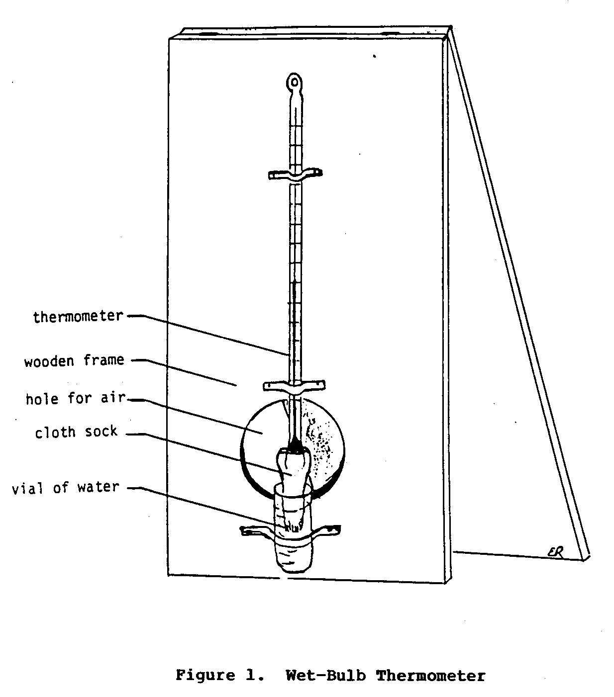
shows the final set-up of this apparatus.
Now, fill the vial with water so that the cloth and the bulb will be kept wet. Using the other piece of cardboard, fan the lower end of the apparatus for 30 to 60 seconds. At the end of this time note down this temperature as the wet-bulb temperature (i.e., the wet-bulb thermometer temperature taken with the bulb end of the thermometer kept wet). Repeat the final steps several more times to ensure accuracy. Add all of the wet-bulb temperatures together and calculate the average wet-bulb temperature.
Use the dry- and wet-bulb temperatures, and the charts in Appendix A
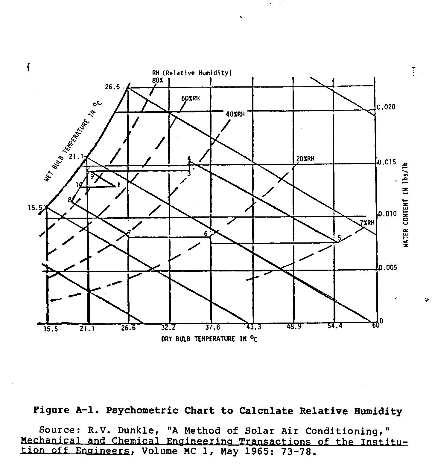
determine the relative humidity for more than one time of the day, and for more than one day. Several calculations over the middle portions of a day, several times a month should be enough to determine if evaporative cooling would be effective in a specific environment. Exactly how relative humidity data are used to determine the effectiveness of evaporative cooling will be discussed later.
FACTORS AFFECTING EVAPORATION
As discussed earlier, evaporation results in cooling of the air or other substances. As the rate of evaporation increases so does the rate of cooling. To make the most effective use of this technology it is important to understand the factors that influence the rate of evaporation, and the relationships that exist between these factors.
There are four major factors that affect the rate of evaporation. Although each of these factors will be discussed independently, it is important to keep in mind that they usually interact with each other to influence the overall rate of evaporation, and therefore the rate and extent of cooling.
Factor 1: Relative Humidity
Relative humidity, as mentioned earlier, is the measurement of the amount of water vapor in the air as a percentage of the maximum quantity that the air is capable of holding at a specific temperature. When the relative humidity is low, only a small portion of the total possible quantity of water vapor that the air is capable of holding, is being held. Under this situation the air is capable of taking on additional moisture, and if other conditions are also met, the rate of evaporation will be higher. On the other hand, when the relative humidity is high, the rate at which water evaporates will be low, and therefore less cooling will occur. Under such conditions of high relative humidity, evaporative cooling may not be effective. However, in many areas with high relative humidity, such as the humid tropics, evaporative cooling can be effective if a dessicant (e.g., silica gel) is used to remove moisture from the air before it is cooled.
Factor 2: Air Temperatures
Evaporation, as stated earlier, occurs when water absorbs sufficient energy to change from a liquid to a gas. Air with a relatively high temperature will be able to stimulate the evaporative process and also be capable of holding a relatively great quantity of water vapor. Therefore, areas with high temperatures will have higher rates of evaporation, and more cooling will occur. With lower air temperatures, less water vapor can be held, and less evaporation, and cooling will take place.
Factor 3: Air Movement
Air movement, either natural (i.e., wind) or manmade (i.e., with a fan), is an important factor that influences the rate of evaporation. As water evaporates from a surface it tends to raise the humidity of the air that is closest to the water's surface. If this humid air remains in place, the rate of evaporation will start to slow down as humidity rises. On the other hand, if the humid air near the water's surface is constantly being moved away and replaced with drier air, the rate of evaporation will either remain constant or increase.
Factor 4: Surface Area
The area of the evaporating surface is another important factor that affects the rate of evaporation. The greater the surface area from which water can evaporate, the greater the rate of evaporation. A simple example will demonstrate the importance of surface area to evaporation. Consider the following two situations. (1) one liter of water placed in a narrow glass container with only about 16 [cm.sup.2] of surface area exposed to the air; and (2) another liter of water poured into a large shallow pan with about 180 [Cm.sup.2] of surface exposed to the air. Of these two situations, which one could be expected to dry up first, if both where left under the same environmental conditions? Because of the large surface area, the large pan of water would dry up much sooner than the jar.
Even though each of these factors has its own separate and significant effect on the rate of evaporation, when combined, their impact is much greater. For example, the first two factors can be discussed together in terms of wet- and dry-bulb temperatures. Under conditions where the difference between the wet- and dry-bulb temperatures is great, the rate of evaporation will also be great. The graph in Figure 2 should help explain this situation.
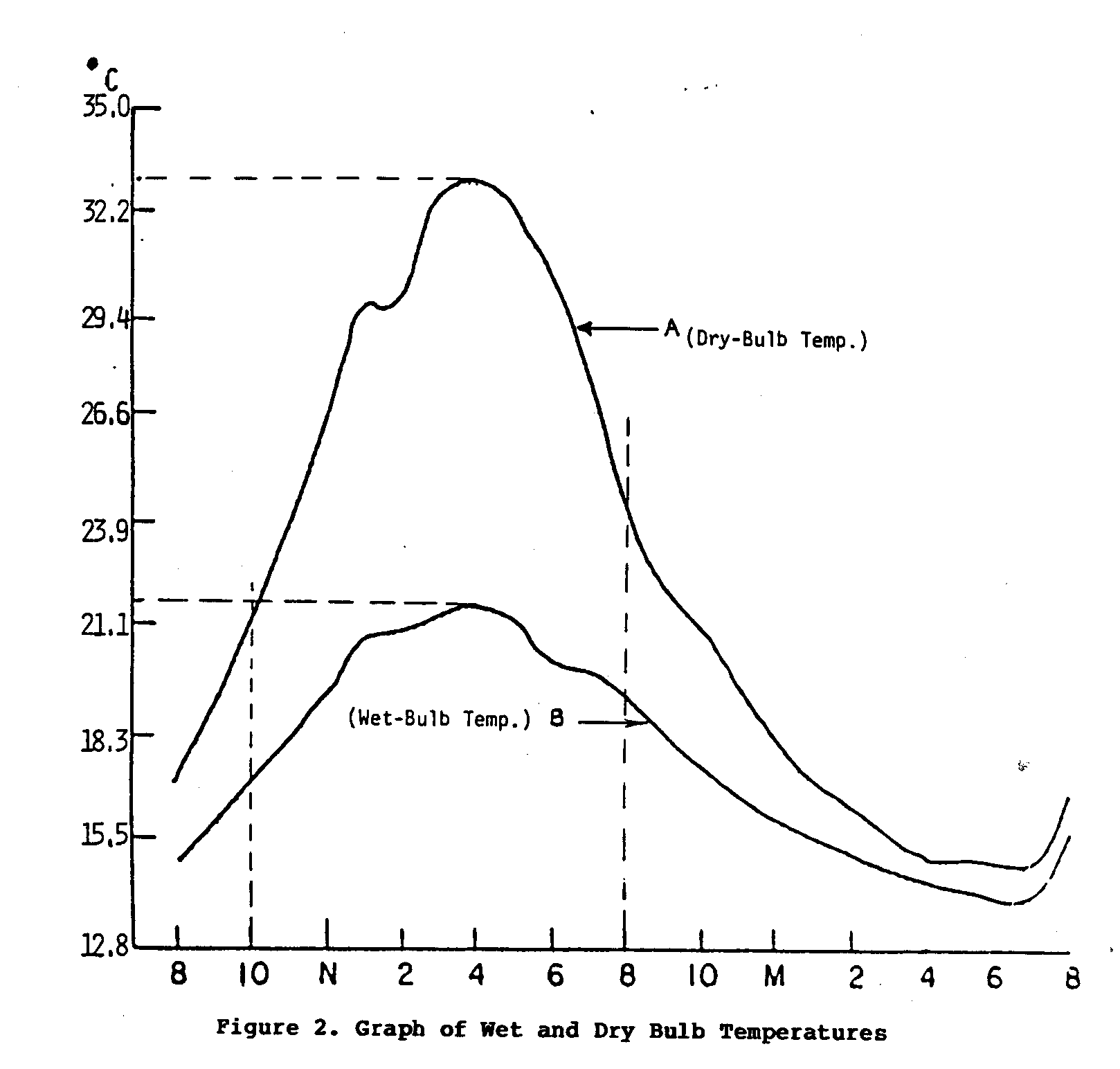
Curve A traces the change in the air temperature (dry-bulb temperature) over a 24-hour period; Curve B traces the wet-bulb temperature, also recorded over a 24-hour period. The difference between the wet- and dry-bulb temperatures is the greatest during the period from 10:00 a.m. to 8:00 p.m. From this it can be reasoned that the relative humidity over this period was low. This is also the time period with the highest average air temperatures. Thus, under these conditions it can be assumed that the rate of evaporation would be relatively great. If the two other factors, air movement and surface area, are applied effectively, the rate of evaporation would show an additional increase.
MAXIMUM COOLING POTENTIAL
The extent to which evaporation can lower the temperature of a container or the air depends upon the difference between the wet- and dry-bulb temperatures. Theoretically, it is possible to bring about a change in temperature equal to the difference in these two temperatures. For example, if the dry- and wet-bulb temperature were 35[degrees]C and 15[degrees]C respectively, the maximum drop in temperature due to evaporative cooling would theoretically be 20[degrees]C. In reality, though, while it is not possible to achieve 100 percent of the theoretical maximum temperature drop, however, a substantial reduction in temperature is possible.
Depending on the environmental conditions, and the method of evaporative cooling used, it should be possible to achieve between 50 and 80 percent of the theoretical maximum drop in temperature. In the example given above, this would have resulted in a temperature reduction of between 10 and 16[degrees]C. III. DESIGN VARIATIONS
There are two general methods of evaporative cooling: direct and indirect. Direct evaporative cooling involves the movement of air past or through a moist material where evaporation, and therefore cooling, occurs. This cool moist air is then allowed to move directly to where it is needed. In contrast to this process, indirect evaporative cooling uses some form of heat exchanger that uses the cool moist air, produced through evaporative cooling, to lower the temperature of drier air. This cool dry air is then used to cool the environment, and the cool moist air is expelled.
In situations where cool dry air is more desirable than cool moist air, the extra effort or expense involved in building or buying and using a heat exchanger may be justified. On the other hand, many situations exist where it will be better to use the less complex and less costly direct evaporative cooling process.
Evaporative cooling technology is used to cool rooms, homes, food, or water. The method of evaporative cooling used, direct or indirect, depends on: (1) the specific needs of the environment that will be cooled; (2) the availability and cost of commercial energy; and (3) the amount of money and skill available to buy or build the cooler.
The following discussion will present specific examples of how both methods of evaporative cooling can be applied. The advantages, disadvantages, and limitations of each of these applications are also examined.
DIRECT EVAPORATIVE COOLING
One of the simplest and most commonly used forms of evaporative cooling is used to cool water. This system usually uses either a porous clay container or a watertight canvas bag in which water is stored. These containers are then either hung or placed so that the wind will blow past them. The water in the containers slowly leaks through the clay or canvas material and evaporates from the surface as warm dry air flows past. This process of evaporation slowly cools the water.
Small bottles, bags, or jars of produce, medicine, or dairy products can be suspended in the water so they can be kept cool. This method of evaporative cooling is common among street vendors of South Asia, who use it to cool soda pop and fruit for their customers.
This type of evaporative cooler has limited application. One of the primary limitations is that the drop in temperature will generally be only a small fraction of the total temperature reduction that is possible. This is primarily due to the large volume of water that needs to be cooled by a relatively small evaporating surface area. Secondly, only a small number of items can be placed in large water containers. The following section of this paper outlines some common examples of other evaporative coolers. Before any of these types of coolers are built or installed, it is necessary to consider the probable effectiveness of evaporative cooling in the specific environment and to balance the benefits gained against costs incurred.
The following section of this paper outlines some common examples of other evaporative coolers.
Outdoor Curtain Cooler
A variation of the simple process described above can be used to cool small outdoor areas (Figure 3). In its simplest form this
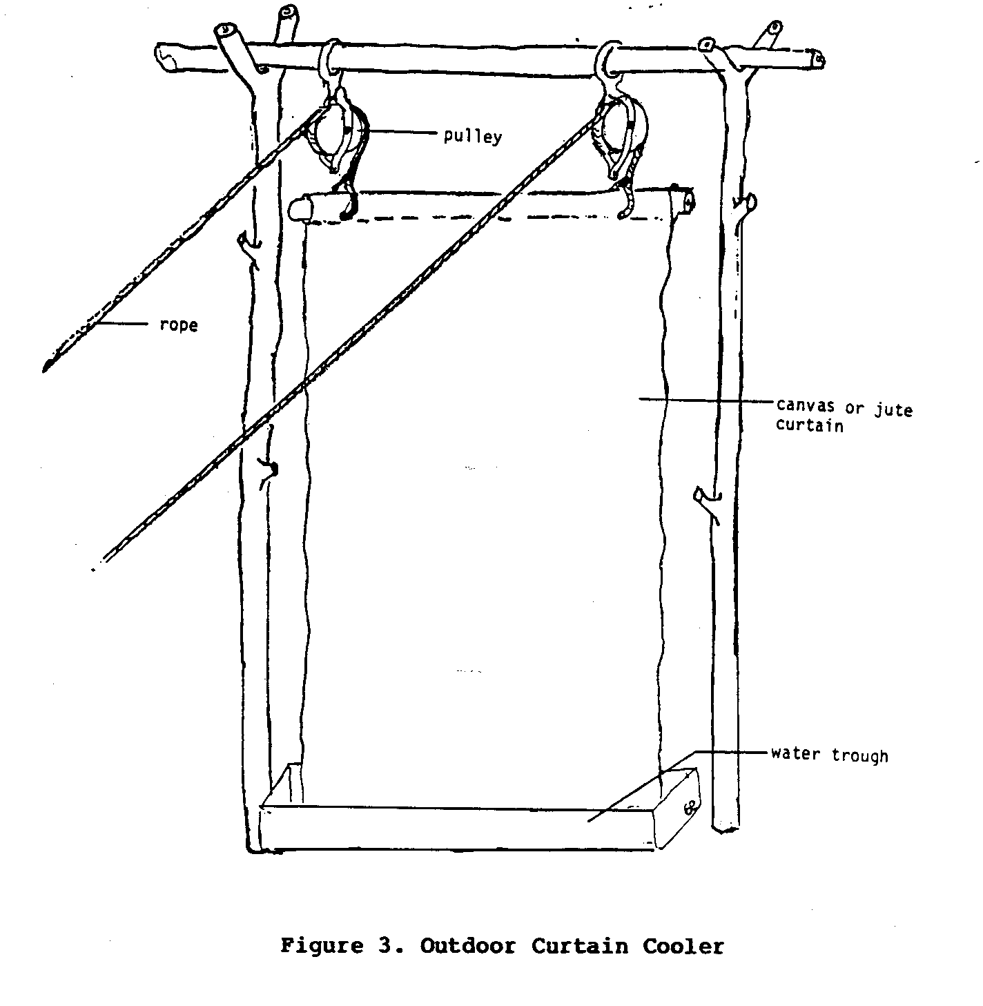
involves the use of a sheet of canvas or some other strong, absorbent cloth as an evaporating surface. The upper edge of the canvas sheet is suspended by ropes that are usually held up by pulleys so that the sheet can be lowered and raised easily. The lower end of the sheet is secured in a trough of water large enough to permit all of the sheet to fit. When a cooler environment is desired the canvas sheet is lowered into the trough of water so that it becomes soaked with water, after which, it is raised. As hot, and generally dry, air passes through and around the moist cloth, evaporation occurs, which in turn cools the air. This cool moist air then cools the immediate environment.
Obviously, the size of the area that can be cooled using this method is limited. Moreover, this cooler can not substantially lower the air temperature. Even with these shortcomings, people who have used these simple coolers have said that they do a fairly effective job of making the immediate environment more comfortable. The simple nature of this cooler is its primary advantage. If a more comfortable outside environment is desired, but cost is an important consideration, this cooler may be a good choice.
Indoor Curtain Cooler
Therather simple device described above can be adapted for use indoors. Again, canvas, jute cloth, a coconut husk mat, or some other absorbent material is used to expose water to moving air.
For use indoors, such a cooling device requires some form of energy source, generally electricity, to power a fan to blow the air through the absorbent material. A small water pump is also needed to circulate water from a lower trough to an upper one. This keeps water continually flowing through the absorbent material so evaporation can occur. Coolers of this type are used extensively in the hot, dry areas of the western United States.
Figure 4 illustrates one such system used in a small restaurant,
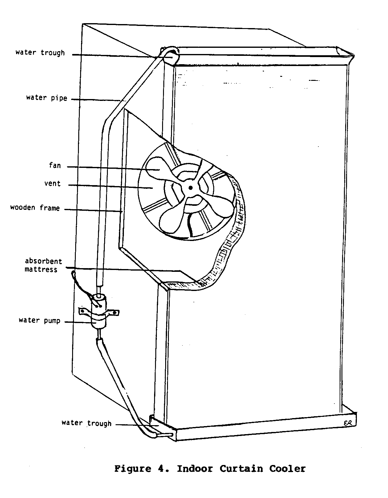
in New Delhi, India. During the hottest part of the day the owner of the restaurant would first start the water pump, and wait for the coconut mat to become soaked with water. After this, the fan would be turned on to force hot dry air through the water-soaked mat. The thickness and density of the mat were sufficient to slow the speed of the air and permit enough evaporation to cool the air substantially. This air was, in fact, cool enough to keep people from sitting close to the cooler for even short periods of time.
Even though this cooler is very effective at cooling room air, it has several important disadvantages. First, this system depends on electricity to power both the water pump and the fan. Second, the cool air that is blown into the room has a relative humidity of nearly 100 percent. In some situations this high level of humidity may be an undesirable since it may promote the growth of mold and mildew. The small restaurant in India that used this system avoided this problem by having only part of the restaurant covered by a roof. This allowed the saturated air to quickly escape outdoors. A further disadvantage of this method is its constant consumption of water. In areas where water is in short supply, its use for cooling purposes may not be justified. Despite these disadvantages, this cooler is capable of cooling an indoor area at a fraction of the cost of a commercial refrigerated air conditioning system.
Cabinet Produce Coolers
Large amounts of fresh produce and dairy products are lost due to spoilage in many tropical and subtropical areas of the world. If this food could be stored at relatively low temperatures until eaten or sold, much of this waste could be avoided. For many of these areas, though, commercial methods of cooling food are either unavailable or too expensive. Evaporative cooling may be a practical alternative for use in tropical and subtropical regions.
There are several types of cabinet coolers that use the principles of evaporative cooling to cool stored produce. Four types of cabinet coolers are described below, in order of increasing complexity.
Type I Cooler
This simple cooler (Figures 5 and 6), which is essentially a
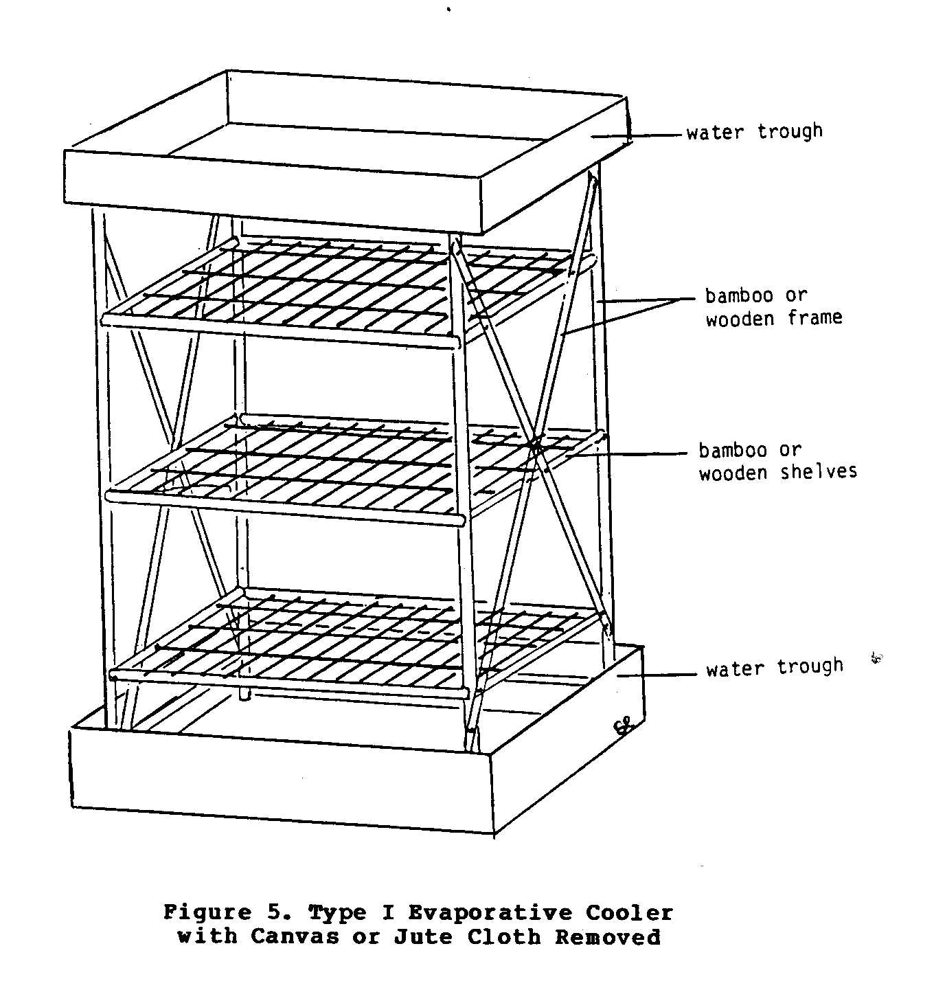
variety of materials ranging from bamboo to sawed timber. It can be cylinderal or rectangular in shape. The cloth covering (Figure 6) that surrounds the cabinet cooler absorbs water from
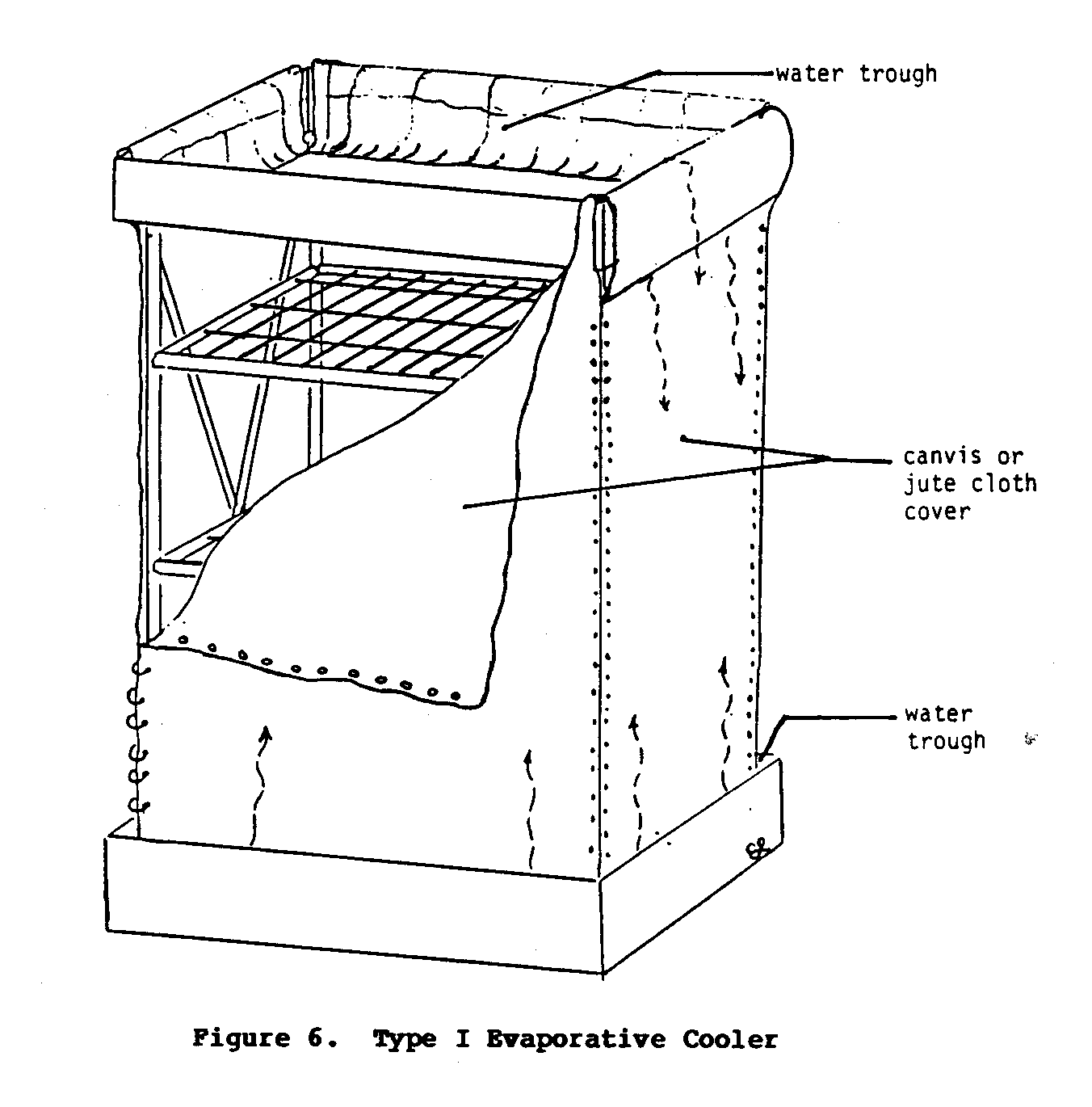
the troughs at the top of the base. Eventually the entire cloth becomes soaked with water, and as the air moves past the wet cloth, evaporation occurs. As long as evaporation takes place, the contents of the cabinet will be kept at a temperature lower than that of the environment.
Under certain conditions, this simple cooler may be unable to maintain low temperatures. For example, if the air is very dry and the wind very brisk, the drying action may exceed the absorbing action of the cloth, thus preventing it from staying moist. This in turn will prevent the cooler from achieving and maintaining a temperature much lower than the environment's. This type of cooler requires periodic attention to refill the water troughs, which may be a problem. The consumption of water may also pose a problem for areas where water is either scarce or difficult to obtain.
The major advantages of this cooler are its relative simplicity, low construction costs, and independence from commercial energy.
Type II Cooler
The Type II cooler was designed to eliminate some of the problems associated with the Type I cooler. The design of the Type II cooler is much the same as the Type I cooler, except that the walls of the Type II cooler are thicker and the water trough is replaced by containers of water that are positioned on top of the cooler.
The walls can be constructed from a variety of materials as long they meet the following requirements: (1) the material must allow air circulation; (2) it must very absorbent and capable of holding a substantial amount of moisture; and (3) the material itself, or the frame surrounding it, must be strong enough to support the containers of water that will sit on top of the cooler. One of the walls of the cooler also functions as a door. Inside the cooler, lattice shelves are spaced wide enough apart so that there is as little obstruction to the air flow as possible.
Small holes are punched along the outer edge of the bottom of the water containers. This allows the water to drip slowly down to the absorbent wall material. The drip flow should be fast enough to keep the walls continually moist, but not so fast as to allow water to drip out of the bottom of the cooler. Obtaining the exact rate of flow requires some experimentation, but with patience, an optimal flow rate can be achieved.
One such cooler (Figure 7) was built by the author for use in
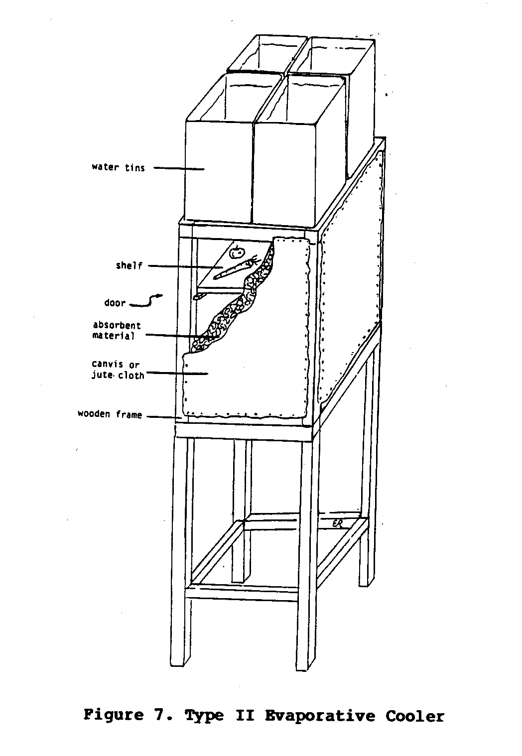
eastern Kenya. Four "debi tins" (these are rectangular containers, were originally used to store and transport biscuits) each with an eight-liter capacity, were used as water containers. The holes were first punched in the bottom of the containers, about 0.5 centimters apart, using a nail. Each hole was then filled with candle wax which was punctured with a small needle. The wax allowed for the experimentation necessary to achieve the proper size holes for the optimum rate of water flow.
The absorbent walls of this cooler were made by first attaching sheets of jute cloth on either side of a rectangular wooden frame made from five centimeters by five centimeters lengths of timber. Next, small mesh chicken wire was tacked over the jute cloth. From a notch cut through the top of the frame, small chunks (approximately 0.5 centimeters in diameter) of charcoal were poured into the frame and packed between the sheets of jute cloth. The chicken wire helped to keep the walls from bulging. The combination of jute cloth and charcoal allowed sufficient air flow to permit evaporation, while at the same time allowing the wall material to remain soaked with water.
On very hot, dry, and windy days, the four containers of water usually lasted the entire day. At the end of cooler, less windy days, the containers would often be found partially filled with water. The remaining water then be poured into a container and saved for the next day.
Fruits and vegetables were the primary foods kept in the cooler, but occasionally milk and meat were also stored for short periods of time. The reduction in temperature achieved by this cooler, along with the high level of humidity, were sufficient to allow the storage of most fruits and vegetables for five to ten days, and sometimes even longer. Vegetables that were stored in a shaded area would usually spoil in only two or three days. Milk or meat that was placed in the cooler in the morning would usually
be fresh in the evening when it was needed for the evening meal. When not stored in the cooler, milk and meat would usually be spoiled by mid-afternoon. Drinking water was also kept in the cooler. This provided a much more satisfying and refreshing drink than water kept in bottles placed either under trees or in the house.
On days when there was little or no wind, or when the humidity was high, the temperature in the cooler was not much less than the environment's. However, for most situations in eastern Kenya, this cooler prevented a substantial amount of food from spoiling and provided cool water for drinking.
The Type II cooler requires a some carpentry skill to build and tools such as a saw, hammer, block plane, and chisels. Additionally, the author used sawn timber, but it may be possible to use other materials and achieve a similar degree of efficiency. Even though charcoal and jute proved to be very effective materials for the cooler's walls, similar material could be substituted. Consideration needs to be given to the probable effectiveness of evaporative cooling for the specific environment under question before this cooler is built.
Type III Cooler
This third type of evaporative cooler, often referred to as the Janatha air cooler, was originally designed and built in India using baked clay building blocks called "Hourdis" block (Figure 8).
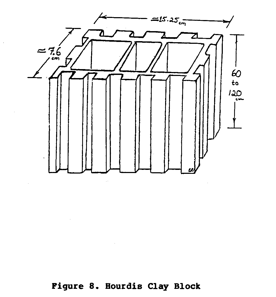
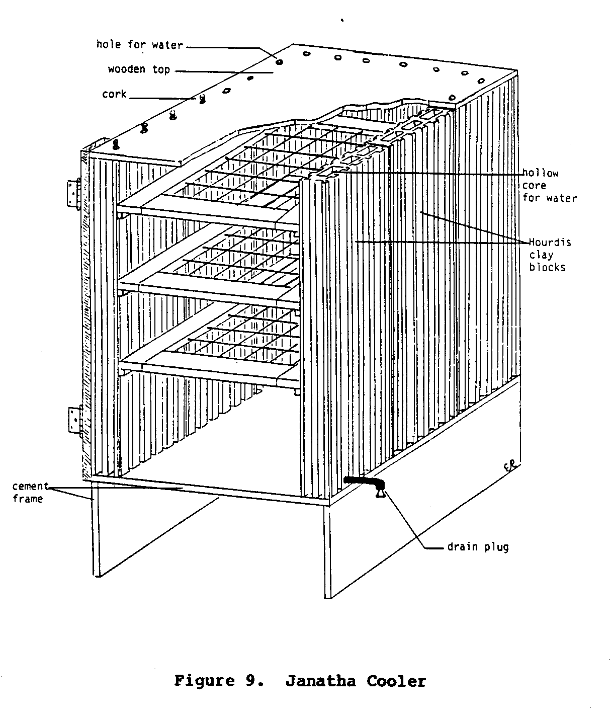
These blocks, are stacked together to form a rectangular three-walled enclosure. Slotted or grilled shelves are arranged in the cooler and a wooden top and door seal the structure. The cooler is usually built on a cement platform. The hollow core of each of the clay building blocks is kept filled with water. This water slowly seeps through the porous clay walls of the Hourdis block, eventually evaporating from the surface, thus cooling the entire structure. Small holes are often drilled in the sides of each of the blocks and fitted with short lengths of pipe that connect all of the hollow water-filled blocks together. From one of the blocks another short length of pipe is fitted to extend outside the cooler. This pipe is used to drain the cooler periodically to prevent a buildup of salt and mineral deposits in the pores of the baked clay. If the cooler is not drained, the flow of water through the pores of the clay will eventually stop. A diagram of a completed Type III cooler is illustrated in Figure 9.
Two graduate engineering students at the University of Texas designed an evaporative cooler similar to the Janatha air cooler. Instead of using baked clay, which is known to have a relatively low level of porosity (i.e., the ability of water to flow through the small pores present in a material), the students used blocks made from jute cloth saturated with a very watery cement mixture.
Before the cement dries and sets, the dip-molded blocks can be formed into desired shapes. This process of dip-molding allowed the experimenters to build large blocks that not only had a high level of porosity, but were also very strong and relatively light. Using this technology, the students built a cooler that used long tubular blocks (Figure 10).

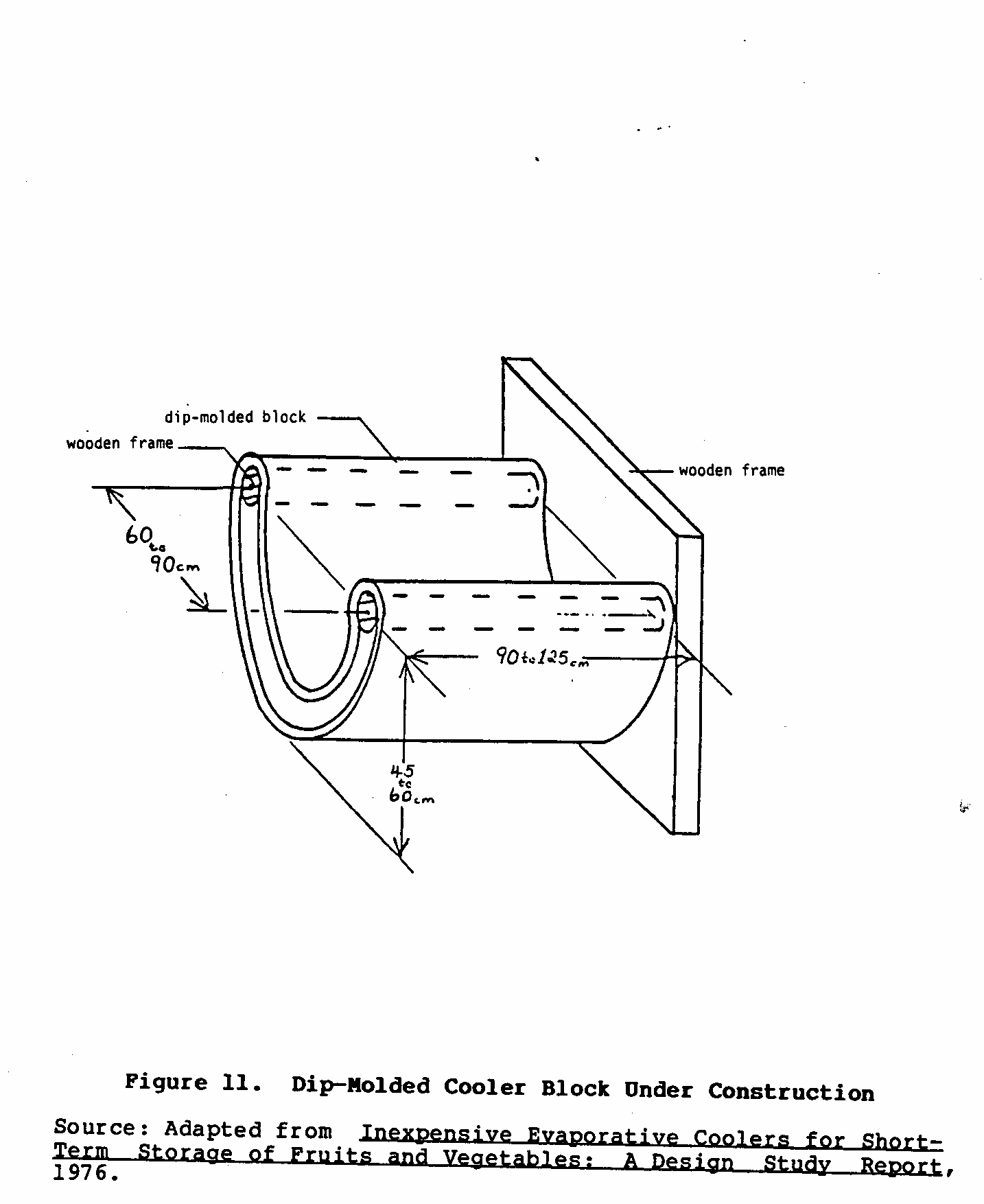
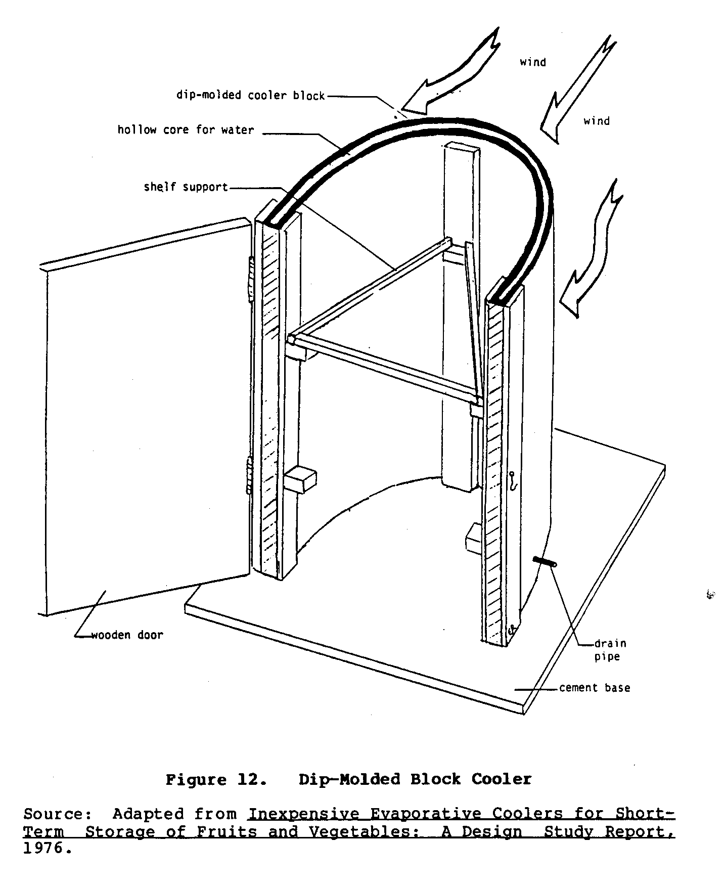
Other experiments with dip-molded blocks indicated that a single block could be shaped directly into the walls of the cooler (Figure 11). An experimental U-shaped cooler is shown in Figure 12.
Type IV Cooler
This final type of cooler uses electricity to power both a small fan and in some cases a small water pump. Essentially, this is a small version of the indoor curtain cooler described earlier. It can either be designed and built to be a permanent structure or it can be made as a portable unit. If a permanent cooler is desired, it can be built along the lines of the Type II cooler. Since a fan is used, the rate of air flow can be regulated to achieve an optimum rate. Moreover, the rate of evaporation and therefore cooling will be rapid since these systems are not at the mercy of intermittent winds. There are variations of this cooling system: (1) an electrified version of Type II cooler, and (2) a portable electric cooler.
The efficiency of the Type II cooler can be improved with the addition of a small fan and water pump. The fan can either be placed in the door or near the bottom of the cooler. The action of the fan draws air through the water-soaked walls of the cooler at a constant and even rate. This air, cooled through evaporation, cools the food and water stored in the cooler.
The containers of water used in the Type II cooler are replaced with small troughs positioned along the upper and lower edges of the cooler. The constant circulation of water ensures that the absorbent wall material is always soaked with water. The troughs along the bottom of the cooler should be built large enough to hold enough water for a full day's cooling.
* A detailed description of dip-molding can be found in the report by W. Hutchinson and R. Chuang, Inexpensive Evaporative Coolers for Short-Term Storage of Fruits and Vegetables: A Design Study Report (See Bibliography).
The second form of the Type IV cooler is an electric portable cooler. One such portable cooler was designed and built by two researchers at the University of California. Even though this portable evaporative cooler was intended to be used primarily by fruit growers in the Southwestern United States, it should also prove useful to individuals living throughout tropical and subtropical areas of the world.
Basically, this portable cooler is a simplified, single-walled version of the electrified Type II cooler. As shown in Figure 13,
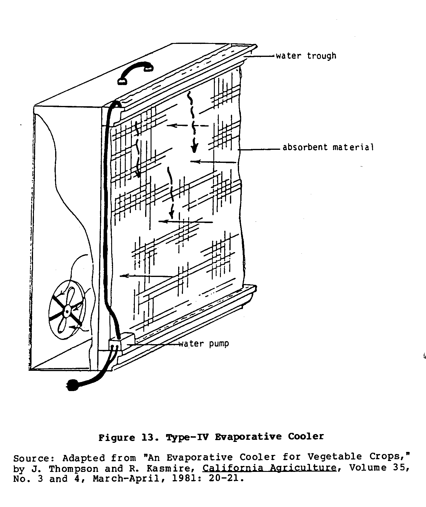
one wall is a sheet of absorbent material, while the opposite wall has a fan attached to it. Small troughs above and below the wall of absorbent material hold water. A drainage hose from the lower trough is connected through a small water pump to the trough on top of the cooler. This provides constant circulation of water through the system.
Boxes of fruits and vegetables are placed around the portable cooling unit. The fan forces cool moist air past the produce in the boxes. Figure 14 illustrates an example of this set-up.
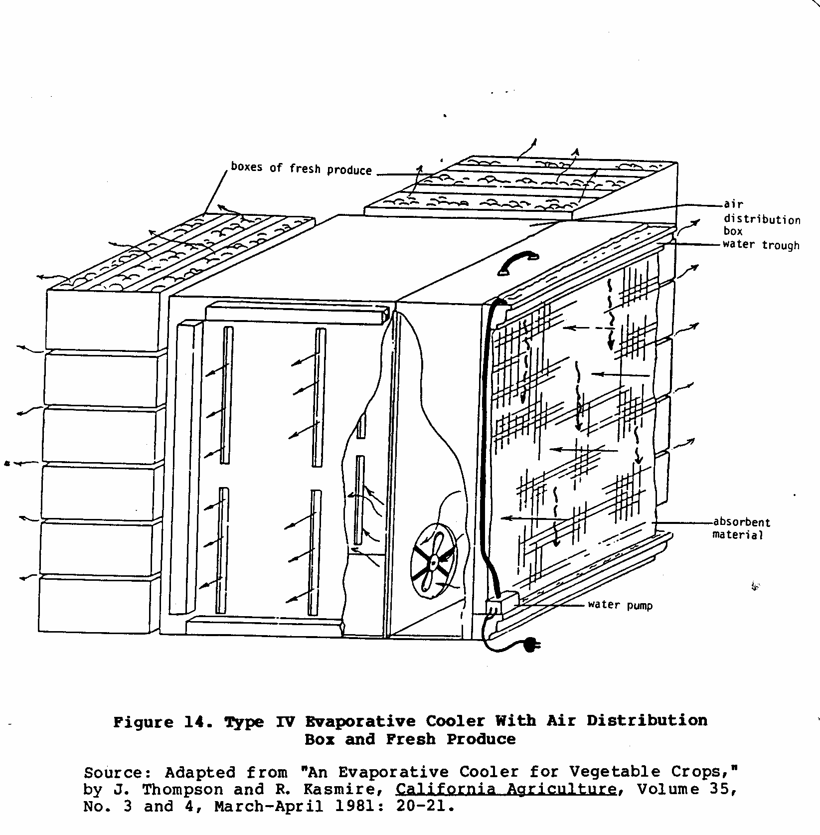
Slowly, the freshly picked produce will be cooled to temperatures that will promote optimum storage life.
This portable cooler has been designed to prevent produce from spoiling before it is sold or sent to market. Since this unit takes up very little space and consumes so little electricity, many fruit and vegetable vendors throughout the tropics may find this cooler a cost-effective method of protecting their valuable merchandise.
INDIRECT EVAPORATIVE COOLING
The high level of humidity that is produced by direct evaporative cooling may be undesirable for some applications. Indirect evaporative cooling attempts to solve this problem by using the cool moist air produced through evaporation to cool drier air. The resulting cool dry air is then used to cool the desired environment. This transfer of coolness is accomplished with the help of a heat exchanger.
All methods of indirect evaporative cooling require power to run both water pumps and fans. For this reason, indirect evaporative cooling will have limited application. It is primarily used to cool dwellings and rooms. In such situations these cooling systems are generally less expensive to buy or build and operate than conventional air conditioning systems. On the other hand, indirect evaporative cooling cannot be used in all environments, and the reduction in temperature that can be achieved with this system is not as great as the reduction that can be achieved with conventional mechanical cooling systems.
Basic Characteristics of a Beat Exchanger
Figure 15 is a simplified diagram of a heat exchanger. The heat
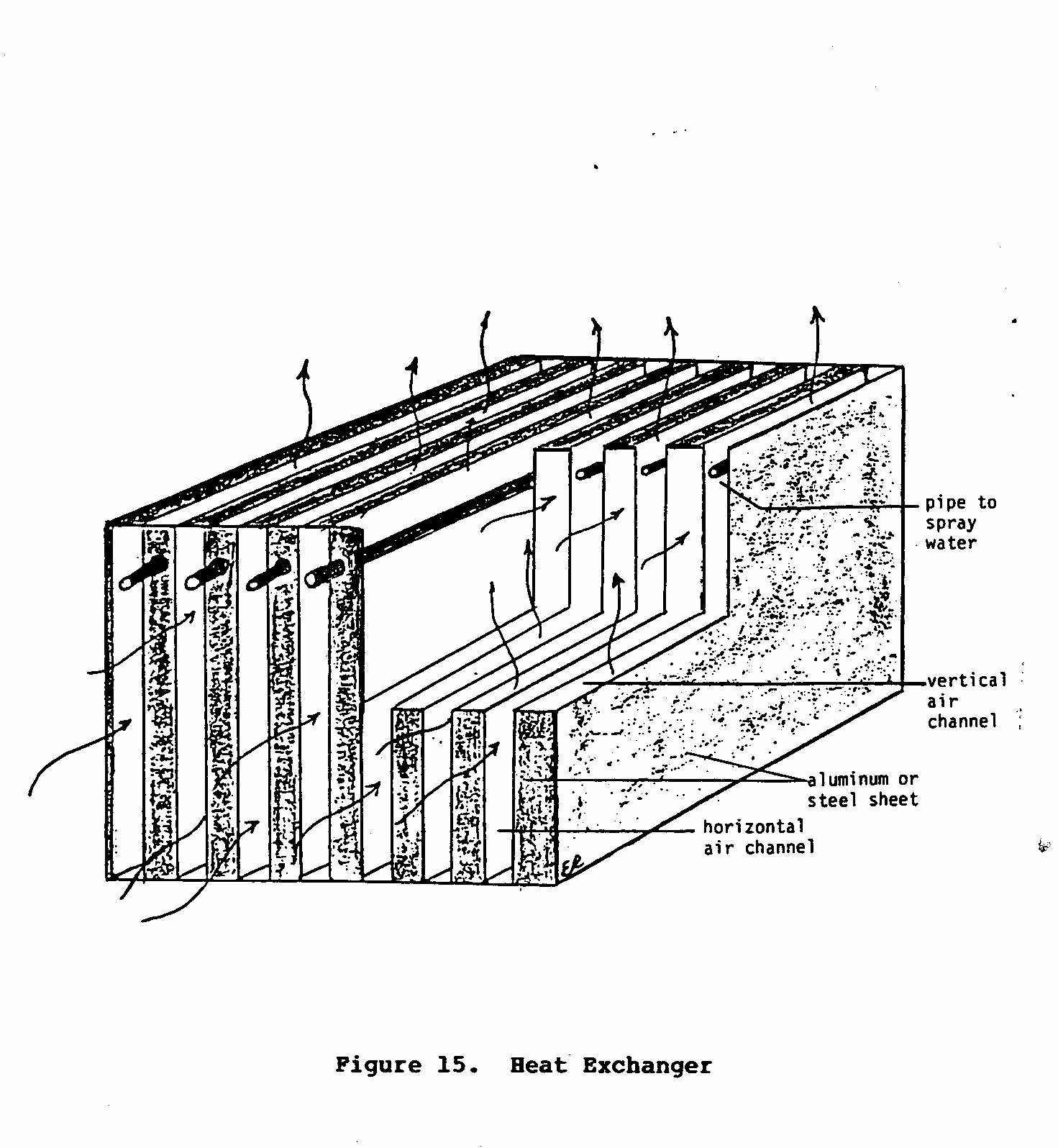
exchanger is composed of two sets of alternating channels through which air flows. The air that passes through the vertical channels comes in contact with water that is either being sprayed or dripped into the channel. If this air is warm and dry, evaporation and cooling will occur. This cool air then cools the channel walls, which in turn cools the air that is being forced through the horizontal set of channels. Finally, the cool moist air is directed outside the dwelling, while the cool dry air is blown into the room or building that needs to be cooled.
Factors That Effect Cooler's Effectiveness
As with direct evaporative cooling, several factors influence the effectiveness of this cooling system. Among the most important are the relative humidity and the temperature of the air being cooled. Low levels of relative humidity promote rapid evaporation and, therefore, a greater rate of cooling can be achieved. The rate of evaporation will also be increased if the air temperature is relatively high. Incoming air with a high temperature, however, will need more cooling than cooler air; therefore, high temperatures can be both an advantage and a disadvantage.
Two other factors that also affect the rate of cooling are the rate of air flow through the heat exchanger and the character of the water that is used in the evaporative cooling process. If the air is forced through the heat exchanger too quickly, little evaporation will take place, and therefore, little cooling will occur. Air turbulence within the channels may increase the rate of evaporation. The size of the water droplets will also influence the rate of cooling since it will have a significant affect on the rate of evaporation. If the water droplets are large, they will have a relatively small total surface area, compared to their volume, from which molecules of water can evaporate. Smaller droplets have a greater surface area, compared to their volume, and therefore, evaporation will occur more rapidly. This will in turn promote rapid cooling. Finally, the temperature of the water being sprayed or dripped into the channels will also affect the efficiency of the cooler. If the water is cold, the walls of the heat exchanger will cool down quickly. However, this may also slow down the rate of evaporation since cool droplets need to absorb more energy before evaporation occurs.
The design of the heat exchanger will also influence the rate at which cooling occurs. For example, small channel spaces will promote more rapid cooling than larger, more spacious channels. Moreover, if the heat exchanger is made from a material that conducts heat efficiently, such as metal, the transfer of coolness from the wet channels to the dry ones will occur more effectively.
Two Examples of Indirect Cooling Systems
There are two types of indirect evaporative cooling systems. The basic difference between these two systems is in the design of their heat exchangers. In one system, air is circulated through the heat exchanger in both horizontal and vertical directions (bidirectional). The air forced through the vertical set of channels will be [used to cool] the air flowing through the horizontal set of channels. The air in the horizontal channels remains dry and will be used to cool the room. In the second system, air flows through both sets of channels in the same direction, but like the first system, the cool dry air is released into the room while the cool moist air is directed outside.
Forcing air through the heat exchanger in two different directions (Figure 15) has the advantage of being able to use two different sources of air. For example, the air for evaporative cooling can be taken in from the room, while the air that is used to cool the room can be taken from the outside.
Figures 16 and 17 sketch the basic characteristics of one such

and the design of the heat exchanger and cooler can vary significantly depending upon the materials used and the skill of the builder. Figure 16 shows the two different air circulation
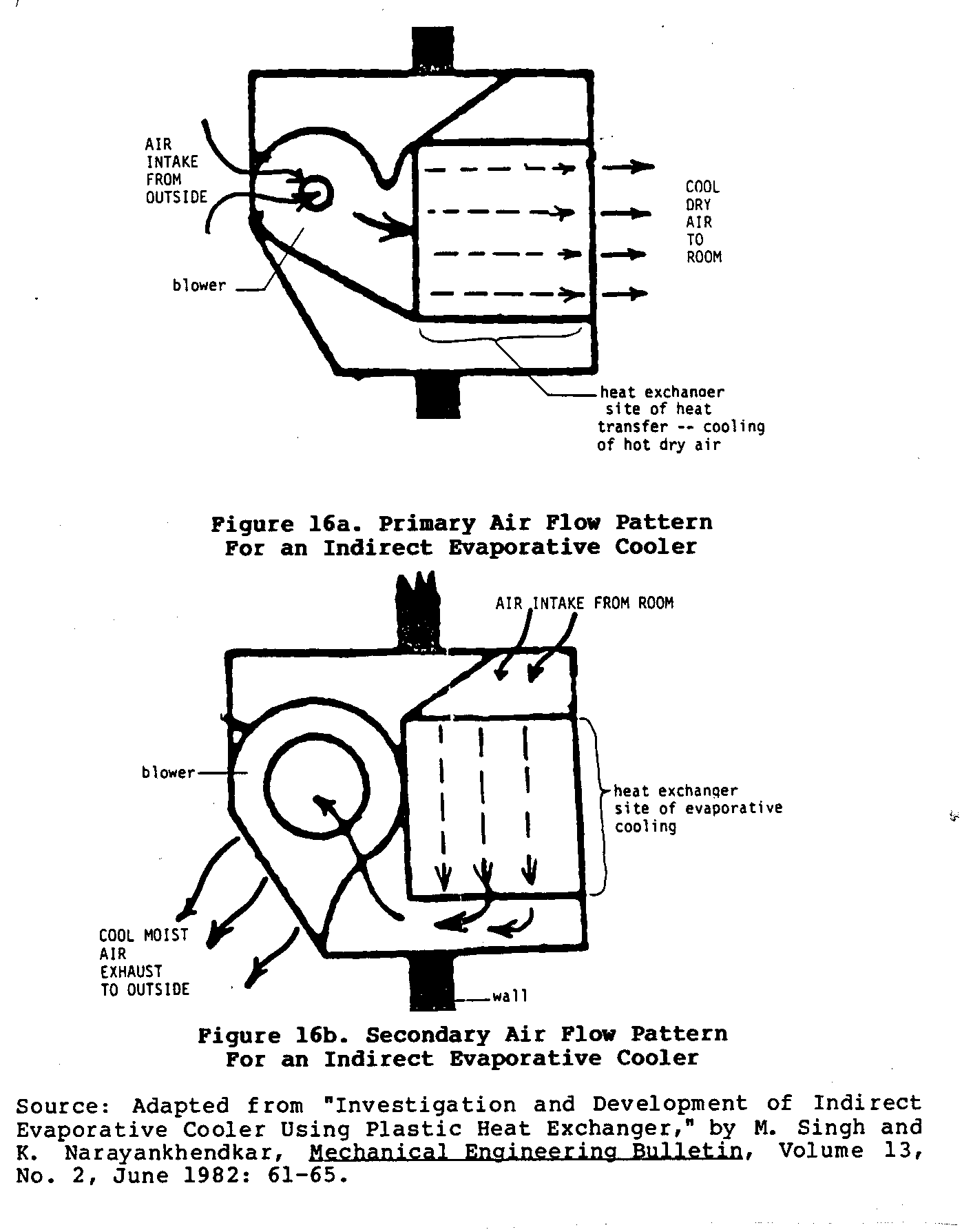
patterns mentioned earlier. Figure 17 shows four different views
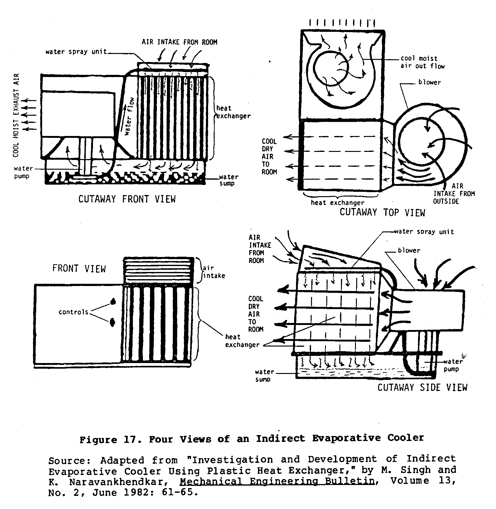
of a working model of bidirectional cooler. This type of cooler uses two blowers to achieve this bidirectional flow of air.
Most heat exchangers are made of metal, but a mass-produced plastic heat exchanger was used successfully in an indirect evaporative cooler in India. No matter what type of heat exchanger is used, it be important that it be designed and built to take advantage of the various principles that can positively influence evaporation and heat transfer.
The primary advantages of indirect evaporative cooling for increasing the comfort level of rooms are the relatively low purchase or building cost and the relatively low operation expense, as compared with conventional air conditioning systems. Before deciding upon indirect evaporative cooling, though, it is important that the necessary environmental conditions, discussed earlier, be present. The more favorable these conditions are, the more effective the cooler will operate. One such cooler, developed in Baghdad, Iraq, proved to be a practical alternative to conventional mechanical air conditioners. This cooler produced seven times the cooling was a conventional air conditioner, while consuming the same amount of electricity. This greater effectiveness was in part due to the 17[degrees] centigrade average difference between the wet- and dry-bulb temperatures common in Baghdad.
IV. COMPARING THE ALTERNATIVES
The principal alternatives to evaporative cooling systems are refrigeration and air conditioning. These technologies offer the user a much wider range of application. If electricity, (including that produced by photovoltaic cells), natural gas, or kerosene are available, commercial refrigeration and air conditioning systems can be used in any environment regardless of th temperature or relative humidity. This is definitely not the case with evaporative cooling. Moreover, commercial systems allow the user to control the amount of cooling desired. Again, this is not possible with most evaporative cooling systems. Another advantage of commercial systems is that they usually require less day to day attention than comparative evaporative cooling systems. However, where electricity or other commercial energy sources are either unavailable or very expensive, and the environmental conditions are favorable, evaporative cooling should be considered as a viable alternative to these more complex and costly commercial systems.
Although lowering the temperature of fruits and vegetables to retard spoilage is an important benefit of evaporative cooling, it is not the only one. Evaporation not only lowers the air temperature surrounding the produce, it also increases the moisture content of the air. This helps prevent the drying out of produce, and therefore extends its shelf life.
The primary advantage of evaporative cooling over cooling methods that involve commercial refrigeration is its low cost. For example, an evaporative cooling system developed in the United States to cool fresh produce was able to produce 14 energy units of cooling while using only one energy unit of electricity. Commercial refrigeration systems commonly produce only three energy units of cooling for each energy unit of electricity consumed. Low operating costs in addition to low purchase or construction costs substantially reduce the total cost of cooling by evaporation.
One final alternative deserves mention. It is possible to produce ice at night, even if the air temperature is above the freezing point, if certain specific conditions are met. This cooling and freezing is accomplished though the joint processes of radiation and evaporation and could be used to produce ice for cooling. To be effective, natural freezing requires appropriate levels of humidity, clear unobscured skies, and little or no wind. Arid environments usually offer such conditions.
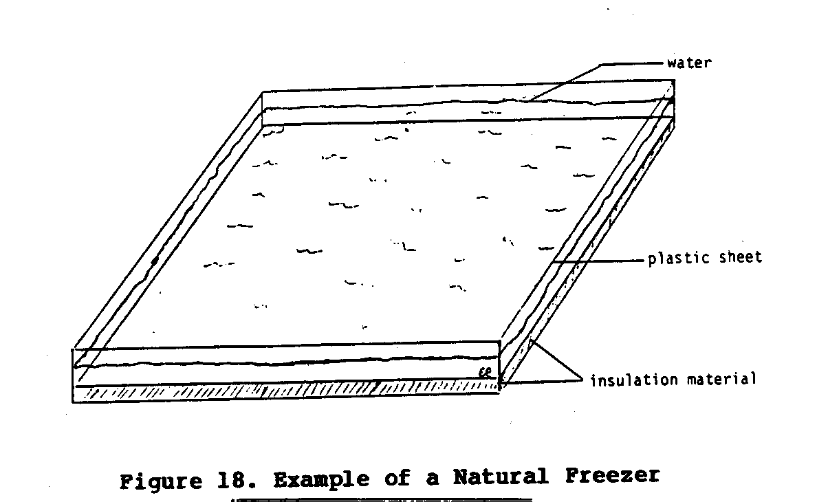
To produce ice this way all that is needed is a large flat container that has a clear view of the sky and is well insulated from the ground. Figure 19 shows one such set-up that regularly
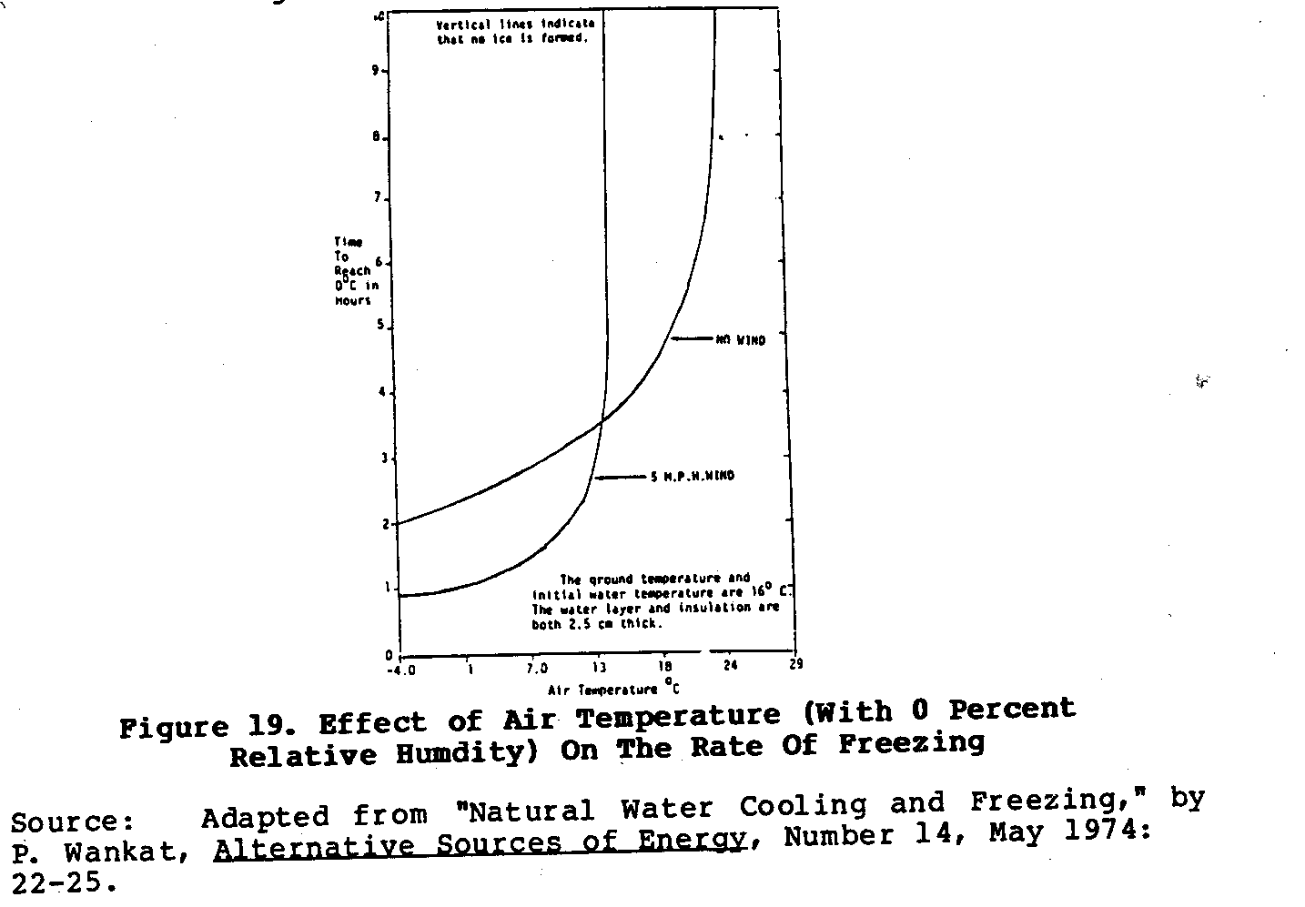
produced ice for a reseacher at Purdue University in the United States. This device was placed in a field away from all trees and buildings and filled with 2 - 3 centimeters of water. On nights with temperatures between 4 and 7[degrees]C and with relative humidities of 90 - 100 percent about 7.5M of ice would form on the surface of the water. If not collected and stored in an insulated cooler early in the morning, the ice would quickly melt soon after the sun rose. It is possible that enough ice to cool food for a 24- to 48- hour period could be produced using this process if a large enough natural freezer was used.
The chief disadvantage of this system is its dependence upon a narrow set of environmental conditions, and a corresponding lack of reliability. The graphs in Figures 20 and 21 show how
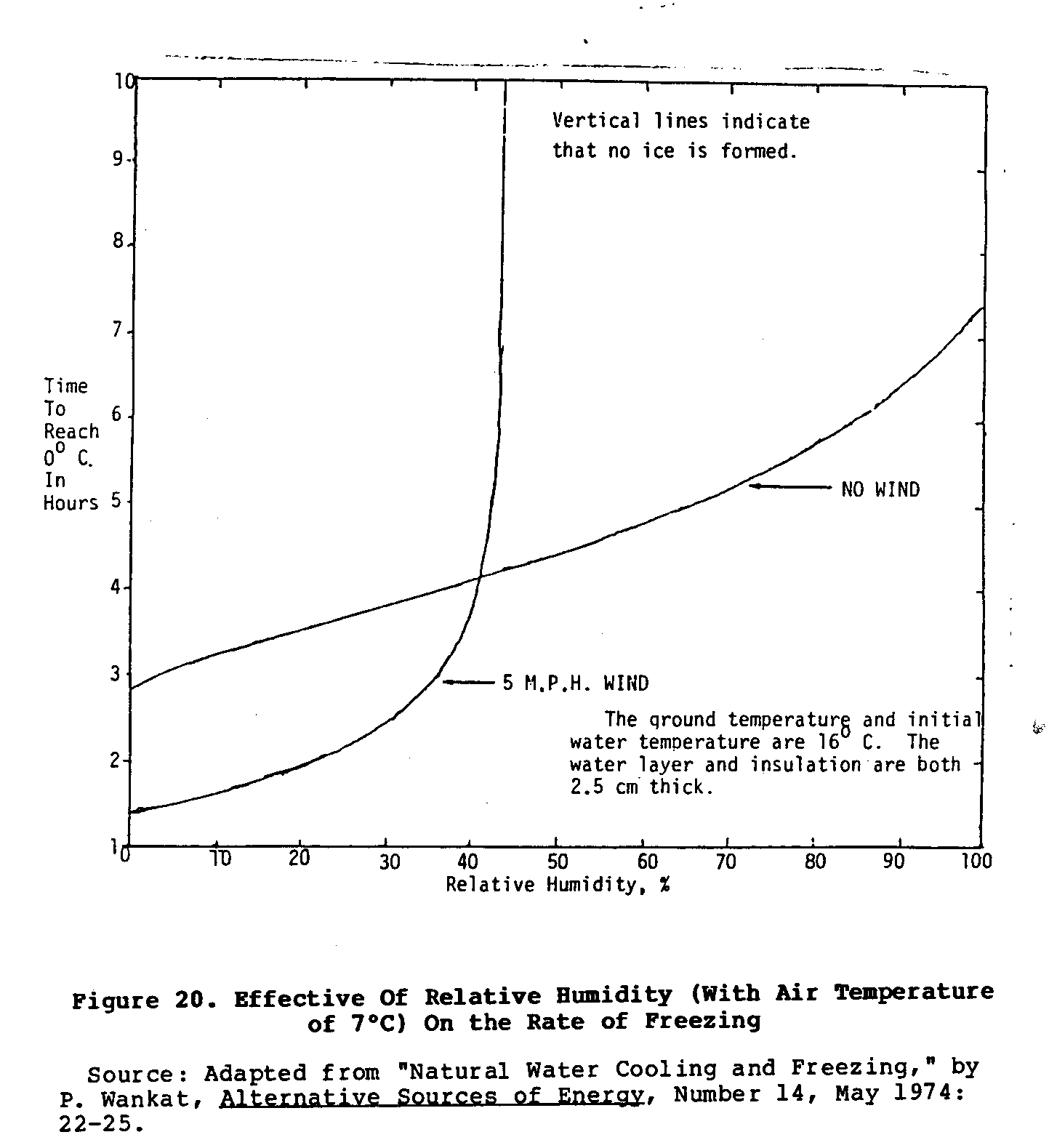
wind, air temperature, and relative humidity affect the rate of cooling of this natural freezer. Moreover, if the night is not perfectly clear, the rate of cooling is reduced. This system also requires the user to wake up before the sun rises to collect and store the ice that may have formed during the night. If little or no ice formed because of poor conditions, the user would be unable to cool stored food. However, if ice is needed only occasionally, this is an inexpensive method of making it.
V. CHOOSING THE TECHNOLOGY RIGHT FOR YOU
Making a decision on which type of cooling or refrigeration system to use is not an easy process. It is important to review carefully the cooling needs, weighing them against a range of other factors, before selecting any of the options discussed in this paper. If this is not done, frustration and disappointment may result. <see figure 18>
The following checklist may be useful in choosing a suitable technology. Since every situation is different, this checklist may not always apply, but it should be of some help.
- What are your cooling needs? Cooling different foods requires different temperatures. Cooling rooms or buildings is different from cooling food.
- What is the average relative humidity of the area where cool-is needed? If the relative humidity is consistently high, evaporative cooling will not be available option, and therefore another system needs to be considered. If the relative humidity is low, then evaporative cooling may be very effective.
- How windy is the area where the cooling is needed? If there is little wind, evaporative cooling may not be the way to go.
- Is there a good supply of water where the cooling system will be used? If water is readily available, evaporative cooling may be feasible.
- Are the materials and skills needed to build the cooler available?
- Is electricity available? Is it very costly? If electricity is available and affordable, then a powered evaporative cooler may be the best choice since it offers more freedom and is generally more effective than passive evaporative cooling systems.
- Are commercial mechanical cooling or refrigeration systems available? Are they costly? If commercial systems are available, and not too costly, then they may be a better choice of technology.
The design and construction of some of the evaporative coolers discussed in this paper may require the investment of a substantial amount of time and money. It may, therefore, be advantageous to turn the building of the evaporative cooler into a business. In India, for example, a local town builder has started a business building Janatha air coolers. Before this is done, however, it should be determined if there will be sufficient demand for such a cooler to warrent setting up a business.
If only a few individuals want to buy or build evaporative coolers it may be possible to build the coolers. By buying necessary parts in volume, and by contracting out for the actual construction, the group can reduce the cost per cooler. As with all cooperative efforts, it is important to keep very accurate records of all transactions.
REFERENCES
- "A Village Food Cooler", AP-Tech Newsletter, July 1980, Volume 4, No. 1, pp. 10-11.
- Akuffo, F.O. and K.D. Klorbortu, "Experiments on Food Storage in the Tropics Using Evaporative Cooling", VITA Document No. VIII-F-2; 013594.
- Dunkle, R.V., "A Method of Solar Air Conditioning:, Mechancal and Chemical Engineering-Transactions-of The Institution of Engineers, Australia, Volume 7, No. 3, September, 1984, pp. 1-2.
- Exell, R.H.B. "Solar Absorption Refrigerators in AIT", RERIC News, Bangkok, Thailand, Volume 7, No. 3, September 1984, pp. 1-2.
- Hutchinson, Bill and Roger Chuang Inexpensive Evaporative Coolers For Short Term Storage of Fruits and Vegetables: A Design Study Report. Mechanical Engineering Department, The University of Texas at Arlington. May 1976, VITA Document No. VIII-F-2-003317.
- Latif, Abbas A. and Nabeel A. Mahmood. "Indirect Evaporative Cooling", ASHRAE Journal, January 1968, pp. 61-67.
- Relative Humidity Tables, (prepared by) The Consumer Products of Sybron Corporation, Adren, North Carolina.
- Singh, Mastinder and K.G. Narayankhendkar. "Investigation and Development of Indirect Evaporative Cooling Using Plastic Heat Exchanger", Mechanical Engineering Bulletin, Volume 13, No. 2, June 1982, pp. 61-65.
- Thompson, James F. and Robert F. Kasmire. "An Evaporative Cooler for Vegetable Crops", California Agriculture, Volume 35, No. 3 and 4, March-April 1981, pp. 20-21.
- Thompson, James F. and Robert F. Kasmire. "An Evaporative Cooler for Vegetable Crops", California Agriculture, Volumne 35, No. 3 and 4, March-April 1981, pp. 20-21.
- Wankat, Philip. "Natural Water Cooling and Freezing:, Alternative Sources of Energy, No. 14, May 1974, pp. 22-25.