The plan presented here is a detailed description of a 1-kilowatt (1-kW) generator unit, which was prepared in 1971. The plan is scheduled to be revised and updated in the near future in order to incorporate additional data. At the time, this plan was prepared, the generator had not been built on the scale shown here. Therefore, until such time as testing results can be integrated into the plan, VITA offers this material as an idea paper.
By way of background, the designer of the 1-kW river generator made the following assumption in his calculations:
80% efficiency for each of the three "V"-belt speed-up stages so that enough power is available to operate the unit at 4.7 ft/sec water velocity. It will certainly operate at 6.0 ft/sec.
Mathew G. Boissevain is a design engineer at a major U.S. corporation. During his many years as a VITA Volunteer, he has developed several types of water wheels for powering water pumps and has worked for almost 20 years designing machines used in automated processes--for example, artificial kidney equipment, circular weaving loom, various mail-sorting devices, food-processing machines.
Please send testing results, comments, suggestions, and requests for further information to:
VITA 1600 Wilson Boulevard, Suite 500 Arlington, Virginia 22209 USA Tel: 703/276-1800 * Fax: 703/243-1865 Internet: pr-info@vita.org 0-86619-079-1
VITA Technical Bulletins offer do-it-yourself technology information on a wide variety of subjects.
The Bulletins are idea generators intended not so much to provide a definitive answer as to guide the user's thinking and planning. Premises are sound and testing results are provided, if available.
Evaluations and comments based on each user's experience are requested. Results are incorporated into subsequent editions, thus providing additional guidelines for adaptation and use in a greater variety of conditions.
WHAT IT IS
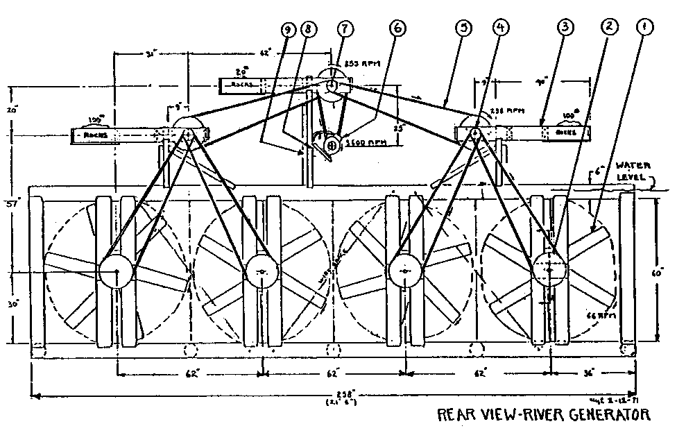
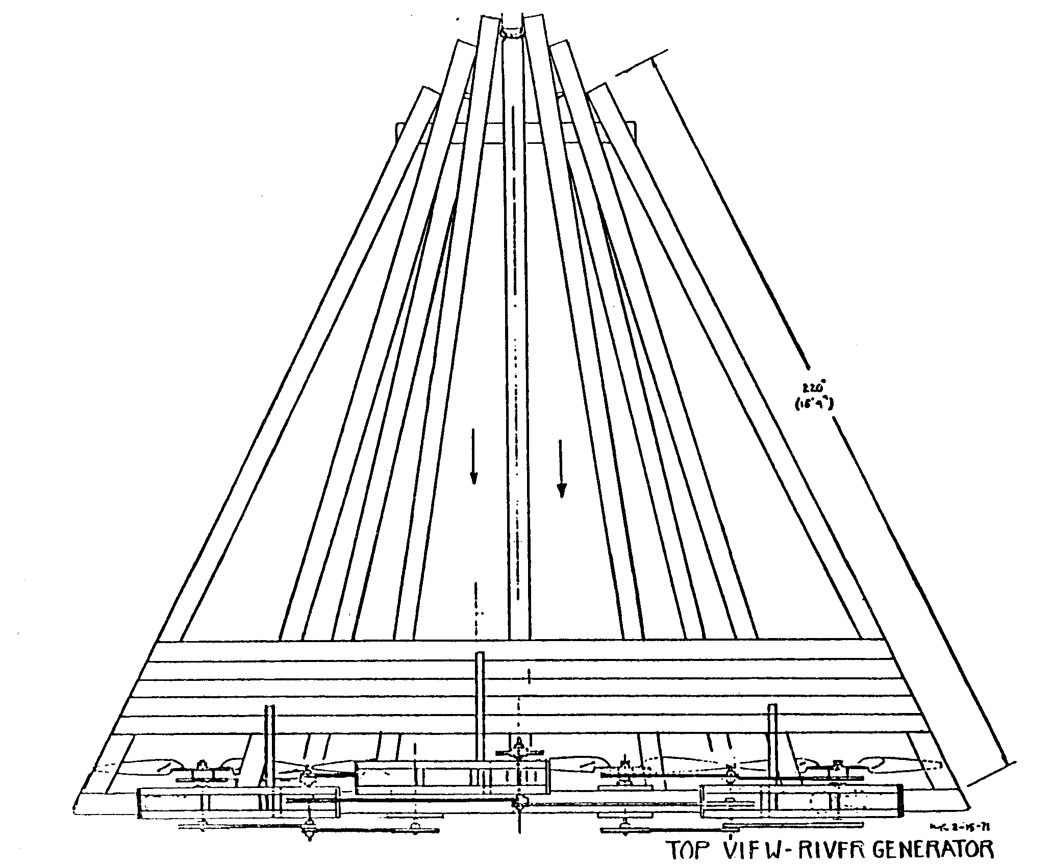
The river generator uses the flow of river water to produce 1-kW of electrical power. It has four 5-ft diameter propellers attached to a log float. The float is anchored to the river bottom.
From actual trials with 40" propellers, it is calculated that water flowing at 4.7 to 6.0 ft/sec will turn the 5-ft propellers with enough power to generate 1000 watts of electricity.
The propellers are connected to the generator by a series of "V"-belt pulley drives that speed up the slow 66-revolutions per minute (rpm) of the propellers to the fast 3600-rpm of the generator.
A variable speed pulley at the generator and a built-in volt meter will enable the user to adjust the generator rpm and voltage for varying river flow and generator load conditions. Most of the pulleys, shafts, and "V"-belts are identical. This simplifies building and reduces spare parts needed.
Due to slow speeds (except at the last stage) the unit should last a long time, if built as instructed. It does not need elaborate dams, river falls, or pipes, as do Most hydroelectric plants. You can build as many of these generators as needed, spaced about 100 feet apart downstream. By comparison, a paddle wheel, under identical conditions, would need paddles at least as large as the entire back frame of the river generator (see drawing, rear view) to provide the same amount of power. Also, it would only turn at about 5-7 rpm and would need more speed-up stages of "V"-belts.
The 1-kW river generator will produce about 720-kW hours per month, which should be enough energy to run a simple household.
Some effort must be made to conserve energy, and to spread energy use as evenly through the day as possible.
WHAT YOU NEED TO BUILD ONE
This design requires access to a river that runs with a speed of from 4.7 to 6.0-ft/sec year round with a depth of at least 6-ft over a 21-ft width. This principle will also work on a smaller scale with a corresponding reduction in power output. If you have access to a waterfall or higher water speeds, you could make a 1-kW or bigger unit with smaller (but stronger) propellers, turning at higher speeds, and with fewer pulleys and belts. These higher speeds can also be obtained by building dams, etc.
Purchased parts (see parts list) total US$612.81, based on 1971 list prices in the United States. To this, you must add tax and shipping and the cost of all lumber and logs used. To reduce cost, you may be able to find your own parts (airplane propellers, large fans, washing machine pulleys, etc.). Because prices may have changed drastically since 1971, be sure it is economically feasible before you begin construction.
Tools
* Wood saw
* Hammer and/or hatchet
* 1" wood drill
* 1/2" wood drill * 3/16" metal drill (for nail holes in item 21) * Allen wrenches (for 1/4" set screws in pulleys)
* Metal file * Pliers to cut and twist 1/8" wire
* Wrench for 1/4" bolts in propellers * .669" diameter drill for increasing hole in cast iron pulley (item 13) from .625" diameter to .669/.673" diameter.
Lumber
* 14 straight logs, 5"-8" diameter X 21' (Bamboo may also be used instead of logs. Use wire around joints to make strong, durable structure.)
* Planks, 2" X 4"; as shown on page 9.
WHERE TO BUILD
Find a place in your river, close to home, that has a water speed of 4.7 to 6.0-ft/sec. This must be measured exactly. (At 3-ft/sec water speed, you will get only about one-fourth of the power, or 250 watts.) To measure the speed, measure off 50-feet along the river bank and mark with sticks. Then, count the exact time required for the water to carry a log or branch between the sticks. The time must be 8.3 to 10.6 seconds. The place to build your river generator is upstream from the location chosen, so it can be launched like a large boat and floated into place. After the frame has been built, attach the rope (item 20) to the pointed end and anchor the float in place, using a boat anchor, a large rock, or a 2-inch steel pipe driven into the river bottom.
HOW TO BUILD
Float. Before spending money on parts, it may be wise to build the log frame and test it out to make sure it holds together under all river-flood conditions. The author has successfully built smaller frames than the one shown. Unforeseen problems may arise with a larger one.
Build the frame as shown in the following drawings. Be sure to reinforce all the joints with metal plates (item 21). (Tin cans could possibly be used here. Remove ends, flatten, then dip in paint to prevent rusting.) The wire (item 22) is used to keep branches, etc., out of the propellers. Also, use wire braces at the back section (see rear view), and on all joints when building the frame with bamboo instead of logs.
Drive System. Next, make all the wooden parts shown on the "side view" drawing. Items 18 and 19 should be made of hardwood. Soak it in water after drilling the hole. Then open up the hole as needed until the 1-inch shaft turns smoothly. Do the same for item 3 (pivoting frames--to provide V-belt tension), but soak it in oil around the hole where the shaft goes by filling oil holes after shaft is assembled. Enlarge if necessary to provide smooth running shaft.
Attach item 9 to the vertical members on the float, with the shaft in place. Make sure the shaft is square with the frame as shown in the drawing. It is important to end up with the dimensions as shown in the "rear view" drawing, because the "V"-belts are not adjustable in length.
Shafts. Attach the pulleys to all the shafts, as shown. File or drill 1/8-inch into the shaft under all the set screws. This prevents the pulleys from turning on the shaft. The propellers attach with a split bushing and will grip the shaft tightly when the bushing is bolted tightly against the propeller hub.
Belts. Install all propeller belts and weight down each item 3 on both sides of center with rocks, as shown. This will provide a constant, even tension on the belts and reduce belt wear. Allow the belts to set in the exact position of item 12 before bracing it as shown on the "rear view" drawing.
Repeat above with the tall item 12 at the center of the float. After the unit is back in the water and operating under load, add rocks as needed to prevent belt slippage. Don't make the belts too tight as this increases wear.
Adjust the variable speed pulley on the generator to get the 120-volts needed. Be careful to ground the generator housing and ground wire in the water, and to keep people away who don't know the dangers of 120-volts of electricity and wet feet in water, etc.
Insulate all exposed wire. Follow wiring instructions that come with the generator, and run the cable down the anchor rope, then along the river bottom (weight with rocks) to the shore. Propeller Blade Tip Angle Adjustment. At 4.7-ft/sec water velocity, the propeller must turn at 60 to 70-rpm. Twist the propeller tip until the blade is angled as shown below. All blades must have a 9 [degrees] angle.
SUGGESTED SUPPLIERS
Grainger W. W. Grainer, Inc., 519 Potrero, San Francisco, California U.S.A. [Phone: (415) 861-48411]
Browning Browning Mfg. Division, Emerson Electric Co., Maysville, Kentucky 41056 U.S.A.
Ryerson Ryerson Steel, Box 8427, Emeryville, California 94608 U.S.A. (also, U.S. Steel)
Durkee Atwood Durkee Atwood Co., Minneapolis, Minnesota 55413 U.S.A. [Phone: (612) 332-0441]
Sears, Roebuck & Co. Los Angeles, California 90054 U.S.A. (NOTE: Drill item 13 from .625" diameter to .669" diameter.)
PARTS LIST
Item Quantity Cost Total Number Needed Description Stock Number Each Cost Where to Buy
1 4 60" exhaust fan, 1" bore 3 CO 32 41.35 165.40 Grainger 2 14 14" pulley, 1" bore 3 X 944 3.82 53.48 Grainger 4 14 4" pulley, 1" bore AS-40 2.53 35.42 Browning 5 14 "A" section "V"-belt A 158 6.43 90.02 Durkee Atwood 6 1 Alternator, 1.2-kW, 115-Volt F32 KF 32054 N 119.00 119.00 Sears 7 8 1" X 18" long shaft Type 303 SS 61.00 61.00 Ryerson 8 2 3" door hinge 1.20 1.20 (local) 9 250 ft Underground cable, 12 gauge, 5/8" bore 1 W 676 26.75 26.75 Grainger 13 2 Variable pitch pulley 3 X 276 2.77 5.54 Grainger 15 2 "A" section "V"-belt A-75 5.00 10.00 Durkee Atwood 17 36 (14#) 4" X 8" X .125" thick 6061-T6 alum 8.00 Ryerson 18 12 1" flat washer plated steel 1.00 (local) 20 50 ft 1" diameter rope 25.00 (local) 21 20 lb 4" long nails, plated wire 6.00 (local) 22 300 ft 1/8" soft galvanized steel 5.00 Ryerson
Total cost of all purchased parts except wood $612.81 Add tax and shipping
<FIGURE 2>

<FIGURE 3>
<FIGURE 4>