This bulletin contains step-by-step procedures for parts manufacture and assembly of a hand-operated machine for making chain link fencing. The machine here is designed to produce fencing up to 244 cm (96") but can be used to produce fencing of any height. The size of the openings in the fencing is controlled by the size of the "bending-head." The machine described here requires 12 or #14 wire, but the machine could be modified to take larger wire.
The chain link fence making machine was designed by VITA in response to requests from South America and Africa. In Botswana, the machine has become the basis for a small fence manufacturing business which serves as a source of employment and produces fencing which is far more affordable locally than is the imported fencing which was the only material previously available.
Please send testing results, comments, suggestions and requests for further information to:
VITA 1600 Wilson Boulevard, Suite 500 Arlington, Virginia 22209 USA Tel: 703/276-1800 . Fax: 703/243-1865 Internet: pr-info@vita.org
ISBN 0-86619-105-4
VOLUNTEERS IN TECHNICAL ASSISTANCE
VITA TECHNICAL BULLETINS
This Technical Bulletin is one of a series of publications that offer do-it-yourself technology information on a wide variety of subjects.
Technical Bulletins are idea generators, intended not so much to provide a definitive answer as to guide the user's thinking and planning. Premises are sound and testing results are provided, if available.
Users of the information are asked to send us their evaluations and comments based on their experiences. Results are incorporated into subsequent editions, thus providing additional guidelines for adaptation and use in a greater variety of conditions.
FABRICATION
Clamp two halves of crankshaft-bearing block (1A) in vise, drill two 0.6cm (1/4") diameter holes vertically through both halves and drill 2.5cm (1") diameter hole horizontally.<see figure 1>
Similarly, clamp and drill two 0.6cm (1/4") diameter and one 5.7cm (2 1/4") diameter holes in bending-head block (1B); also drill 0.6cm (1/4") diameter vertical hole with 1.3cm (1/2") diameter x 0.6cm (1/4") deep counterbore in top half.
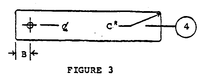
Drill 0.6cm (1/4") diameter hole in bending-head arm (4) and round off corners. <see figure 3>
DIMENSION CENTIMETERS INCHES
A 5 2 B 1 3/8 C 0.5 3/16 D 21 8 3/8 E 3.2 1 1/4 F 0.5 3/16 G 16 6 1/4 H 3.7 1 1/2 I 11 4 1/4 J 5 1 7/8 K 14 5 5/8 L 13 5 1/4 M 38 1
ASSEMBLY
1. Assemble Tension-Assembly as Shown.
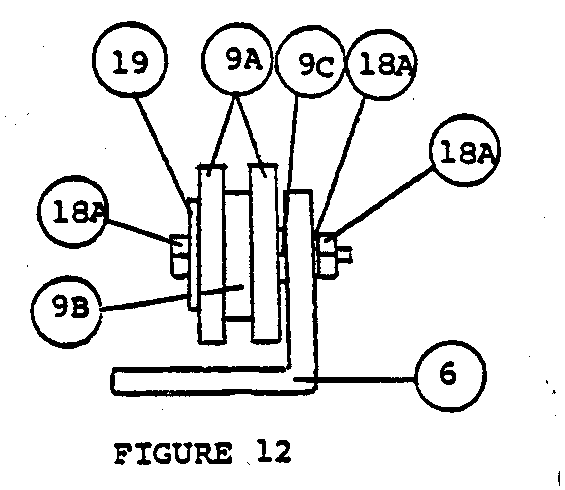
Assemble tension-assembly sheaves in one way. <fig. 11 & 12>
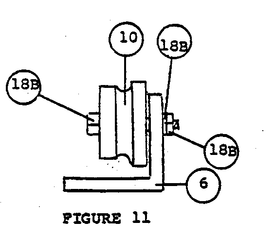
Bearing pipe ODs in Figure 12 may have to be filed slightly so that sheaves are snugly free-turning.
2. Assemble bending-head assembly
Crankshaft OD may have to be filed slightly so that handle (1) is snugly free-turning; bending-head arm (4) width may have to be filed slightly so that it is snugly free-turning inside pipe.
3. Fasten machine bed (2) to suitable sturdy legs approximately 90cm (36") above floor.
4. Mount all machine components to bed (2) as shown in top and side views.
Cross-section assembly view of bending-head mounting; force nut (14) into counterbored bending-head block (1B), place bending-head brace (8) on top of block and mount to bed (2) with bolts (13), flat washers, lockwashers and nuts; thread bolt (14) through nut until end of bolt is flush with bending-head pipe ID; tighten second nut to prevent loosening.
5. Bend crankshaft (5), cut slot in end indicated, drill 0.6cm (1/4") diameter hole through slotted end and drill four 0.3cm (1/8") diameter holes.
6. Cut 0.5cm (3/16") wide spiral slot in bending-head pipe (7); to mark spiral, cut strip of heavy paper 8cm (3 1/8") wide and wrap around pipe. Drill 0.6cm (1/4") diameter hole in top of pipe.
Smoothing the Spiral Groove
It is necessary to smooth the spiral groove with a small file so that the wire will move freely through the bending-head.
Strengthening the Bending-Head
To make the bending-head stronger, start with a piece of pipe 2" (5cm) longer than required. Cut the spiral groove as described in the instructions leaving the 2" uncut portion at the end near the crank. Made in this way the pipe will hold its original shape much better and the uncut part will not interfere with the operation of the machine.
Alternate Method of Crank Construction
The crank can be made from 1/2" diameter pipe and fittings, if available.
Alternate Method of Constructing Tension-Assembly
A very simple and suitable tension-assembly can be made with wooden pegs mounted in a board as shown below. The wire is passed around as many of the pegs as necessary to provide the proper tension. As wear begins to show on the pegs they can be driven into the board until the area of wear disappears. After some time it will be necessary to replace the pegs.
The positioning of the wooden peg tension-assembly will depend on the general construction of the machine. If it is built with wooden legs, the pegs can be placed in the leg nearest the bending-head to form the tensioning device. Otherwise, the tension-assembly must be constructed as a separate piece and attached to the machine bed in the appropriate position.
6 Drill three 0.6cm (1/4") diameter holes in bending-head brace (8). <see figure 6>
7 Form hooks (11). <see figure 7>
8 Drill three 1.3cm (1/2") diameter and three 0.6cm (1/4") diameter holes in tension-assembly base (6). <see figure 8>
9 There are two methods of fabricating the tension-assembly sheaves (9A & 9B, or 10) and their axles (26A or 26B):
a. Preferred method, if use of lathe is possible, Figure 9 cross-section view: fabricate sheaves (10) as shown.
b. Alternate method, if use of lathe is not possible, Figure 10 cross-section view: assemble sheaves (2-9A & 1-9B) each) with bearings (9C) as shown; file bearing (9C) lengths so that assembled sheaves will revolve sungly; 9A and 9B may each be built up of series of thin washers, if necessary.
SOME ADDITIONAL NOTES ON THE CHAIN-LINK FENCE-MAKING MACHINE <see figures>
Making the spiral groove in the pipe.
The width of the paper used for marking the spiral groove is: 2 5/8" (6.7cm) wide for 1 1/2" (3.8cm) pipe 3 1/8" (8cm) wide for 2" (5cm) pipe
The paper is wrapped spirally around the pipe with just enough space between the edges of the paper to mark with a pencil.
Using a hacksaw, cut along this line, rotating the pipe so that the blade just goes through the metal. Too deep a cut will cause the hacksaw blade to bind.
A second cut is made near the first so that the resulting groove is 3/16" (0.5cm) wide.
OPERATION
1. Feed #12 or #14 wire from wire feed roll over nearest tension-sheave; under middle tension-sheave and over last tension-sheave into spiral slot in bending-head pipe.
2. Figure 17: Clockwise rotation of crankshaft handle will produce properly formed wire at output end of bending head; continue rotating crankshaft handle until formed wire is of sufficient length for desired fence height.
3. Figure 17: Cut wire and rotate handle so that a second strand is formed which will interlock with first strand.
4. Figure 17: Continue the above procedure until fence length reaches end of machine-bed; hook hooks (11) to last formed strand to support fence and continue as above. As each strand is completed, move hooks to that strand.
5. 5cm (2") ID bending-head pipe used with 5cm (2") wide bending-head arm will make fencing with 10cm (4") mesh, while 3.8cm (1 1/2") ID pipe and 3.8cm (1 1/2") wide arm will make 7.6cm (3") mesh.
6. Lubricate both bending-head assembly and tension-assembly occasionally. Soap makes the best lubricant for the bending-head because it does not leave the fence dirty as does oil or grease. The soap can be applied as a thick soap and water solution to the bending-head itself or by allowing the wire to pass over a dry bar of soap just before it enters the bending-head--after passing through the tension assembly.
The parts are assembled by bolting the blocks "C" and "D" to a sturdy, narrow table or work bench, as shown above. If such a work bench is not available, it may be constructed for this purpose. The top of the bench should be made of a plank 1 foot wide, 10 feet long, and 1-1/2 inches in thickness. As the wire feeds off the supply roll, it goes first through the pulley assembly. It goes over the first pulley, under the second, and over the third. The end of the wire is then inserted in the slot in the pipe "A". When the crank is turned (clockwise) the wire winds around the steel plate or "bending arm", follows the spiral slot, and is forced out the other end in the form of a flat spiral. When the spiral strand reaches the desired length, it is cut off with wire-cutting pliers. The first strand is held in place while the next strand winds itself around the first. A narrow board (1 inch x 4 inches x 103 inches) is fastened to one side of the work bench, as shown above. Wire hooks are arranged along the edge of this board, and are used to hold the finished section of wire in place, while each succeeding strand is being made. This arrangement holds the fencing up off the table, so that the spiral has room to turn. As each strand is cut off, the two ends are twisted together with the ends of the preceding strand. Finished fencing accumulates on a roll on the floor beside the work bench. For continuous production, a rack may be prepared, with an axle-and-crank arrangement, on which the finished wire may be rolled up as it accumulates. Also, for continuous production, it is best always to leave a short section of fencing in line on the machine, since the first few strands are always somewhat difficult to hold in line. To separate two sections of fencing, it is not necessary to cut the wire; simply loosen the two ends of one of the strands and turn the spiral backwards out of the fencing.
An abstract of the fence-making machine as it appeared in "World Neighbors in Action." <see figure>
A. The size of this pipe determines the size of the openings in the mesh. A 2-inch pipe will make fencing with 4-inch openings. To mark the spiral, cut a strip of heavy paper 3-1/8 inches wide and wrap it around the pipe. To cut the spiral slot, a hacksaw is used. The slot should be 3/16 inches wide. A 1/4-inch hole is drilled in the top of the pipe, for holding it in place.
B. This "blade" may be made from steel or strap iron. It must be tough enough so that it will not tend to twist out of shape with use. The edges should be filed off so that it fits snugly but turns freely inside the pipe.
C. Two blocks are clamped together and a 1-inch hole bored between them horizontally, as shown. Two 1/4-inch holes are also drilled vertically, for fastening the blocks to the work bench.
D. In the same way, the two blocks are clamped together. A hole 2-1/4 inches in diameter is bored horizontally, and three 1/4-inch holes are drilled vertically, as shown. The top center hold also requires a 1/2-inch counterbore, (1/4-inch deep) in the top block, to admit a locknut. A 6-inch strap iron is also drilled with three
1/4-inch holes to match the holes in the blocks. (See Figure 3 on page 5).
E. The crank may be made from a 1-inch rod, 31 inches in length. A 3/16-inch slot is cut in the end, so that it will fit over the "blade", or bending arm. Holes are drilled as indicated, to hold the crank in place. A 5-inch length of pipe is fitted over the handle, so the crank will turn easily in the hand.
F. The size of the pulley sheaves is not especially important. A 1-1/2 or 2-inch diameter is a good size to use.
[C] VITA, Inc. 1978
VITA VOLUNTEERS IN TECHNICAL ASSISTANCE
ABOUT VITA
Volunteers in Technical Assistance (VITA) is a private, nonprofit, international development organization. Started in 1959 by a group of concerned scientists and engineers, VITA maintains an extensive documentation center and worldwide roster of volunteer technical experts. VITA makes available to individuals and groups in developing countries a variety of information and technical resources aimed at fostering self-sufficiency--needs assessment and program development support; by-mail and on-site consulting services; information systems training. It also publishes a quarterly newsletter and a variety of technical manuals and bulletins.
VITA 1600 Wilson Boulevard, Suite 500 Arlington, Virginia 22209 USA Tel: 703/276-1800 . Fax: 703/243-1865 Internet: pr-info@vita.org